Model 8715 DP-CALCTM Micromanometer and Model 8380 ... - TSI
Model 8715 DP-CALCTM Micromanometer and Model 8380 ... - TSI
Model 8715 DP-CALCTM Micromanometer and Model 8380 ... - TSI
- No tags were found...

Create successful ePaper yourself
Turn your PDF publications into a flip-book with our unique Google optimized e-Paper software.
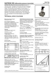
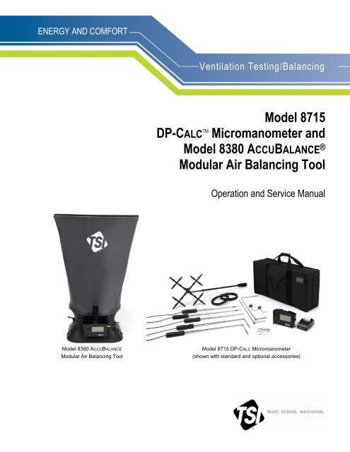
ENERGY AND COMFORTVentilation Testing/Balancing<strong>Model</strong> <strong>8715</strong><strong>DP</strong>-CALC TM <strong>Micromanometer</strong> <strong>and</strong><strong>Model</strong> <strong>8380</strong> ACCUBALANCE ®Modular Air Balancing ToolOperation <strong>and</strong> Service Manual<strong>Model</strong> <strong>8380</strong> ACCUBALANCEModular Air Balancing Tool<strong>Model</strong> <strong>8715</strong> <strong>DP</strong>-CALC <strong>Micromanometer</strong>(shown with st<strong>and</strong>ard <strong>and</strong> optional accessories)
CONTENTSAbout This Manual ...................................................................................................................... vFormatting <strong>and</strong> Typography .................................................................................................... vTechnical Assistance—Help! .................................................................................................. vChapter 1. Introduction .............................................................................................................. 1Instrument Description ............................................................................................................ 1<strong>Micromanometer</strong> ............................................................................................................... 2<strong>Micromanometer</strong> ..................................................................................................................... 3St<strong>and</strong>ard Tools ........................................................................................................................ 4Pitot Tube .......................................................................................................................... 4Static Pressure Probe ....................................................................................................... 4Balometer ® Capture Hoods ............................................................................................... 4Optional Tools ......................................................................................................................... 4Velocity Matrix ................................................................................................................... 4Air Flow Probe ................................................................................................................... 4Temperature/Humidity Probe ............................................................................................ 4Thermoanemometer Probes ............................................................................................. 5Chapter 2. Unpacking <strong>and</strong> Setting Up ....................................................................................... 7Unpacking ............................................................................................................................... 7Preparing the Instrument for Use ............................................................................................ 8Power the <strong>Micromanometer</strong> with the AC Adapter ............................................................. 8Power the <strong>Micromanometer</strong> with Batteries........................................................................ 8Using the Pressure Ports ...................................................................................................... 10Connecting a Pitot Tube .................................................................................................. 11Connecting the Static Pressure Port to the <strong>Micromanometer</strong> ............................................... 12Attaching the <strong>Micromanometer</strong> to the Capture Hood Base ................................................... 12Connecting the Velocity Matrix to the <strong>Micromanometer</strong> .................................................. 13Connecting the Air Flow Probe to the <strong>Micromanometer</strong> ....................................................... 14Connecting the Base Temperature Probe, Temperature <strong>and</strong> Humidity Probe orThermoanemometer Probe to the <strong>Micromanometer</strong> ....................................................... 15Using the Telescoping Thermoanemometer Probes or Temperature <strong>and</strong> Humidity Probe .. 15Extending the Probe ........................................................................................................ 15Retracting the Probe ....................................................................................................... 16Chapter 3. Getting Started ....................................................................................................... 17Keypad Functions ................................................................................................................. 17Common Terms .................................................................................................................... 18Chapter 4. Menu Setup <strong>and</strong> Navigation .................................................................................. 21Menus ................................................................................................................................... 21Pressure Tool .................................................................................................................. 21Display Setup .................................................................................................................. 23Flow Setup [Pitot Tube, AF Probe (straight pitot tube) or Thermoanemometer Probe] .. 24Actual/St<strong>and</strong>ard Setup .................................................................................................... 25Settings ........................................................................................................................... 26Data Logging ................................................................................................................... 27Bluetooth Functions ........................................................................................................ 37Applications ..................................................................................................................... 38iii
About This ManualThis manual explains how to set up, operate <strong>and</strong> maintain the <strong>TSI</strong> ® <strong>Model</strong> <strong>8715</strong> <strong>DP</strong>-CALC<strong>Micromanometer</strong> <strong>and</strong> <strong>Model</strong> <strong>8380</strong> ACCUBALANCE Air Balancing Tool. Please read it thoroughly beforeusing the instrument.Formatting <strong>and</strong> TypographyStep-by-step instructions are numbered in boldface type: 1, 2, 3, etc., set flush-left against themargin.References to keys on the micromanometer <strong>and</strong> the instrument's displayed readout are represented bya typeface called Arial. In addition to the different typeface, displayed messages appear in quotes.When reference is made to other sections of the manual, the section title is italicized.Technical Assistance—Help!For technical assistance or questions about the instrument, or if the instrument needs repair orrecalibration, call Customer Service at (800) 874-2811 (USA), or (1) 651-490-2811 (International).Product application notes are available to provide more information on the product. These applicationnotes, as well as other related material, can be obtained by calling Customer Service or by visiting theweb site at www.tsi.com.v
vi(This page intentionally left blank)
Chapter 1. IntroductionThe <strong>Model</strong> <strong>8715</strong> <strong>DP</strong>-CALC <strong>Micromanometer</strong> <strong>and</strong> <strong>8380</strong> ACCUBALANCE Air Balancing Tool arelightweight <strong>and</strong> easy-to-use instruments packaged with a variety of accessories for measuring pressure,temperature, humidity, air velocity, <strong>and</strong> air volume. Features of the micromanometer include:Single-function keys for ease of useAuto-zero for pressure measurements, auto-density correction, <strong>and</strong> back-pressure compensation whenused with a capture hoodUser-selectable English <strong>and</strong> metric unitsConversions between actual <strong>and</strong> st<strong>and</strong>ard flowDiscrete or continuous display <strong>and</strong> data logging capabilitiesOutput port for downloading to a printer or a PCBi-directional Bluetooth communications to 8934 printer or PCPowered by AC adapter or batteries (rechargeable NiMH or alkaline)Full field calibrationDesigned for:Test <strong>and</strong> balance professionalsMechanical contractorsIndustrial hygienistsPlant engineers <strong>and</strong> facilities maintenance personnelApplications include:Test, balance, or commission HVAC systemsTest clean rooms <strong>and</strong> biological safety cabinetsMeasure fume hood or filter face velocityMeasure pressure, temperature, relative humidity, air velocity, or air flowC A U T I O NWHILE USING THE ACCUBALANCE ® AIR BALANCING INSTRUMENT TO TEST AIRFLOW IN DUCTS, YOU MAY COME INTO CONTACT WITH OR BE EXPOSED TODUST, POLLEN, MOLD, FUNGUS, OR OTHER AIRBORNE CONTAMINANTS. IF YOUARE OR MAY BE SENSITIVE TO DUST, POLLEN, MOLD, FUNGUS, OR OTHERAIRBORNE CONTAMINANTS, ALWAYS USE AN APPROPRIATE MASK ORRESPIRATOR WHILE EMPLOYING THE ACCUBALANCE ® AIR BALANCINGINSTRUMENT.Instrument DescriptionThe basic <strong>Model</strong> <strong>8715</strong> includes a micromanometer, carrying case, 18 in. (46 cm) pitot tube, (2) staticpressure probes, (2) 8 ft (2.4 m) Norprene ® tubing, user manual, LogDat-CH for Windows ® data® Norprene is a registered trademark of Norton Performance Plastics, Akron, Ohio, USA.® Windows is a registered trademark of Microsoft Corporation.1
downloading software <strong>and</strong> RS232 interface cable, neck strap, internal NiMH battery charger, (4) AANiMH batteries, AC adapter, <strong>and</strong> NIST traceable certificate.The basic <strong>Model</strong> <strong>8380</strong> contains all of the <strong>Model</strong> <strong>8715</strong> components plus 2 ft 2 ft (610 mm 610 mm) aircapture hood, frame, base <strong>and</strong> Swirl-X flow conditioner. A variety of optional tools (see below) are alsoavailable to meet your measurement needs.The following paragraphs provide brief descriptions of the micromanometer <strong>and</strong> the various st<strong>and</strong>ard <strong>and</strong>optional tools for use with the micromanometer Refer to Chapters 3 <strong>and</strong> 4 for more detailed informationon using the micromanometer <strong>and</strong> taking measurements with various sensors <strong>and</strong> probes.<strong>Micromanometer</strong>Figures 1 <strong>and</strong> 2 show the features of the micromanometer used in the <strong>Model</strong> <strong>8715</strong>/<strong>8380</strong>.KeypadDisplayAC AdapterConnectionHeadphoneConnectionRS-232 Port(factory useonly)USB PortProbe ConnectorFigure 1: Features of the <strong>Model</strong> <strong>8715</strong>/<strong>8380</strong> <strong>Micromanometer</strong>, Front ViewDifferentialPressure PortsBattery CompartmentFigure 2: Features of the <strong>Model</strong> <strong>8715</strong>/<strong>8380</strong> <strong>Micromanometer</strong>, Back View2 <strong>Model</strong> <strong>8715</strong> <strong>DP</strong>-CALC <strong>Micromanometer</strong> <strong>and</strong> <strong>Model</strong> <strong>8380</strong> ACCUBALANCE ® Air Balancing Tool
Figures 3 <strong>and</strong> 4 show the features of the ACCUBALANCE ® Capture Hood.RemovableCenter H<strong>and</strong>leBackpressureFlap ActuatorSwitch to pause areading or toinitiatebackpressurecompensationBase H<strong>and</strong>leFigure 3: Features of the <strong>Model</strong> <strong>8380</strong> Base, Side ViewFlow ManifoldBackpressure FlapTemperatureSensorMount for HoodSupport Pole (4)Figure 4: Features of the <strong>Model</strong> <strong>8380</strong> Base, Inside View<strong>Micromanometer</strong>The micromanometer is a multifunction instrument used to measure air velocity, air flow, absolute <strong>and</strong>differential pressure, temperature, <strong>and</strong> humidity measurements when used with the tools listed below. Thelightweight micromanometer incorporates auto-zeroing for high-accuracy, low pressure measurements.Measurements can be stored to memory for later recall or downloaded to a PC using the LogDat-CHsoftware <strong>and</strong> USB cable or with Bluetooth communications.Chapter 1: Introduction 3
St<strong>and</strong>ard ToolsThis section gives a brief description of st<strong>and</strong>ard tools for the micromanometer.Pitot TubeThe pitot tube is primarily used to obtain air velocity, air volume, <strong>and</strong> velocity pressure measurementswithin ductwork. An 18 in. (46 cm) pitot tube is included with the <strong>Model</strong> 8315 or <strong>Model</strong> <strong>8380</strong> kits.Alternate sizes are available.Static Pressure ProbeThe static pressure probe is primarily used to obtain static pressure measurements within ductwork.Differential pressure measurements across a filter or coil can also be performed by placing one probeupstream <strong>and</strong> the other downstream of the filter or coil.Balometer ® Capture HoodsCapture hoods are used to obtain volumetric air flow measurements through diffusers, registers <strong>and</strong>grilles. Capture hoods are available in a kit with one 2 ft 2 ft (610 mm 610 mm) fabric hood, frame,<strong>and</strong> base assembly. Alternate hood sizes are available. Descriptions <strong>and</strong> part numbers can be found inTable 2 of Chapter 2 of this manual.Optional ToolsThis section gives a brief description of optional tools for the micromanometer.Velocity MatrixThe velocity matrix is used to obtain area-averaged multi-point air velocity measurements useful inlaboratory hood face velocity testing, filter face velocity testing, <strong>and</strong> other applications such as kitchenexhaust.Air Flow ProbeThe air flow probe model 800187 is an 18” (46 cm) straight pitot tube used to obtain single point airvelocity or air volume measurements in ductwork.Temperature/Humidity ProbeThe temperature/humidity probe is used to obtain temperature measurements over the range of 14 to140°F (-10 to 60°C), humidity measurements over the range of 5 to 95% RH, along with calculated wetbulb temperature of 40 to 140°F (4 to 60°C) <strong>and</strong> dewpoint temperature of 5 to 120°F (-15 to 49°C).4 <strong>Model</strong> <strong>8715</strong> <strong>DP</strong>-CALC <strong>Micromanometer</strong> <strong>and</strong> <strong>Model</strong> <strong>8380</strong> ACCUBALANCE ® Air Balancing Tool
Thermoanemometer ProbesThermoanemometer probes can be used to measure air temperature, air velocities or air volumemeasurements in ductwork as well as lower velocity applications such as face velocity measurements ofchemical fume hoods, biological safety cabinets <strong>and</strong> filtration systems. Four models are available instraight or articulating construction, <strong>and</strong> with or without a relative humidity sensor. <strong>Model</strong>s with a relativehumidity sensor can also calculate wet bulb <strong>and</strong> dewpoint temperature.Thermoanemometer Probes<strong>Model</strong> Description960 Air Velocity <strong>and</strong> Temperature, Straight Probe962 Air Velocity <strong>and</strong> Temperature, Articulating Probe964 Air Velocity, Temperature, <strong>and</strong> Humidity, Straight Probe966 Air Velocity, Temperature, <strong>and</strong> Humidity, Articulating ProbeChapter 1: Introduction 5
(This page intentionally left blank)6 <strong>Model</strong> <strong>8715</strong> <strong>DP</strong>-CALC <strong>Micromanometer</strong> <strong>and</strong> <strong>Model</strong> <strong>8380</strong> ACCUBALANCE ® Air Balancing Tool
Chapter 2. Unpacking <strong>and</strong> Setting UpThis chapter describes unpacking <strong>and</strong> setting up (preparing) the capture hood <strong>and</strong> micromanometer.UnpackingAs you unpack the instrument <strong>and</strong> accessories, check the components against your packing list. If anyparts are missing or damaged, notify us immediately. Tables 1 <strong>and</strong> 2 list available st<strong>and</strong>ard <strong>and</strong> optionalcomponents.Table 1: List of St<strong>and</strong>ard <strong>and</strong> Optional ComponentsItemPart No.<strong>Model</strong> <strong>8715</strong> <strong>Micromanometer</strong> Kit<strong>Model</strong> <strong>8380</strong> AccuBalance Capture Hood Kit<strong>8715</strong><strong>8380</strong>Carrying case, <strong>Model</strong> <strong>8715</strong> 1319378Carrying case, wheeled hood kit, <strong>Model</strong> <strong>8380</strong> 1319379AA-size NiMH battery, four required 1208048Two battery holders for four AA batteries 1801157AC adapter 2182003CONN AC EURO/IEC320 1302014CONN AC AUST/IEC320 1302025CONN AC UK/IEC320 1302015Carry strap-tether 291301118‖ (46 cm) pitot probe 534534001Two static pressure probes 300201716 ft (4.8 m) Neoprene tubing 3900031Swirl X Flow Conditioner 801213LogDat-CH softwareN/AUSB cable 1303754Operation <strong>and</strong> Service Manual 6005725Calibration certificateN/AVelocity Matrix Add On Kit 801090Air Flow Probe - 18‖ (46 cm) straight pitot probe 800187Temperature <strong>and</strong> Humidity Probe 800220Air Velocity <strong>and</strong> Temperature, Straight Probe 960Air Velocity <strong>and</strong> Temperature, Articulating Probe 962Air Velocity, Temperature, <strong>and</strong> Humidity, Straight Probe 964Air Velocity, Temperature, <strong>and</strong> Humidity, Articulating Probe 966Wireless Bluetooth printer 89347
Table 2: List of Optional Hood <strong>and</strong> Frame KitsItemPart No.1 ft 4 ft (305 mm 1220 mm) fabric hood <strong>and</strong> frame kit 8012002 ft 4 ft (610 mm 1220 mm) fabric hood <strong>and</strong> frame kit 8012011 ft 5 ft (305 mm 1525 mm) fabric hood <strong>and</strong> frame kit 8012023 ft 3 ft (915 mm 915 mm) fabric hood <strong>and</strong> frame kit 80120316 in. 16 in. (406 mm 406 mm) fabric hood <strong>and</strong> frame kit 8012095.25 in. 4 ft (133 mm 1220 mm) fabric hood <strong>and</strong> frame kit 80121028 in. 28 in. (710 mm 710 mm) fabric hood <strong>and</strong> frame kit 80121128 in. 50 in. (710 mm 1270 mm) fabric hood <strong>and</strong> frame kit 8012121 ft 4 ft (305 mm 1220 mm) <strong>and</strong> 2 ft 4 ft (610 mm 1220 mm) fabric hood801206<strong>and</strong> frame kit1 ft 5 ft (305 mm 1525 mm) <strong>and</strong> 3 ft 3 ft (915 mm 915 mm) fabric hood801207<strong>and</strong> frame kit8 in. 22 in. (205 mm 560 mm) BSC fabric hood, frame, poles, <strong>and</strong> st<strong>and</strong> kit 80120410 in. 22 in. (255 mm 560 mm) BSC fabric hood, frame, poles, <strong>and</strong> st<strong>and</strong> kit 801205The BSC hood kits are used to certify Class II bio-safety cabinets by taking direct in-flow measurementsfor NSF compliance.Please complete the registration card included with this product <strong>and</strong> mail it promptly. The card allows usto inform you of product updates. If you prefer, register through the <strong>TSI</strong> web site.Preparing the Instrument for UseBefore you can use the Modular Balancing Tool, you must decide on a power source.Power the <strong>Micromanometer</strong> with the AC AdapterThe AC adapter can be used to power the instrument or to charge the NiMH batteries when the DIPswitch in the battery compartment is set to NiMH. If the DIP switch is set to Alkaline, <strong>and</strong> the AC poweradapter is connected then the batteries will be bypassed <strong>and</strong> the meter will be powered by the AC adapter.Be sure to provide the correct voltage <strong>and</strong> frequency, which is marked on the back of the AC adapter.Power the <strong>Micromanometer</strong> with BatteriesThe micromanometer is designed to operate with either alkaline or NiMH rechargeable batteries. Batterylife will be shorter if NiMH batteries are used. For your convenience, four NiMH batteries are includedwith the instrument. If NiMH batteries are used the DIP switch will need to be changed. Refer to the nextsection on setting the battery selection switch.NoteCarbon-zinc batteries are not recommended due to the danger of battery acid leakage.8 <strong>Model</strong> <strong>8715</strong> <strong>DP</strong>-CALC <strong>Micromanometer</strong> <strong>and</strong> <strong>Model</strong> <strong>8380</strong> ACCUBALANCE ® Air Balancing Tool
To select the type of batteries you are using:1. Turn the unit off <strong>and</strong> locate the battery cover on the back of the micromanometer (see Figure 5).Figure 5: Battery Cover Removal2. Press down on the compartment cover <strong>and</strong> slide it down. (The cover slides off.)3. Remove the battery holder by pulling up on the bottom (to loosen it) <strong>and</strong> then pulling the batteryholder free.4. Refer to Figure 6 <strong>and</strong> set the battery selection switch to indicate the type of batteries you are using.Battery Selection SwitchFigure 6: Location of Battery Type Selector Switch5. Reinstall the battery holder <strong>and</strong> replace the battery compartment cover.To install replacement batteries:1. Turn the unit off <strong>and</strong> locate the battery cover on the back of the micromanometer (see Figure 5).2. Press down on the compartment cover <strong>and</strong> slide it down. (The cover slides off.)Chapter 2: Unpacking <strong>and</strong> Setting Up 9
3. Remove the battery holder by pulling up on the bottom (to loosen it) <strong>and</strong> then remove the batteryholder.4. Remove the old batteries <strong>and</strong> replace with fresh batteries (alkaline or rechargeable NiMH). Makecertain batteries are correctly oriented.5. Verify the battery selection switch is correctly set (see Figure 5).6. Reinstall the battery holder <strong>and</strong> replace the compartment cover.NoteMake sure the battery holder is oriented so that its terminals make contact with the spring contacts inthe battery compartment.If fresh, new alkaline batteries are used, the battery indicator will show four (4) bars when first turnedon. With NiMH batteries, the indicator may show a lower value even when they are fully charged.CautionThe percent power remaining will not be accurate for NiMH batteries because their voltage does notdecrease linearly with power use.Due to the danger of battery leakage, remove batteries from the battery compartment before storage.Never mix battery types.The NiMH batteries should only be charged at room temperature. Starting with batteries that are toocold or too warm can cause the charge cycle to stop early.Using the Pressure PortsThe differential pressure ports are used to connect the micromanometer to various pressure based toolsincluding the ACCUBALANCE ® Capture hood, Pitot tubes, Air Flow probe (straight pitot probe), VelocityMatrix <strong>and</strong> static pressure probes. Tubing is used to connect the ports on the micromanometer to theprobesPositive (+)Pressure PortNegative (–)Pressure PortFigure 7. Pressure Ports10 <strong>Model</strong> <strong>8715</strong> <strong>DP</strong>-CALC <strong>Micromanometer</strong> <strong>and</strong> <strong>Model</strong> <strong>8380</strong> ACCUBALANCE ® Air Balancing Tool
Connecting a Pitot TubeWhen the micromanometer is connected to a pitot tube, air velocity or air volume measurements can betaken. The pitot tube is connected to the (+) <strong>and</strong> (–) pressure ports on the micromanometer using twopieces of tubing of equal length. The total pressure port of the probe connects to the (+) port on the meter,<strong>and</strong> the static pressure port of the probe connects to the (–) port on the meter.Total PressurePort (+)Static PressurePort (–)Figure 8: Pitot TubeNoteThe pitot velocity needs a valid temperature to perform the st<strong>and</strong>ard or actual velocity correction. Thisis accomplished in the ―Actual/Std Setup‖ menu. If no probe capable of measuring temperature (plugin probe) is connected, the―Temp Source‖ must be set to ―Entered‖. The duct air temperature mustthen be manually inputted by the user using the ―Entered Temp‖setting. If the ―Temp Source‖ is set toProbe, <strong>and</strong> no probe is connected, dashes (------) will appear on the display.For more information on entering the temperature manually, refer to the Actual/St<strong>and</strong>ard Setupsection of this manual.C A U T I O NDo not use the instrument or probes near hazardous voltage sources sinceserious injury could result.Chapter 2: Unpacking <strong>and</strong> Setting Up 11
Connecting the Static Pressure Port to the <strong>Micromanometer</strong>The static pressure port on the static pressure probe will be connected to the (+) port on themicromanometer. The (-) port on the micromanometer will be open to atmosphere (see Figure 9). TheStatic Pressure probe is used to measure the duct static pressure <strong>and</strong> features a magnet which holds theprobe to the ductwork.MagnetStatic Pressure PortFigure 9: Static Pressure ProbeAttaching the <strong>Micromanometer</strong> to the Capture Hood Base1. Tilt the meter forward <strong>and</strong> align the tabs in the base of the meter with the two matching slots in thebottom of the recessed area at the front of the base (see Figure 10).2. When the tabs are engaged in the slots, press firmly on the face of the meter above the display untilthe tab in the top center of the meter “clicks” into the bent metal retaining clip in the base.3. Attach the temperature cable <strong>and</strong> the back pressure flap switch cable to the right side of the meter.4. To remove the meter from the base, first disconnect the temperature cable <strong>and</strong> the back pressure flapswitch cable, then press upward on the metal retaining clip to release the meter from the base.Figure 10: Attaching the Meter to the Capture Hood Base12 <strong>Model</strong> <strong>8715</strong> <strong>DP</strong>-CALC <strong>Micromanometer</strong> <strong>and</strong> <strong>Model</strong> <strong>8380</strong> ACCUBALANCE ® Air Balancing Tool
Connecting the Velocity Matrix to the <strong>Micromanometer</strong>The positive port (+) is located on the side of the Velocity Matrix that is opposite the h<strong>and</strong>le assembly.The positive port (+) on the Velocity Matrix will be connected to the (+) port on the micromanometer,<strong>and</strong> the negative port (–) on the Velocity Matrix is connected to the (–) port on the micromanometer.St<strong>and</strong>offs can be screwed together to make different lengths <strong>and</strong> are used to maintain a fixed <strong>and</strong> levelorientation away from a filter. The st<strong>and</strong>offs are attached to the positive (+) side of the velocity matrix.The h<strong>and</strong>le assembly is attached to the downstream or negative (–) side in the center of the velocitymatrix (see Figure 11).Positive Port (+)St<strong>and</strong>offsNegative Port (–)H<strong>and</strong>leFigure 11: Velocity MatrixNoteThe Velocity Matrix needs a valid temperature to perform the st<strong>and</strong>ard or actual velocity correction.This is accomplished in the ―Actual/Std Setup‖ menu. If no probe capable of measuring temperature(plug in probe) is connected, the―Temp Source‖ must be set to ―Entered‖. The air temperature mustthen be manually inputted by the user using the ―Entered Temp‖setting. If the ―Temp Source‖ is set toProbe, <strong>and</strong> no probe is connected, dashes (------) will appear on the display.For more information on entering the temperature manually, refer to the Actual/St<strong>and</strong>ard Setupsection of this manual.Chapter 2: Unpacking <strong>and</strong> Setting Up 13
Connecting the Air Flow Probe to the <strong>Micromanometer</strong>When the micromanometer is connected to the Air Flow probe (straight pitot probe), air velocity or airvolume measurements can be taken. The Air Flow probe is connected to the (+) <strong>and</strong> (–) pressure ports onthe micromanometer using two pieces of tubing of equal length. The total pressure port of the probeconnects to the (+) port on the meter, <strong>and</strong> the static pressure port of the probe connects to the (–) port onthe meter (see Figure 12).NoteObserve the arrow indicator on the Air Flow Probe (straight pitot probe) when taking air velocity or airvolume measurements.Total Pressure Port (+)Static Pressure Port (–)Figure 12: Air Flow ProbeNoteThe pitot velocity needs a valid temperature to perform the st<strong>and</strong>ard or actual velocity correction. Thisis accomplished in the ―Actual/Std Setup‖ menu. If no probe capable of measuring temperature (plugin probe) is connected, the ―Temp Source‖ must be set to ―Entered‖. The duct air temperature mustthen be manually inputted by the user using the ―Entered Temp‖setting. If the ―Temp Source‖ is set toProbe, <strong>and</strong> no probe is connected, dashes (------) will appear on the display.For more information on entering the temperature manually, refer to the Actual/St<strong>and</strong>ard Setupsection of this manual.14 <strong>Model</strong> <strong>8715</strong> <strong>DP</strong>-CALC <strong>Micromanometer</strong> <strong>and</strong> <strong>Model</strong> <strong>8380</strong> ACCUBALANCE ® Air Balancing Tool
Connecting the Base Temperature Probe, Temperature <strong>and</strong> HumidityProbe or Thermoanemometer Probe to the <strong>Micromanometer</strong>These probes have a “D” shape overmolding on the mini-DIN connector which must align with theconnector on the right h<strong>and</strong> side of the micromanometer (see Figure 13). This will ensure the probe isproperly connected <strong>and</strong> remains so during use. Once connected <strong>and</strong> turned on, refer to the DISPLAYSETUP for displaying the desired measurements.―D‖ Shaped mini-DINConnectorFigure 13: Connector for the Base Temperature Probe,Temperature/Humidity Probe or Thermoanemometer ProbesUsing the Telescoping Thermoanemometer Probes or Temperature<strong>and</strong> Humidity ProbeThe telescoping thermoanemometer probe contains the velocity, temperature, <strong>and</strong> humidity sensors.When using the probe, make sure the sensor window is fully exposed <strong>and</strong> the orientation dimple is facingupstream.The telescopic temperature <strong>and</strong> humidity probe contains the temperature <strong>and</strong> humidity sensors. This probeis ideally suited for in-duct measurements <strong>and</strong> provides calculations for wet bulb or dewpointtemperature.NoteFor temperature <strong>and</strong> humidity measurements, make sure that at least 3 inches (7.5 cm) of theprobe is in the flow to allow the temperature <strong>and</strong> humidity sensors to be in the air stream.Extending the ProbeTo extend the probe, hold the h<strong>and</strong>le in one h<strong>and</strong> while pulling on the probe tip with the other h<strong>and</strong>. Donot hold the cable while extending the probe as this prevents the probe from extending.Chapter 2: Unpacking <strong>and</strong> Setting Up 15
Retracting the ProbeTo retract the probe, hold the h<strong>and</strong>le in one h<strong>and</strong> while gently pulling the probe cable until the smallestantenna section is retracted.C A U T I O NDo not use the instrument or probes near hazardous voltage sources sinceserious injury could result.16 <strong>Model</strong> <strong>8715</strong> <strong>DP</strong>-CALC <strong>Micromanometer</strong> <strong>and</strong> <strong>Model</strong> <strong>8380</strong> ACCUBALANCE ® Air Balancing Tool
Chapter 3. Getting StartedThis section provides information to help you quickly become familiar with the <strong>Micromanometer</strong>functions.Keypad FunctionsThe keypad lets you enter information, initiate functions, <strong>and</strong> change values stored in themicromanometer. It will be helpful before operating the micromanometer to underst<strong>and</strong> what each of thekeys functions do.Additional MessagesPressure ToolSelectedBattery IndicatorPrimaryParameterActivity AreaSecondaryParameterMENUMENU keyFigure 14: Keypad FunctionsKeypad FunctionON/OFF (I/O) KeyArrow (▲▼◄►)KeysDescriptionPress I/O to turn the meter on <strong>and</strong> off. During the power up sequence thedisplay will show the following: <strong>Model</strong> Number, Serial Number, <strong>and</strong> SoftwareRevision. To turn the instrument off, press <strong>and</strong> hold the I/O Key for 3 seconds.The instrument will count down (OFF2, OFF1, OFF). If the AC Adapter isattached, the Battery <strong>and</strong> I/O Key is bypassed. If the I/O Key is pressed whilethe AC adapter is attached, the instrument instructs you to ―Unplug theinstrument to turn off the unit‖. To turn the instrument on again, attach the ACadapter or press the I/O Key.Press to scroll through choices while setting a parameter17
Keypad FunctionDescriptionEnter ( ) Key Press to accept a menu selection, value or condition. Press to Start or Stopdata logging when in Continuous Key mode.READ KeySAVEESC KeyNEXT TESTSTATSMENU(Print)If the Data Logging is set to Manual/Single, pressing the READ key begins areading, which stops automatically when the reading is done.If the display mode is set to Manual/RunAvg, the micromanometer willmeasure continuously, <strong>and</strong> pressing READ will alternately pause or resumethe measurement.The red button on the capture hood base has the same function as the READkey.Note:Pressing the READ key will not store any measurement to memory.The SAVE key is used to save the currently displayed measurement to thedata logging memory.The ESC (Escape) key is used to cancel, end an operation, or to exit a screenof displayed information.Advances the Test ID number. The NEXT TEST key is used to select a newunused Test Id for saving Samples when logging data.The PRINT key downloads data to an optional printer (8934) or to a computer.The STATS (Statistics) key will display the average, minimum, maximum <strong>and</strong>number of samples of data stored in the current Test ID.Press the Menu key to access the Menu selections, which are Pressure Tool,Display Setup, Flow Setup, Actual/Std Setup, Data Logging, BluetoothFunctions, Applications, Cf Selection <strong>and</strong> Calibration.Common TermsIn this manual there are several terms that are used in different places. The following is a briefexplanation of the meanings of terms.TermSampleTest IDTime ConstantSample TimeDescriptionConsists of all of the measurement parameters stored at the same time.A group of samples. The statistics (average, minimum, maximum, <strong>and</strong> count)are calculated for each test ID. The maximum number of test IDs is 100.The time constant is an averaging period. It is used to dampen the display. Ifyou are experiencing fluctuating flows, a longer time constant will slow downthose fluctuations. The display will update every second, but the displayedreading will be the average over the last time constant period. For example, ifthe time constant is 10 seconds, the display will update every second, but thedisplayed reading will be the average from the last 10 seconds. This is alsoreferred to as a ―moving average‖.Sample Time is the time period over which the Sample will be averaged. Thesample time can be adjusted when the data logging mode is set to Auto-Save/RunAvg.18 <strong>Model</strong> <strong>8715</strong> <strong>DP</strong>-CALC <strong>Micromanometer</strong> <strong>and</strong> <strong>Model</strong> <strong>8380</strong> ACCUBALANCE ® Air Balancing Tool
TermLog IntervalTest LengthSumMinimumMaximumAverageDescriptionThe logging interval is the period over which the instrument will average thelogged sample. For example, if the logging interval is set to 30 minutes, eachsample will be the average over the previous 30 minutes. Log Interval is usedwith Cont-Key/RunAvg <strong>and</strong> Cont-time/RunAvg logging modes.This is the time over which the data will be logged in the ―Continuous-Time‖mode of data logging.The sum of all samples in a Test ID [SUM is only available for Capture Hoodor Diffuser Flow (flow from pressure <strong>and</strong> K-factor)].The sample with lowest value in the Test ID.The sample with highest value in the Test ID.The SUM divided by the number of Samples.Chapter 3: Getting Started 19
(This page intentionally left blank)20 <strong>Model</strong> <strong>8715</strong> <strong>DP</strong>-CALC <strong>Micromanometer</strong> <strong>and</strong> <strong>Model</strong> <strong>8380</strong> ACCUBALANCE ® Air Balancing Tool
Chapter 4. Menu Setup <strong>and</strong> NavigationMenusThe menu structure is organized to allow easynavigation <strong>and</strong> instrument setup utilizing thearrow <strong>and</strong> keys. To exit a menu or menuitem, press the ESC key.To access the Menu items, press theMenu key.To select a parameter, use the Arrow keysto highlight the selection <strong>and</strong> press thekey.To exit a Menu item, press the ESC key.Pressure ToolThe instrument accepts a number of differentmeasurement devices which utilize thedifferential pressure sensor <strong>and</strong> are referred toas Pressure Tools.Pressure ToolDisplay SetupFlow SetupActual/Std SetupSettingsData LoggingBluetooth FunctionsApplicationsCf SelectionCalibrationMENUPressure ToolDisplay SetupFlow SetupActual/Std SetupSettingsData LoggingBluetooth FunctionsApplicationsCf SelectionCalibrationMENUPRESSURE TOOLCapture HoodPressure OnlyPitot tubeAF ProbeVelocity MatrixPressure/K-factorNoneCapture HoodPressure OnlyPitot TubeAF (Air Flow) Probe– Straight PitotProbeVelocity MatrixFlow/K-factorNoneFor measuring flow from grilles <strong>and</strong> diffusers.For measuring static or differential pressures.Flow <strong>and</strong> velocity measurements inside ductwork.Flow <strong>and</strong> velocity measurements inside ductwork. Can also be used for facevelocity measurements.For area-averaged multi-point face velocity measurements.Used to calculate flow from diffusers equipped with differential pressure taps.The flow through the diffuser can be calculated by multiplying the square rootof the pressure times a user entered k-factor obtained from the diffusermanufacturer.Note: The K-factor is entered in the Flow Setup Screen.Disables pressure sensor <strong>and</strong> zeroing valves. Select None when usingthermoanemometer probes when differential pressure measurements are notrequired.21
Table 3 identifies each Pressure Tool <strong>and</strong> the units of measure available each.Table 3: Pressure Tool Selection <strong>and</strong> DisplayDisplay Shows Tool Units Availablewith flow unitsCapture Hoodl/s, m 3 /hr, m 3 /s, CFMPressure units only Pressure Only in H 2 O, mm H 2 O, cm H 2 O, Pa, hPa, kPa,mm Hg, cm Hg, in Hg,with velocity or flowunitswith velocity or flowunitsPitot Tube VelocityPitot Tube FlowAir Flow Probe VelocityAir Flow Probe FlowVelocity Matrixft/min, m/sl/s, m 3 /hr, m 3 /s, CFMft/min, m/sl/s, m 3 /hr, m 3 /s, CFMft/min, m/swith velocity unitsPressure units with K-factor <strong>and</strong> flow unitsDiffuser Flowl/s, m 3 /hr, m 3 /s, CFMNoteWhen the micromanometer is mounted on the base for use as a capture hood <strong>and</strong> theheadphone jack is connected, the unit will automatically default the Pressure Tool to CaptureHood mode. The options when in the Pressure Tool menu will be Capture Hood or HoodBP Mode.Pressure ToolDisplay SetupFlow SetupActual/Std SetupSettingsData LoggingBluetooth FunctionsApplicationsCf SelectionCalibrationMENUPRESSURE TOOLCapture HoodHood BP Comp22 <strong>Model</strong> <strong>8715</strong> <strong>DP</strong>-CALC <strong>Micromanometer</strong> <strong>and</strong> <strong>Model</strong> <strong>8380</strong> ACCUBALANCE ® Air Balancing Tool
Display SetupDisplay Setup menu is where you will setup the desired parameters to be displayed on the instrumentscreen. With a parameter highlighted you can then use the ON arrow key to have it show up on theinstrument screen or select the OFF arrow key to turn off the parameter. Use PRIMARY arrow key to havea parameter show up on the instrument screen in a larger display. A total of five (5) parameters can beshown on the display, one (1) primary (large font) <strong>and</strong> four (4) secondary. Parameters shown in theDisplay Setup screen are dependent on the type of probe currently connected.When set to PRIMARY, measurement will be the large font on the display.When set to ON, measurement will be displayed as a secondary parameter (up to 4 can be displayed).When set to OFF, measurement will not be displayed.Pressure ToolDisplay SetupFlow SetupActual/Std SetupSettingsData LoggingBluetooth FunctionsApplicationsCf SelectionCalibrationMENUPressureBaro PressureVelocity(Pitot)Flow (Pitot round duct)DISPLAY SETUPOFF PRIMARY*ONOFFONONDisplay Setup Screen with Pitot Tube Selected as Pressure ToolNoteDepending on the Pressure Tool selected or probe connected, different measurementparameters will appear in the Display Setup screen.Pressure ToolDisplay SetupFlow SetupActual/Std SetupSettingsData LoggingBluetooth FunctionsApplicationsCf SelectionCalibrationMENUDISPLAY SETUPVelocity (TA)Flow (TA round duct)Temperature%RHDewpointWetBulbBaro PressureOFF PRIMARY*ONOFFONONONOFFONDisplay Setup Screen with optional 964 or 966 Thermoanemometer Probe ConnectedChapter 4: Menu Setup <strong>and</strong> Navigation 23
Flow Setup [Pitot Tube, AF Probe (straight pitot tube) or Thermoanemometer Probe]In Flow Setup mode, there are three types when using a Pitot tube, AF probe or thermoanemometerprobe: Round Duct, Rectangle Duct <strong>and</strong> Duct Area. Use the <strong>and</strong> keys to scroll through the types<strong>and</strong> then press the key to accept. To change the duct size, highlight the Enter Settings option <strong>and</strong>press the key. Use the arrow keys to make changes <strong>and</strong> press the key to accept.MENUPressure ToolDisplay SetupFlow SetupActual/Std SetupSettingsData LoggingBluetooth FunctionsApplicationsCf SelectionCalibrationFLOW SETUPFlow TypeEnter Settingspitot tubeFLOW TYPE Round DuctRound ductRect ductDuct areaPREVIOUSENTER SETTINGS NEXT12.0 in diaFlow Setup (Pressure/K-factor)When the Pressure Tool is set to Flow/K-factor, up to four (4) user-adjustable K-factors can bedefined within the Flow Setup menu. Use the arrow keys to select a Kfactor or to make changes <strong>and</strong>press the key to accept.MENUPressure ToolDisplay SetupFlow SetupActual/Std SetupSettingsData LoggingBluetooth FunctionsApplicationsCf SelectionCalibrationPressure/K-factorENTER SETTINGSSelect Kfactor 1Kfactor 1 100.0Kfactor 2 100.0Kfactor 3 100.0Kfactor 4 100.0Select pre-programmedKfactorProgram up to 5separate Kfactors.Range is from 0.001 to999.9PREVIOUSNEXTNoteWhen measuring flow with a Kfactor, the value can be quickly changed by pressing the or key:1. Set Flow to PRIMARY in Display Setup menu.2. Press the or key to access Kfactor adjustment screen.3. Make adjustments with arrow keys <strong>and</strong> press to accept.24 <strong>Model</strong> <strong>8715</strong> <strong>DP</strong>-CALC <strong>Micromanometer</strong> <strong>and</strong> <strong>Model</strong> <strong>8380</strong> ACCUBALANCE ® Air Balancing Tool
NotePress/Kfact allows for calculating flow rate from diffusers or flow stations with pressure taps usingthe instruments pressure ports <strong>and</strong> Kfactors. The Kfactors are obtained from the diffuser or flowstation manufacturer. For more information, refer to Application Note <strong>TSI</strong>-114.Actual/St<strong>and</strong>ard SetupChoose Actual/St<strong>and</strong>ard measurements <strong>and</strong> parameters in the Actual/St<strong>and</strong>ard Setup menu. Theinstrument measures the actual barometric pressure using an internal sensor. The temperature source canbe entered manually or taken from a probe that measures temperature (plug in probe).MENUPressure ToolDisplay SetupFlow SetupActual/Std SetupSettingsData Logging SettingBluetooth Functions Temp SourceApplicationsCf SelectionCalibrationACTUAL/STD SETUPTEMP SOURCESt<strong>and</strong>ardEnteredSETTINGPREVIOUSEntered TempProbe70.0 FNEXTSt<strong>and</strong>ardActualThe pressure based probes (pitot tube, AF probe <strong>and</strong> Velocity Matrix) need a valid temperature toperform the st<strong>and</strong>ard or actual velocity or volume flow corrections. This is accomplished in theActual/Std Setup menu. If no probe capable of measuring temperature (plug in probe) is connected,the Temp Source must be set to Entered. The air temperature must then be manually inputted usingthe Entered Temp setting. If the Temp Source is set to Probe, <strong>and</strong> no probe is connected,dashes (------) will appear on the display.For the Diffuser Flow tool (Flow from Pressure <strong>and</strong> K-factor), temperature <strong>and</strong> barometric pressure arenot used for calculating flow. Therefore, a set temperature is not required for this tool.Chapter 4: Menu Setup <strong>and</strong> Navigation 25
SettingsSettings menu is where you can set the generalsettings. These include Language, Beeper, SelectUnits, Time Constant, Contrast, Set Time, SetDate, Time Format, Date Format, Number Format,Backlight, Auto Off. Use the arrow keys to selectan option or to change the settings for each option.Press the key to accept settings.In addition to the general settings, the Settingsmenu also includes RS232 Baud Rate, Deadb<strong>and</strong><strong>and</strong> Headphone Input configuration settings.SETTINGSLanguageEnglishBeeperDisableSelect UnitsTime Constant1 SecondContrast 5Set Time09:14 AMSet Date 01/07/12Time Format12 hrDate FormatMM/DD/YYNumber FormatXX,XXX.YYBacklightAutoAuto OffEnableRS232 Baud Rate 9600Deadb<strong>and</strong>EnableHeadphone InputEnableRS232 Baud RateDeadb<strong>and</strong>Headphone InputSets the speed a computer will accept information.The deadb<strong>and</strong> determines the velocity or volume measurement threshold fordisplaying 0. If the deadb<strong>and</strong> is Enabled, readings below 18 fpm (0.0914 m/s)or 18 cfm (30.58 m 3 /h, 8.49 l/s) will be displayed as 0. If the deadb<strong>and</strong> isDisabled, readings down to 0 will be displayed. The default is set to Enable.The Headphone Input on the side of the meter can be either Enabled orDisabled. When set to Enabled, the meter will default to Capture Hood modewhen the base switch is connected. When set to Disabled, the meter will notrespond to the base switch input.Use the arrow keys to select an option or to change the settings for each option. Press theaccept settings.key to26 <strong>Model</strong> <strong>8715</strong> <strong>DP</strong>-CALC <strong>Micromanometer</strong> <strong>and</strong> <strong>Model</strong> <strong>8380</strong> ACCUBALANCE ® Air Balancing Tool
Data LoggingMeasurementsMeasurements to be logged to memory are independent of measurements on the display, <strong>and</strong> musttherefore be selected under DATA LOGGING Measurements.When set to ON, measurement will be logged to memory.When set to DISPLAY, measurement will be logged to memory if it is visible on the main runningscreen.When set to OFF, measurement will not be logged to memory.Pressure ToolDisplay SetupFlow SetupActual/Std SetupSettingsData LoggingBluetooth FunctionsApplicationsCf SelectionCalibrationMENUDATA LOGGINGMeasurementsMEASUREMENTSLog Mode/Display ModeManual/RunAvgLog SettingsPressureChoose TestBaro PressureTest 001Name TestVelocity (Pitot)View DataFlow (Pitot round duct)Delete Data% MemoryONOFFDISPLAYDISPLAYDISPLAY ONLog Mode/Display ModeThe instrument can be programmed to store measurements to memory in several differentlogging formats:Log Mode/Display Mode Display Data Logging Recommended UsageManual/SingleManual/RunAvgAuto-save/RunAvgCont-key/Run/AvgCont-time/RunAvgSinglemeasurementContinuousmeasurementContinuousmeasurementContinuousmeasurementContinuousmeasurementSingle sample initiated<strong>and</strong> manually saved byuserRunning average readingsmanually saved by userSamples are automaticallylogged to memory at theend of the sampling periodUnattended logging totrack trendsUnattended logging totrack trendsPressure ToolsPressure Tools*Default for Capture HoodtoolThermoanemometerThermoanemometer,Pressure OnlyThermoanemometer,Pressure OnlyChapter 4: Menu Setup <strong>and</strong> Navigation 27
Pressure ToolDisplay SetupFlow SetupActual/Std SetupSettingsData LoggingBluetooth FunctionsApplicationsCf SelectionCalibrationMENUDATA LOGGINGMeasurementsLog Mode/Display ModeManual/RunAvgLOG MODE/DISPLAY MODELog SettingsChoose Test Test Manual/Single 001Name TestManual/RunAvgView DataAuto-Save/RunAvgDelete DataCont-Key/RunAvg% MemoryCont-Time/RunAvgThe Manual/Single mode is a single reading that manually needs to be saved or discarded by theuser. In this mode, the ACCUBALANCE meter will show ---- <strong>and</strong> READY. When the READ key ispressed, the instrument will start to take a reading with a duration based on the Time Constantsetting. When the countdown is complete, a reading will be displayed: This reading can be saved by pressing the SAVE or key. The reading can be discarded by pressing ESC. Pressing READ will discard the current measurement <strong>and</strong> the meter will start taking a newsample.Manual/RunAvgIn the Manual/RunAvg mode, the current reading is displayed at all times as an averaged reading.Pressing READ or the RED switch on the base will freeze the current sample measurement.o Press SAVE to save the sample <strong>and</strong> return to the measuring mode.o ESC will unfreeze <strong>and</strong> return to the measuring mode. Pressing SAVE anytime in the running mode will save the current sample <strong>and</strong> continuemeasuring.Pressure ToolDisplay SetupFlow SetupActual/Std SetupSettingsData LoggingBluetooth FunctionsApplicationsCf SelectionCalibrationMENUDATA LOGGINGMeasurementsLog Mode/Display ModeManual/RunAvgLOG MODE/DISPLAY MODELog SettingsChoose Test Test Manual/Single001Name TestManual/RunAvgView DataAuto-Save/RunAvgDelete DataCont-Key/RunAvg% MemoryCont-Time/RunAvg28 <strong>Model</strong> <strong>8715</strong> <strong>DP</strong>-CALC <strong>Micromanometer</strong> <strong>and</strong> <strong>Model</strong> <strong>8380</strong> ACCUBALANCE ® Air Balancing Tool
Auto-Save/RunAvg LoggingIn Auto-Save/RunAvg mode, the user samples are automatically logged to memory at the end of thesampling period. To start logging, press the key. The Auto-Save/RunAvg mode is recommendedwhen using the optional thermoanemometer probes.Pressure ToolDisplay SetupFlow SetupActual/Std SetupSettingsData LoggingBluetooth FunctionsApplicationsCf SelectionCalibrationMENUDATA LOGGINGMeasurementsLog Mode/Display ModeManual/RunAvgLOG MODE/DISPLAY MODELog SettingsChoose Test Test Manual/Single 001Name TestManual/RunAvgView DataAuto-Save/RunAvgDelete DataCont-Key/RunAvg% MemoryCont-Time/RunAvgWhen set to Auto- Save/RunAvg, the Sample Time can be adjusted. Sample Time is the time periodover which the Sample will be averaged. Use the arrow keys to make changes <strong>and</strong> press to accept.Pressure ToolDisplay SetupFlow SetupActual/Std SetupSettingsData LoggingBluetooth FunctionsApplicationsCf SelectionCalibrationMENUDATA LOGGINGMeasurementsLog Mode/Display ModeAuto-Save/RunAvgLog SettingsChoose Test TestSAMPLE001TIMEName TestView DataDelete Data% Memory00:01Min:SecPREVIOUS NEXTChapter 4: Menu Setup <strong>and</strong> Navigation 29
Cont-key LoggingIn Cont-key mode, the user starts logging by pressing SAVE or . The instrument will continuelogging until , SAVE or ESC is pressed is pressed again. This mode would be used for long termdata logging.Pressure ToolDisplay SetupFlow SetupActual/Std SetupSettingsData LoggingBluetooth FunctionsApplicationsCf SelectionCalibrationMENUDATA LOGGINGMeasurementsLog Mode/Display ModeManual/RunAvgLOG MODE/DISPLAY MODELog SettingsChoose Test Test Manual/Single 001Name TestManual/RunAvgView DataAuto-Save/RunAvgDelete DataCont-Key/RunAvg% MemoryCont-Time/RunAvgWhen set to Cont. key, the log interval can be adjusted. Use the arrow keys to make changes <strong>and</strong>press to accept.Pressure ToolDisplay SetupFlow SetupActual/Std SetupSettingsData LoggingBluetooth FunctionsApplicationsCf SelectionCalibrationMENUDATA LOGGINGMeasurementsLog Mode/Display ModeCont-Key/RunAvgLog SettingsChoose TestLOG INTERVALTest 001Name TestView DataDelete Data% Memory00:01Min:SecPREVIOUS NEXT30 <strong>Model</strong> <strong>8715</strong> <strong>DP</strong>-CALC <strong>Micromanometer</strong> <strong>and</strong> <strong>Model</strong> <strong>8380</strong> ACCUBALANCE ® Air Balancing Tool
Cont-Time/RunAvg LoggingIn Cont-Time/RunAvg mode, the user starts taking readings by pressing SAVE or . Theinstrument will continue taking samples until the time as set in “Test Length” has elapsed or ESC,SAVE or is pressed.Pressure ToolDisplay SetupFlow SetupActual/Std SetupSettingsData LoggingBluetooth FunctionsApplicationsCf SelectionCalibrationMENUDATA LOGGINGMeasurementsLog Mode/Display ModeManual/RunAvgLOG MODE/DISPLAY MODELog SettingsChoose Test Test Manual/Single 001Name TestManual/RunAvgView DataAuto-Save/RunAvgDelete DataCont-Key/RunAvg% MemoryCont-Time/RunAvgWhen set to Cont.-time, the log interval <strong>and</strong> test length can be adjusted.Pressure ToolDisplay SetupFlow SetupActual/Std SetupSettingsData LoggingBluetooth FunctionsApplicationsCf SelectionCalibrationMENUDATA LOGGINGMeasurementsLog Mode/Display ModeCont-Time/RunAvgLog SettingsChoose TestLOG SETTINGSTest 001Name TestView Data Log Interval 00:01Delete Data% MemoryTest Length 00:00:01PREVIOUSLOG INTERVAL00:01Min:SecTEST LENGTHNEXT00 : 00 : 05Day:Hour:MinPREVIOUSNEXTChapter 4: Menu Setup <strong>and</strong> Navigation 31
Choose TestTest IDs consist of a group of Samples that are used to determine statistics (average, minimum, <strong>and</strong>maximum) of a measurement application. The instrument can store 26,500+ samples <strong>and</strong> 100 test IDs(one sample can contain multiple measurement parameters such as flow <strong>and</strong> temperature). Example:Each duct traverse will have its own Test ID consisting of several Samples.Pressing NEW will advance to the next available Test ID. Pressing DATES will list the date the Testwas taken.Pressure ToolDisplay SetupFlow SetupActual/Std SetupSettingsData LoggingBluetooth FunctionsApplicationsCf SelectionCalibrationMENUDATA LOGGINGMeasurementsLog Mode/Display ModeManual/RunAvgLog SettingsChoose Test CHOOSE TEST Test 001Name Test Test 0019 SamplesView Data Test 0027 SamplesDelete Data Test 00320 Samples% Memory Test 00415 SamplesTest 00538 SamplesTest 00612 SamplesTest 0070 SamplesNEW DATESName TestThis option allows for customizing the Test ID name using eight (8) characters maximum. Use thearrow keys to move the cursor to a desired location, press to accept. Repeat until the desired nameappears. Press SAVE to store custom ID name.Pressure ToolDisplay SetupFlow SetupActual/Std SetupSettingsData LoggingBluetooth FunctionsApplicationsCf SelectionCalibrationMENUDATA LOGGINGMeasurementsLog Mode/Display ModeManual/RunAvgLog SettingsChoose Test NAME TEST Test 001Name TestView DataT S I 1 2 3 4 5Delete Data% Memory0 1 2 3 4 5 6 7 8 9A B C D E F G H I JK L M N O P Q R S TU V W X Y Z _ ←PREVIOUS NEXT32 <strong>Model</strong> <strong>8715</strong> <strong>DP</strong>-CALC <strong>Micromanometer</strong> <strong>and</strong> <strong>Model</strong> <strong>8380</strong> ACCUBALANCE ® Air Balancing Tool
View Data/Choose TestTo view stored data, first select the Test ID that contains the data to be recalled. This is accomplishedin the Choose Test menu.Pressure ToolDisplay SetupFlow SetupActual/Std SetupSettingsData LoggingBluetooth FunctionsApplicationsCf SelectionCalibrationMENUDATA LOGGINGMeasurementsLog Mode/Display ModeManual/RunAvgLog SettingsChoose Test VIEW DATA Test 001Name Test Choose Test Test 001View Data View StatsCHOOSE TESTDelete Data View Samples Test 001% Memory Print Test Test 002Test 003Test 004PREVIOUS Test 005Test 006Test 007NEXT9 Samples7 Samples20 Samples15 Samples38 Samples12 Samples0 SamplesNEW DATESView StatsDisplays statistics (average, minimum, <strong>and</strong> maximum) of a selected Test ID <strong>and</strong> the number ofsamples, date <strong>and</strong> time the samples were taken.Pressure ToolDisplay SetupFlow SetupActual/Std SetupSettingsData LoggingBluetooth FunctionsApplicationsCf SelectionCalibrationMENUDATA LOGGINGMeasurementsLog Mode/Display ModeManual/RunAvgLog SettingsChoose Test VIEW DATA Test 001Name Test Choose Test Test 022View Data View StatsDelete Data View Samples% Memory Print TestUse the <strong>and</strong> arrow keys to view statistics of all the measurement parameters stored in a Test ID.TEST 022Velocity (TA)Avg250 ft/minMin219 ft/minMax272 ft/min# Samples 303/15/12 09:01:39 AMTEST 022TemperatureAvg74.0 FMin73.8 FMax74.3 F# Samples 303/15/12 09:01:39 AMTEST 022%RHAvg28.5 %RH TAMin28.4 %RH TAMax28.6 %RH TA# Samples 303/15/12 09:01:39 AMPREVIOUSNEXTPREVIOUSNEXTPREVIOUSNEXTExample: TEST 022 has three (3) samples, each sample consists of a velocity, temperature, <strong>and</strong>relative humidity reading. Use the < or > keys to view statistics of each measurement parameter.Chapter 4: Menu Setup <strong>and</strong> Navigation 33
View SamplesPressure ToolDisplay SetupFlow SetupActual/Std SetupSettingsData LoggingBluetooth FunctionsApplicationsCf SelectionCalibrationMENUDATA LOGGINGMeasurementsLog Mode/Display ModeManual/RunAvgLog SettingsChoose Test VIEW DATA Test 001Name Test Choose Test Test 022View Data View StatsDelete Data View Samples% Memory Print TestUse the <strong>and</strong> arrow keys to view samples of all the measurement parameters stored in a Test ID.TEST 022Velocity (TA)Sample 1 272 ft/minSample 2 260 ft/minSample 3 219 ft/minTEST 022TemperatureSample 173.8 FSample 274.3 FSample 374.1 FTEST 022%rhSample 1 28.6 %rhSample 2 28.5 %rhSample 3 28.4 %rhPREVIOUSNEXTPREVIOUSNEXTPREVIOUS NEXTThe meter can send this data to the optional <strong>Model</strong> 8934 wireless printer or PC capable of Bluetoothcommunications. To use the PRINT key, Bluetooth communications must be established between themeter <strong>and</strong> the <strong>Model</strong> 8934 wireless printer or PC set up with Bluetooth communications.Print TestPress to print all statistics <strong>and</strong> samples for the selected Test ID.Pressure ToolDisplay SetupFlow SetupActual/Std SetupSettingsData LoggingBluetooth FunctionsApplicationsCf SelectionCalibrationMENUDATA LOGGINGMeasurementsLog Mode/Display ModeManual/RunAvgLog SettingsChoose Test VIEW DATA Test 001Name Test Choose Test Test 022View Data View StatsDelete Data View Samples% Memory Print TestThe meter can send this data to the optional <strong>Model</strong> 8934 wireless printer or PC capable of Bluetoothcommunications. To use the PRINT comm<strong>and</strong>, Bluetooth communications must be establishedbetween the meter <strong>and</strong> the <strong>Model</strong> 8934 wireless printer or PC set up with Bluetooth communications.For more information on establishing Bluetooth connections, refer to <strong>TSI</strong> Applications Note <strong>TSI</strong>-150.34 <strong>Model</strong> <strong>8715</strong> <strong>DP</strong>-CALC <strong>Micromanometer</strong> <strong>and</strong> <strong>Model</strong> <strong>8380</strong> ACCUBALANCE ® Air Balancing Tool
Delete DataUse this menu item to delete all data, delete test or delete a sample.Pressure ToolDisplay SetupFlow SetupActual/Std SetupSettingsData LoggingBluetooth FunctionsApplicationsCf SelectionCalibrationMENUDATA LOGGINGMeasurementsLog Mode/Display ModeManual/RunAvgLog SettingsChoose Test Test 022Name TestView DataDelete Data% MemoryDELETE DATADelete AllDelete TestDelete SampleDelete All will clear stored data in all Test IDs.Pressure ToolDisplay SetupFlow SetupActual/Std SetupSettingsData LoggingBluetooth FunctionsApplicationsCf SelectionCalibrationMENUDATA LOGGINGMeasurementsLog Mode/Display ModeManual/RunAvgLog SettingsChoose Test Test 022Name TestView DataDelete Data% MemoryDELETE DATADelete AllDelete TestDelete SampleDELETE ALLAre you sure?YESNOChapter 4: Menu Setup <strong>and</strong> Navigation 35
Delete Test will clear stored data in an individual Test ID selected by the user.Pressure ToolDisplay SetupFlow SetupActual/Std SetupSettingsData LoggingBluetooth FunctionsApplicationsCf SelectionCalibrationMENUDATA LOGGINGMeasurementsLog Mode/Display ModeManual/RunAvgLog SettingsChoose Test Test 005Name TestView DataDelete Data% MemoryDELETE DATADelete AllDelete TestDelete SampleDELETE TESTTest 00114 SamplesTest 00210 SamplesTest 00312 SamplesTest 0048 SamplesTest 005DELETE TEST7 SamplesTest 00615 SamplesTest 00715 Samples--- --- DATESDelete Test 005.Are you sure?NOYESDelete Sample will clear the last sample in an individual Test ID selected by the user.MENUPressure ToolDisplay SetupFlow SetupActual/Std SetupSettingsData LoggingBluetooth FunctionsApplicationsCf SelectionCalibrationDATA LOGGINGMeasurementsLog Mode/Display ModeManual/RunAvgLog SettingsChoose Test Test 005Name TestView DataDelete Data% MemoryDELETE DATADelete AllDelete TestDelete SampleDELETE SAMPLETest 00114 SamplesTest 00210 SamplesTest 00312 SamplesTest 0048 SamplesTest 005DELETE SAMPLE 7 SamplesTest 00615 SamplesTest 00715 Samples--- --- Test DATES 005Sample 702/15/12 04:55:03 PMDELETE36 <strong>Model</strong> <strong>8715</strong> <strong>DP</strong>-CALC <strong>Micromanometer</strong> <strong>and</strong> <strong>Model</strong> <strong>8380</strong> ACCUBALANCE ® Air Balancing Tool
% MemoryThis option displays the memory available. Delete All, under Delete Data, will clear memory <strong>and</strong>reset the memory available to 100%.DATA LOGGINGMeasurementsLog Mode/Display ModeManual/RunAvgLog SettingsChoose Test Test 001Name TestView DataDelete Data% Memory MEMORYTest ID 83 %Sample 92 %Bluetooth FunctionsThe meter contains a Bluetooth Functions menu which is used to adjust parameters to assist with wirelessconnections to other Bluetooth capable devices.Pressure ToolDisplay SetupFlow SetupActual/Std SetupSettingsData LoggingBluetooth FunctionsApplicationsCf SelectionCalibrationMENUBLUETOOTH FUNCT.Discover DevicesDiscoverabilityEnablePINcode 0000# AutoConnects 1Discover DevicesStart the Bluetooth process of finding other devices from the meter.DiscoverabilityDescribes whether another device can discover the meter. Options include:DisableTemporaryEnableThe instrument is not discoverable by other devices.Allows the instrument to be discoverable until another device pairs with it oruntil the instrument power is turned off <strong>and</strong> back on.Makes the instrument discoverable indefinitely.Chapter 4: Menu Setup <strong>and</strong> Navigation 37
PINcodeThe PINcode is a security key to be entered into the computer if prompted. The factory defaultPINcode is 0000.NotePINcode must be set to 0000 in order to use 8934 printer.# AutoConnectsSpecifies how many times the instrument will attempt to reattach to a paired device after the power isturned on. For this option, the instrument Discoverability setting must be enabled. Settings are 0 to5 times.For more information on establishing Bluetooth connections to a PC or 8934 printer, refer to <strong>TSI</strong>Applications Note <strong>TSI</strong>-150.ApplicationsThis menu option includes specialized measurement protocols used to perform various tests orinvestigations. Applications include Heat flow, Turbulence <strong>and</strong> Log-Tchebycheff Duct Traverse. Formore information on these applications, refer to the following information:Heat Flow: calculates heat flow by making temperature, humidity, <strong>and</strong> flow measurements upstream<strong>and</strong> downstream of the coil in the duct. Requires thermoanemometer probe 964 or 966. SeeApplication Note <strong>TSI</strong>-124 for more information.Turbulence Intensity: turbulence intensity is a scale characterizing turbulence expressed as a percent.Requires thermoanemometer probe 960, 962, 964 or 966. See Application Note <strong>TSI</strong>-141 for moreinformation.Log Tchebycheff (Tcheb) Duct Traverse: See below.MENUPressure ToolDisplay SetupFlow SetupActual/Std SetupSettingsData LoggingBluetooth FunctionsApplicationsCf SelectionCalibrationAPPLICATIONSHeatflowTurbulenceLog Tcheb Duct TraversePitot tubeLog Tcheb Duct TraverseThe Log Tchebycheff duct traverse is a method of determining the average air velocity or air volumewithin round or rectangular ductwork. This application will show the round or rectangular duct on thedisplay along with the number of sample points with insertion depth (inches or millimeters). For moreinformation on this application <strong>and</strong> where to take the samples, refer to Appendix B of this manual.38 <strong>Model</strong> <strong>8715</strong> <strong>DP</strong>-CALC <strong>Micromanometer</strong> <strong>and</strong> <strong>Model</strong> <strong>8380</strong> ACCUBALANCE ® Air Balancing Tool
Velocity orvolume flowbased onPrimaryselection inDisplay SetupSamplemeasurementcountdownTest ID Name<strong>and</strong> SampleROUND DUCT MEASMove: 0.3 in597 ft 2 /min0:00SAVE?Test 001Sample 1To input round or rectangular duct dimensions, refer to the Flow Setup section of this manual.The instrument operation can be configured three different ways depending on what is selected as theLogMode/DisplayMode selection found in the data Logging menu:If LogMode/DisplayMode is set to Manual/Single: Meter will display READYo Press READ to initiate measuremento Sample countdown (based on the Time Constant setting) will be displayed When Sample countdown is complete:o Press SAVE to store the measurement sampleo Press ESC to discard <strong>and</strong> repeat measurement When Sample is saved, meter will prompt user to move probe to the next sample pointIf LogMode/DisplayMode is set to Manual/RunAvg: Meter will continuously display a reading User can press SAVE at any timeo Meter will store sample <strong>and</strong> prompt user to move probe to the next sample pointIf LogMode/DisplayMode is set to AutoSave/RunAvg: Meter will continuously display a reading User can press SAVE at any timeo Sample countdown (based on the Sample Time) will appearo When countdown is completed, measurement will be stored to memory <strong>and</strong> user willbe prompted to move probe to next sample point.At anytime during the duct traverse, user can press STATS to display statistics of current traverse(Test ID).C A U T I O NDo not exit the application while in the middle of the traverse. You will be unableto return <strong>and</strong> complete the remaining test points. The traverse will need to berepeated.Chapter 4: Menu Setup <strong>and</strong> Navigation 39
Calibration Factor (Cf) SelectionThe correction factor is an offset that can be applied to the velocity measurements when using theAF Probe, Pitot tube <strong>and</strong> Velocity Matrix or flow when using the Capture Hood. An offset of ±50%(0.500 to 1.500) can be applied to the measurement.MENUPressure ToolDisplay SetupFlow SetupActual/Std SetupSettingsData LoggingBluetooth FunctionsApplicationsCf Selection EDIT C-FACTORCalibrationPitot Cf settingsPitot tubeENTER SETTINGSSelect Cfactor 1Cfactor 1 1.00Cfactor 2 1.00Cfactor 3 1.00Cfactor 4 1.00Cf-factor StatusONSelect preprogrammedCfactorProgram up to 4separate Cfactors.Range is from 0.05to 1.50PREVIOUSNEXTCf-factor Status:ON = Selected Cfactor will be applied to measurmentOFF = Selected Cfactor will not be applied to measurmentDepending on what is selected as the Pressure Tool will determine what measurement tool is displayedon the Cf Selection screen.NoteCalibration factors are not available for the Pressure Only or Flow/K-factor tools.CalibrationThe Calibration Menu lists measurement parameters that can be adjusted in the field. The appropriatedetachable probes must be attached to the meter before field calibration can be undertaken except forpressure <strong>and</strong> barometric pressure calibration.Pressure ToolDisplay SetupFlow SetupActual/Std SetupSettingsData LoggingBluetooth FunctionsApplicationsCf SelectionCalibrationMENUCALIBRATIONCalibrate TempCalibrate VelCalibrate %RHCalibrate PressCalibrate B.P.Calibrate HoodRestore Factory Cal40 <strong>Model</strong> <strong>8715</strong> <strong>DP</strong>-CALC <strong>Micromanometer</strong> <strong>and</strong> <strong>Model</strong> <strong>8380</strong> ACCUBALANCE ® Air Balancing Tool
Printing Data Using the Portable PrinterTo print logged data, first enter the DATALOGGING menu. Then, use the CHOOSE TEST item to selectthe data to be printed. After the test is selected, use the VIEW STATS <strong>and</strong> VIEW SAMPLES items to selectstatistics or individual data points to view <strong>and</strong> print. After selecting VIEW STATS or VIEW SAMPLES,press the PRINT key to print the data.LogDat-CH Downloading SoftwareThe instrument also includes downloading software called LogDat-CH. LogDat-CH software transfers thestored data from the meter to a computer as a spreadsheet file. This software is useful for applicationssuch as duct traverses, fume hood, <strong>and</strong> filter face velocity testing.Follow the instructions on the label of the LogDat-CH software to install the software on your computer.The software is shipped on a CD-ROM <strong>and</strong> includes a User’s Guide <strong>and</strong> Installation Instructions. Updatesare available from the <strong>TSI</strong> website at http://www.tsi.com/SoftwareDownloads.To download data from the micromanometer, connect the supplied computer interface USB cable to themicromanometer <strong>and</strong> to a computer USB port. Any USB port can be used.Chapter 4: Menu Setup <strong>and</strong> Navigation 41
(This page intentionally left blank)42 <strong>Model</strong> <strong>8715</strong> <strong>DP</strong>-CALC <strong>Micromanometer</strong> <strong>and</strong> <strong>Model</strong> <strong>8380</strong> ACCUBALANCE ® Air Balancing Tool
Chapter 5. Changing Capture HoodsThis chapter identifies the flow hood parts <strong>and</strong> gives instructions for assembling the flow hood.Capture Hood Parts IdentificationFigure 15 identifies the major parts of the capture hood, which are described in the following paragraphs.Before using the hood, please familiarize yourself with the various parts. You may also refer to Tables 1through 3.1 Fabric hood - Basic hood assembly2 Base allows micromanometer to be attached3 <strong>Micromanometer</strong> with display4 Flap Actuator5 Read Switch14253Figure 15: Flow Hood ComponentsCapture Hood AssemblyThe Capture Hood is shipped from the factory partially assembled with the 2 ft 2 ft (610 mm 610 mm)nylon hood attached to the base. If you wish to use another hood size, see “Changing Capture Hoods”.To complete the assembly of the 2 ft 2 ft (610 mm 610 mm) hood, follow these six steps:1. Place the base of the capture hood on the floor.2. Lift the top of the fabric. Insert one end of a support pole into its pole mount in the base. There is acup in each corner of the frame to accept the other end of each support pole.3. Grasp the support pole. Bend the pole slightly to insert the top end of the pole into the support polecup located in the opposite corner of the fabric frame. The poles are connected to the frame corners ina crisscross fashion as shown in Figure 16.43
Figure 16: Installing a Support Pole4. Insert the second support pole into the pole mount on the opposite side of the base.5. Repeat step 3 for the second support pole.6. Repeat steps 4 <strong>and</strong> 5 for the remaining two support poles.Four other hood sizes are available from <strong>TSI</strong> <strong>and</strong> can be purchased separately. Available hood sizes areidentified by the dimensions of the frame structure at the top of the hood <strong>and</strong> include 2 ft 4 ft (610 mm 1220 mm), 1 ft 4 ft (305 mm 1220 mm), 1 ft 5 ft (305 mm 1525 mm) <strong>and</strong> 3 ft 3 ft (915 mm 915 mm).To change hood sizes, first remove the hood currently attached to the base. To remove the attached hood,first unlatch the cinch belt where the fabric is attached to the base. Then remove the fabric from its framestructure by pulling the shock cord out of the aluminum frame. Finally, fold up the fabric you justremoved so that it can fit into one of the accessory pockets inside the carrying case. It is a good idea tofold the fabric so that the tag identifying its size remains visible for future reference.Alternate Hood InstallationRefer to Figures 17 through 20 to determine the frame channels needed to assemble any of the st<strong>and</strong>ardsized frames. Select the pieces required for the frame size desired <strong>and</strong> assemble with the aid of theappropriate figure. Each channel is labeled with its number for easy identification. Several sections(numbers 1, 3, <strong>and</strong> 4) consist of a straight channel portion (each a different length) <strong>and</strong> a corner piece.This corner piece has an eyelet <strong>and</strong> slot arrangement which mates with a similar eyelet <strong>and</strong> slot at the endof the straight portion of the channel pieces (see Figure 17). These pieces can be slid together <strong>and</strong> are selflocking by means of a retention spring. The arrangement forms a rugged frame which is additionallystrengthened when the hood is attached.44 <strong>Model</strong> <strong>8715</strong> <strong>DP</strong>-CALC <strong>Micromanometer</strong> <strong>and</strong> <strong>Model</strong> <strong>8380</strong> ACCUBALANCE ® Air Balancing Tool
123132Figure 17: 1 ft 4 ft (305 mm 1220 mm) hood <strong>and</strong> frame. The support poles always cross as pairs at thefront <strong>and</strong> back of the fabric hood. For the 1 ft 4 ft (305 mm 1220 mm), the support poles are inserted intothe outside ferrule locations.Chapter 5: Changing Capture Hoods 45
124421Figure 18: 2 ft 4 ft (610 mm 1220 mm) hood <strong>and</strong> frame. The support poles always cross as pairs at thefront <strong>and</strong> back of the fabric hood. For the 2 ft 4 ft (610 mm 1220 mm), the support poles are inserted intothe inside ferrule locations.The number 1 <strong>and</strong> 5 channels also have a wing nut at the straight end which will mate with an angle <strong>and</strong>studs on the ends of numbers 2, 5 <strong>and</strong> 6 to form the longer frame sides (see Figure 19).46 <strong>Model</strong> <strong>8715</strong> <strong>DP</strong>-CALC <strong>Micromanometer</strong> <strong>and</strong> <strong>Model</strong> <strong>8380</strong> ACCUBALANCE ® Air Balancing Tool
23511532Figure 19: 1 ft 5 ft (305 mm 1525 mm) hood <strong>and</strong> frame. The support poles always cross as pairs at thefront <strong>and</strong> back of the fabric hood. For the 1 ft 5 ft (305 mm 1525 mm), the support poles are inserted intothe inside ferrule locations.Chapter 5: Changing Capture Hoods 47
61166116Figure 20: 3 ft 3 ft (915 mm 915 mm) hood <strong>and</strong> frame. The support poles always cross as pairs at thefront <strong>and</strong> back of the fabric hood. For the 3 ft 3 ft (915 mm 915 mm), the support poles are inserted intothe outside ferrule locations.Figure 21: Frame Corner Assembly48 <strong>Model</strong> <strong>8715</strong> <strong>DP</strong>-CALC <strong>Micromanometer</strong> <strong>and</strong> <strong>Model</strong> <strong>8380</strong> ACCUBALANCE ® Air Balancing Tool
Figure 22: Frame Side Coupler AssemblyEach hood is constructed in a trapezoidal shape, sewn together so that one open end forms a roundattachment to the base, <strong>and</strong> the other forms a square or rectangle large enough to fit its matching frameassembly. Around the frame end of the hood, an elastic shock cord has been sewn into the hood. Thiscord is of a size such that it can be pushed into the open side of the U-shaped channels of the frame.In general, attach a hood to the frame first, <strong>and</strong> then to the base unit. By stretching around the framecorners the cord is slightly reduced in diameter <strong>and</strong> is easier to press into the frame channel.NoteThe hood corners should always be aligned with the corners of the base, near the hood supportbrackets. The base has rivets located in the corners which can be used as a guide for aligningthe hood corners.Direct Inflow Measurement Hood for Biological Safety CabinetsThe BSC hood kits for the <strong>Model</strong> <strong>8380</strong>are designed to measure the inflow or exhaust flow through abiological safety cabinet (see Figure 23). Part numbers <strong>and</strong> description of each kit can be found in Table 2of this manual.Figure 23: Direct Inflow Measurement HoodChapter 5: Changing Capture Hoods 49
The direct inflow BSC hood includes (see Figure 24):Fixed frame assembly with four removable flapsFabric hoodHood support polesBase mounting hardware (threaded insert, washer, <strong>and</strong> screw)Telescopic pole st<strong>and</strong> with case to freely hold the capture hood in a vertical position when mounted toa biological safety cabinet or lab hoodFigure 24: Direct Inflow Measurement Hood ComponentsTo complete the assembly of the BSC hood, follow these seven steps:1. Remove the plug located at the back of the base assembly <strong>and</strong> insert the Philips screw with washerinto the hole from the inside of the base (see Figure 25). Place the threaded insert on the outside ofthe base opposite the screw <strong>and</strong> tighten with a Philips screwdriver.Figure 25: Remove Plug Located at Back of Base Assembly50 <strong>Model</strong> <strong>8715</strong> <strong>DP</strong>-CALC <strong>Micromanometer</strong> <strong>and</strong> <strong>Model</strong> <strong>8380</strong> ACCUBALANCE ® Air Balancing Tool
2. Attach the fabric hood <strong>and</strong> hood support poles to the frame <strong>and</strong> base assembly in the same manner aspreviously described for the other hood sizes.3. Insert the flaps into the slots from the side of the frame where the fabric hood is attached to theU-channel of the frame (see Figure 26). Use the different flap lengths to fit various cabinet widths.Figure 26: Attach Fabric Hood <strong>and</strong> Hood Support Poles to Frame <strong>and</strong> Base Assembly4. Mount the capture hood base to the telescopic st<strong>and</strong> by fastening the screw on the telescopic st<strong>and</strong> tothe threaded insert mounted on the base opposite the display/manometer (see Figure 27).Figure 27: Mount Hood Base to Telescopic St<strong>and</strong>Chapter 5: Changing Capture Hoods 51
5. Adjust the height <strong>and</strong> position of the telescopic st<strong>and</strong> so that the bottom part of the hood frame restsagainst the cabinet opening, <strong>and</strong> the capture hood is horizontal to the cabinet (see Figure 28).Figure 28: Adjust Height <strong>and</strong> Position of Telescopic St<strong>and</strong>6. Lower the sash of the cabinet until it rests on the foam lip of the hood frame (see Figure 29).Figure 29: Lower Sash of Cabinet Until it Rests on Foam Lip of Hood Frame52 <strong>Model</strong> <strong>8715</strong> <strong>DP</strong>-CALC <strong>Micromanometer</strong> <strong>and</strong> <strong>Model</strong> <strong>8380</strong> ACCUBALANCE ® Air Balancing Tool
7. Adjust the flaps to cover the opening of the cabinet. Tape the edges of the flaps to the sash <strong>and</strong> frameof the cabinet to create a tight fit. The unit is now ready to make measurements (see Figure 30).Figure 30: Unit Ready to Make MeasurementsChapter 5: Changing Capture Hoods 53
(This page intentionally left blank)54 <strong>Model</strong> <strong>8715</strong> <strong>DP</strong>-CALC <strong>Micromanometer</strong> <strong>and</strong> <strong>Model</strong> <strong>8380</strong> ACCUBALANCE ® Air Balancing Tool
Chapter 6. Flow Measurements Using the CaptureHoodThere are two methods of making flow measurement using Capture Hood:(1) Capture Hood (non-backpressure compensation).(2) Capture Hood with backpressure compensation.(See “Appendix A. Back Pressure,” for an explanation of the implications of capture hood-induced backpressure on the measured flow.)Supply or return flows can be measured with both methods, <strong>and</strong> return flow is indicated as a negativenumber. In addition, flow measurements can be performed by taking a single reading or running average(continuous) reading mode.NoteKeep the Capture Hood in place during the entire measurement; otherwise, the reading will bein error.C A U T I O NWHILE USING THE ACCUBALANCE ® AIR BALANCING INSTRUMENT TO TEST AIRFLOW IN DUCTS, YOU MAY COME INTO CONTACT WITH OR BE EXPOSED TODUST, POLLEN, MOLD, FUNGUS, OR OTHER AIRBORNE CONTAMINANTS. IF YOUARE OR MAY BE SENSITIVE TO DUST, POLLEN, MOLD, FUNGUS, OR OTHERAIRBORNE CONTAMINANTS, ALWAYS USE AN APPROPRIATE MASK ORRESPIRATOR WHILE EMPLOYING THE ACCUBALANCE ® AIR BALANCINGINSTRUMENT.Single Reading MeasurementsSingle reading measurements are individual flow measurements initiated by pressing either the READbutton on the meter or the red switch on the left side of the base. Depending on the flow being measured,a single reading will take one to eight seconds to complete (lower flows take longer).Once the measurement is complete, the flow value will be displayed. Press SAVE to log to memory, orpress READ, or red switch, to take a new measurement.To measure in this mode:1. Select Capture Hood or Hood BP Comp in the Pressure Tool menu.2. Set the Data Logging mode to Manual/Single.3. Set the Time Constant to 5 seconds55
Running Average MeasurementsIn this mode, the instrument will measure continuously while displaying a running average of flow.Pressing either the READ key on the meter or the red switch on the base will hold the current reading. Torestart the running average measurement, press the READ key or the red switch. The SAVE key can beused at any time to log to memory.To measure in this mode:1. Select Capture Hood or Hood BP Comp in the Pressure Tool menu.2. Set the Data Logging mode to Manual/Single.3. Set the Time Constant to 5 seconds.Capture Hood Measurements (non-backpressure compensated)Non-backpressure compensated measurements can only be made with backpressure flap in the“OPEN” position. If the flap is closed or partially closed, the meter will display the message“OPEN THE FLAP”.Backpressure Compensated MeasurementsIn the backpressure compensated, a correction is applied to account for the change in flow due to thepresence of the Capture Hood. In most cases, backpressure compensated measurements will provide themost satisfactory flow measurement results, especially when the flow is greater than 500 ft 3 /min(850 m 3 /hr, 235 l/s).Make sure that “Capture Hood Back with Pressure Compensation” is selected from the Pressure Toolsmenu.Backpressure compensated measurement require two sequential measurements: first with the backpressure flap “OPEN” <strong>and</strong> then with the flap “CLOSED”.Follow the sequence of operation as described below:1. Place the Capture Hood over the diffuser, grill or other opening through which you wish to make ameasurement.2. Open the backpressure flap. This is done by pressing up on the flap h<strong>and</strong>le with your left h<strong>and</strong> as youhold the hood in place. Press until the flap clicks into full open position.3. Press the red switch. The message “OPEN” will be displayed as the meter takes the reading. (In verylow flows, this step <strong>and</strong> step 5 may take up to eight (8) seconds each. Higher flows will requireless time.)4. Wait for the message “CLOSE FLAP” then close the flap by pulling down on the flap h<strong>and</strong>le until itclicks into the fully closed position.5. Press the red trigger button. The message ”CLOSED” will be displayed as the meter take the reading.6. The backpressure compensated measurement value will appear <strong>and</strong> remain on the display untilanother reading is initiated, or other meter function is initiated. To log reading to memory,press SAVE.56 <strong>Model</strong> <strong>8715</strong> <strong>DP</strong>-CALC <strong>Micromanometer</strong> <strong>and</strong> <strong>Model</strong> <strong>8380</strong> ACCUBALANCE ® Air Balancing Tool
NoteIt is important that the capture hood see the same flow for both parts of the backpressurecompensated flow measurement. It is best to keep the Capture Hood in place for bothmeasurements, but it is alright to remove <strong>and</strong> replace the Capture Hood between the tworeadings. However, if the flow is changed or changing between the two measurements, themeasurement results will be inaccurate.―ERROR‖ DisplayFor the backpressure compensation measurement to be meaningful, the measurement in the flap “OPEN”position must be higher than the measurement in the flap “CLOSED” position. If this is not true, theACCUBALANCE meter will display an error: backpressure open greater than closed.Chapter 6: Flow Measurements Using the Capture Hood 57
(This page intentionally left blank)58 <strong>Model</strong> <strong>8715</strong> <strong>DP</strong>-CALC <strong>Micromanometer</strong> <strong>and</strong> <strong>Model</strong> <strong>8380</strong> ACCUBALANCE ® Air Balancing Tool
Chapter 7. Maintenance <strong>and</strong> TroubleshootingThe <strong>Model</strong> <strong>8380</strong> is designed for long-term field use. If used with reasonable care, it should be able tomake precise measurements over a long time period. Some of the components can be cleanedperiodically. When cleaning the components, please follow the instructions given below.Fabric HoodThe hoods can be washed with mild detergent <strong>and</strong> cold water. When washing the hood, keep the hoodaway from objects with sharp corners or sharp edges. Careless cleaning may cause damage.If the fabric gets ripped it should be replaced or repaired. Duct tape can be placed over the rip on bothsides of the fabric for temporary repair.To replace a damaged fabric or to order a different fabric size, contact your local <strong>TSI</strong> ® productsdistributor. To determine who your local <strong>TSI</strong> ® products distributor is, you may call toll-free at (800) 874-2811 (USA) or (1) 651-490-2811 (International).<strong>Micromanometer</strong>The micromanometer case, display screen <strong>and</strong> keys can be cleaned using a damp cloth with milddetergent solution. Do not immerse it in water. Wipe the unit dry before use.ManifoldIf you observe the flow sensing taps of the manifold becoming clogged with dust or other material, cleanthem with a damp cloth. The manifold should be kept in place during cleaning. Do not apply excessiveforces on the grid of the manifold. If any part of the grid is damaged, please contact Customer Service forrepair information.CasesIf the instrument case or storage case needs cleaning, wipe it off with a soft cloth <strong>and</strong> isopropyl alcohol ora mild detergent.Calibration<strong>TSI</strong> recommends an annual calibration for the instrument. For a nominal fee, we will calibrate the unit<strong>and</strong> return it to you with a certificate of calibration <strong>and</strong> NIST traceability. This “annual checkup” assuresyou of consistently accurate readings. To calibrate the instrument, please ship the complete package thatincludes the meter, the base, the manifold <strong>and</strong> any fabrics used. Everything should be packed carefullywithin the carrying case <strong>and</strong> then inside a shipping box. The original shipping box is preferred. Beforesending your instrument for calibration or repair, obtain a Return Material Authorization (RMA) numberby visiting our website at http://rma.tsi.com or contacting customer service. When obtaining an RMAnumber, you will also learn the cost of service or calibration <strong>and</strong> receive shipping instructions.59
Table 4 list the symptoms, possible causes, <strong>and</strong> recommended solutions for common problemsencountered with the instrument. If your symptom is not listed, or if none of the solutions solves yourproblem, please contact the factory.Table 4: Troubleshooting the InstrumentSymptom Possible Causes Corrective ActionNo displayUnit not turned on.Press I/O key.― ‖flashing on display―888888‖flashing on display------ will appear on thedisplay for velocity orvolumeLow or dead batteries.Dirty battery contacts.AC adapter not connected.Low battery charge.Dirty battery contacts.The pressure is too high tomeasure.This same display is shown ifmeasuring velocity or flow <strong>and</strong> thepressure at that velocity is too high.A valid temperature is needed toperform the st<strong>and</strong>ard or actualvelocity/volume correctionReplace the batteries.Clean the battery contacts.Plug in AC adapter.Replace or recharge the batteries.Clean the battery contacts.The maximum pressure is shownon the specifications page.Verify a probe that measurestemperature is connected to themeter, or set ―Temp Source‖ to―Entered‖ in the Actual/Std menu<strong>and</strong> manually input temperature.60 <strong>Model</strong> <strong>8715</strong> <strong>DP</strong>-CALC <strong>Micromanometer</strong> <strong>and</strong> <strong>Model</strong> <strong>8380</strong> ACCUBALANCE ® Air Balancing Tool
Appendix A. Back PressureThe quantity of air flowing through a supply diffuser or a return grille is reduced to some extent whenevera capture hood is placed over the flow opening. The amount of flow reduction will vary depending on thecombined effects of the diffuser/grille resistance, the capture hood resistance, system pressure <strong>and</strong> theflow rate.The <strong>Model</strong> <strong>8380</strong> capture hood features a built-in capability to make flow measurements which arecompensated for the effects of the capture hood-induced back pressure. This is accomplished by takingtwo sequential flow measurements at a diffuser or grille, the first with the back pressure flap “OPEN” <strong>and</strong>the second with the flap “CLOSED”. The resulting Backpressure Compensated Flow displayed by themeter represents the air flow through the diffuser/grille in its original state, that is, without the presence ofthe capture hood.Verifying Flow MeasurementsIt is always the recommended practice to verify the flow measurements obtained with a capture hood byperforming appropriate * multi-point, in-duct velocity traverses using a Pitot-static tube or a thermalanemometer.We recommend the use of the Log-linear method when traversing a round duct, <strong>and</strong> the Log-Tchebycheffmethod when traversing a rectangular duct.* We recommend that you refer to the most up-to-date copy of the duct traverse specification you require from an approvedregulatory or professional organization.61
(This page intentionally left blank)62 <strong>Model</strong> <strong>8715</strong> <strong>DP</strong>-CALC <strong>Micromanometer</strong> <strong>and</strong> <strong>Model</strong> <strong>8380</strong> ACCUBALANCE ® Air Balancing Tool
Appendix B. Traversing a Duct to Determine AverageAir Velocity or VolumeThe following techniques can be used to measure air flow inside ducts, using a velocity probe or pitotstatictube. When using a pitot-static tube, the individual velocities must be calculated for each pressurereading <strong>and</strong> then averaged together. Averaging pressure with a pitot tube <strong>and</strong> then converting intovelocity will give an incorrect result, especially if many readings are more than ±25% from the averagepressure. Remember that for a pitot tube, velocity is proportional to the square root of pressure.Where to Take the MeasurementIn order to make air velocity measurements in a duct, it is best to measure at least 7.5 duct diametersdownstream <strong>and</strong> at least 3 duct diameters upstream from any turns or flow obstructions. It is possible todo a traverse as little as 2 duct diameters downstream <strong>and</strong> 1 duct diameter upstream from obstructions, butmeasurement accuracy will be impaired. When measuring rectangular ducts, use this formula to find theequivalent diameter of the duct when calculating how much distance is 7.5 diameters downstream <strong>and</strong>3 diameters upstream:Equivalent Diameter = sq root of 4HV / PiWhere:H = horizontal duct dimensionV = vertical duct dimensionPi = 3.14It is also possible to take a single reading to measure air velocity or air volume flow in a duct, measuringin the center of the duct <strong>and</strong> multiplying the reading by 0.9 to correct for the higher velocity at the centerof the duct. If conditions are very good an accuracy of ±5 or ±10 percent may be obtained this way. Thismethod is not reliable, however, <strong>and</strong> should only be used where small duct size or other conditions do notpermit a full traverse.Traversing a Round DuctUsing the log-Tchebycheff method, the duct is divided into concentric circles, each containing equal area.An equal number of readings is taken from each circular area, thus obtaining the best average.Commonly, three concentric circles (6 measuring points per diameter) are used for ducts of 10-inchdiameter <strong>and</strong> smaller. Four or five concentric circles (8 or 10 measuring points per diameter) are used forducts larger than 10-inch diameter.The preferred method is to drill 3 holes in the duct at 60° angles from each other as shown in Figure 31below. Three traverses are taken across the duct, averaging the velocities obtained at each measuringpoint. Then the average velocity is multiplied by the duct area to get the flow rate. (A different methoduses 2 holes at 90° from each other, decreasing the number of traverses with the probe by one.)63
0.679dia0.865dia0.968diadia0.321dia0.032dia0.135diaFigure 31: Location of Measuring Points when Traversing aRound Duct using Log-Tchebycheff Method#of MeasuringPointsPer DiameterPosition Relative to Inner Wall6 0.032, 0.135, 0.321, 0.679, 0.865, 0.9688 0.021, 0.117, 0.184, 0.345, 0.655, 0.816, 0.883, 0.97910 0.019, 0.077, 0.153, 0.217, 0.361, 0.639, 0.783, 0.847, 0.923, 0.981Before taking the measurement, multiply the numbers in the table times the duct diameter to get insertiondepth for the probe. (Do not forget to use the inside dimension of the duct if it is lined with insulation.)Traversing a Square DuctUsing the log-Tchebycheff method, the duct is divided into rectangular areas, which are further adjustedin size to account for effects of the duct wall on the air flow. A minimum of 25 points must be measuredin order to get a good average. The number of data points to be taken along each side of the duct dependson how wide that side of the duct is. For duct sides less than 30 inches, 5 traversal points must be takenalong that side. For duct sides of 30 to 36 inches, 6 points must be taken. For duct sides greater than 36inches, 7 points must be taken. Multiply the numbers in the table times the duct dimension to get insertiondepth for the probe.64 <strong>Model</strong> <strong>8715</strong> <strong>DP</strong>-CALC <strong>Micromanometer</strong> <strong>and</strong> <strong>Model</strong> <strong>8380</strong> ACCUBALANCE ® Air Balancing Tool
0.926 V0.712 VV0.288 V0.074 V0.500 V0.235 H0.437 H0.563 H0.765 H0.939 HH0.061 HFigure 32: Location of Measuring Points for Traversing aRectangular Duct using Log-Tchebycheff MethodFor this duct, a 30-36” horizontal dimension requires 6 points (or 6 traverse lines). For this duct, a verticaldimension less than 30” requires 5 points (or 5 traverse lines).# of Points orTraverse Linesper SidePosition Relative to Inner Wall5 0.074, 0.288, 0.500, 0.712, 0.9266 0.061, 0.235, 0.437, 0.563, 0.765, 0.9397 0.053, 0.203, 0.366, 0.500, 0.634, 0.797, 0.947Appendix B: Traversing a Duct to Determine Average Air Velocity or Volume 65
(This page intentionally left blank)66 <strong>Model</strong> <strong>8715</strong> <strong>DP</strong>-CALC <strong>Micromanometer</strong> <strong>and</strong> <strong>Model</strong> <strong>8380</strong> ACCUBALANCE ® Air Balancing Tool
Appendix C. Swirl X Flow Conditioner for <strong>TSI</strong><strong>Model</strong> <strong>8380</strong> ACCUBALANCE ® Air Capture HoodDescriptionThe Swirl X Flow Conditioner significantlyreduces the negative effects turbulent airflowshave on the measurement accuracy of pressurebasedcapture hoods. The Swirl X FlowConditioner creates a more uniform flowpattern within the hood <strong>and</strong> is ideally suited forSwirl or Twist-type supply air diffusers.Swirl or Twist diffusers, their associatedductwork <strong>and</strong> HVAC components are designedto deliver a volume of air to the targeted spacewith movement that entrains or mixes with theroom air <strong>and</strong> increases optimal temperatureuniformity <strong>and</strong> minimal sensible draft withinthe so-called “occupied zone”.Swirl X FlowConditionerAir flowing through Swirl or Twist typediffusers has traditionally caused significantmeasurement errors in capture hoods. This is aremnant of the air flow pattern, which swirlsaround the hood <strong>and</strong> emerges in a highlyuneven distribution across the sensingmanifold of a capture hood. Measurementerrors up to <strong>and</strong> exceeding 40% of flow canresult, unless a flow conditioner is used insidethe capture hood.67
Measurement Error [% of Flow]Measurement Error [% of Flow]Performance DataPerformance data obtained in HVAC test laboratory using two high-accuracy flow stations as flowmeasurement st<strong>and</strong>ards. The flow stations were mounted in sealed ductwork upstream of the testedSwirl Diffusers.4030<strong>8380</strong> Performance Data(Swirl Diffuser on 200mm Dia. Duct)<strong>8380</strong> with Swirl-X<strong>8380</strong> (No Swirl-X)<strong>8380</strong> Allowed Tolerance20100-10-200 100 200 300 400 500 600 700Flow [m 3 /hr]40<strong>8380</strong> Performance Data(Swirl Diffuser on 300mm Dia. Duct)302010<strong>8380</strong> with Swirl-X<strong>8380</strong> (no Swirl-X)<strong>8380</strong> Allowed Tolerance0-10-200 200 400 600 800 1000 1200Flow [m 3 /hr]68 <strong>Model</strong> <strong>8715</strong> <strong>DP</strong>-CALC <strong>Micromanometer</strong> <strong>and</strong> <strong>Model</strong> <strong>8380</strong> ACCUBALANCE ® Air Balancing Tool
Installation <strong>and</strong> Usage1. Put the two pieces together <strong>and</strong> place it in the base as shown below (it will sit on top of the flange ofthe base).2. Install the support rods <strong>and</strong> 2’ x 2’ (610 mm x 610 mm) frame/fabric.3. When set up, use hood as normal. There is no need to change K-factors or access any special menusfor use.Appendix C: Swirl X Flow Conditioner for <strong>TSI</strong> <strong>Model</strong> 8375 ACCUBALANCE ® Air Capture Hood 69
(This page intentionally left blank)70 <strong>Model</strong> <strong>8715</strong> <strong>DP</strong>-CALC <strong>Micromanometer</strong> <strong>and</strong> <strong>Model</strong> <strong>8380</strong> ACCUBALANCE ® Air Balancing Tool
<strong>TSI</strong> ® <strong>Model</strong>s <strong>8715</strong>/<strong>8380</strong>Specifications *RangeDifferential pressure ...Absolute pressure ......Velocity ......................Volume ......................Temperature ..............Storage temperature ..Rh ..............................ResolutionPressure ....................Velocity ......................Volume ......................Rh ..............................Temperature ..............AccuracyPressure ....................Velocity ......................Volume ......................Rh ..............................Temperature ..............UnitsPressure ....................Velocity ......................Volume ......................Temperature ..............±15 in. H 2 O (3735 pa); 150 in.H 2 O maximum safe operatingpressure15 to 40 in. Hg (356 to1016 mm Hg)25 to 15,500 ft/min (0.125 to78m/s) pitot probes;25 to 5,000 ft/min (0.125 to25 m/s) air flow probe;25 to 2,500 ft/min (0.125 to12.5 m/s) velocity matrix25 to 2,500 ft 3 /min (42 to4250 m 3 /h) capture hood40 to 140°F (-10 to 60°C) basetemperature probe14 to 140°F (-10 to 60°C)temperature/RH probe40 to 140°F (4.4 to 60°C)operating (electronics)-4 to 160°F (-20 to 71°C)5 to 95% RH temperature/RHprobe0.00001 in. H 2 O (0.001 pa)static <strong>and</strong> differential;0.01 in. Hg (1 mm Hg) absolute1 ft/min (.01 m/s)1 ft 3 /min (1 m 3 /h)0.1% RH0.1°F (0.1°C)±2% of reading ±0.0001 in.H 2 O (0.025 pa) static <strong>and</strong>differential;±2% of reading absolute±3% of reading ±7 ft/min(0.04 m/s) >50 ft/min (>0.25m/s)±3% of reading ±7 ft 3 /min(12 m 3 /h) >50 ft 3 /min (>85m 3 /h)±3% RH±0.5°F (0.3°C)in. H 2 O, pa, hPa, kPa, mm Hg,in. Hg, cm Hg, mm H 2 O, cmH 2 Oft/min, m/sft 3 /min, m 3 /h, m 3 /min, l/sdegrees F, degrees CStatistics ......................Data Storage ................Logging Interval ..........Response Time ............Dimensions(manometer only) .............Pressure connection ...Weight with batteries ..Power requirements ....Battery life ....................Recharge time..............Warranty .......................min, max, average26,500 samples, time <strong>and</strong> datestampeduser selectable2 to 8 seconds, differentialpressure sensor7.4 in. 4.5 in. 2.3 in.(18.8 cm 11.4 cm 5.8 cm)¼ in. OD straight ports withbarbed ends for use with 3/16in. (4.76 mm) ID flexible tubing<strong>8715</strong> 17 oz (0.5 kg);<strong>8380</strong> 7.4 lb (3.4 kg)four AA-size cells,rechargeable NiMH (included)or alkaline, or AC adapter(included), 7.5 VDC, 1.6 A,regulatedminimum of 12 hours typical4 hours (internal charger)2 year factory warranty* Specifications are subject to change without notice.
<strong>TSI</strong> Incorporated – 500 Cardigan Road, Shoreview, MN 55126 U.S.AUSA Tel: +1 800 874 2811 E-mail: answers@tsi.com Website: www.tsi.comUK Tel: +44 149 4 459200 E-mail: tsiuk@tsi.com Website: www.tsiinc.co.ukFrance Tel: +33 4 91 11 87 64 E-mail: tsifrance@tsi.com Website: www.tsiinc.frGermany Tel: +49 241 523030 E-mail: tsigmbh@tsi.com Website www.tsiinc.deIndia Tel: +91 80 67877200 E-mail: tsi-india@tsi.comChina Tel: +86 10 8251 6588 E-mail: tsibeijing@tsi.comSingapore Tel: +65 6595 6388 E-mail: tsi-singapore@tsi.comContact your local <strong>TSI</strong> Distributor or visit our website www.tsi.com for more detailed specifications.P/N 6005723 Rev B Copyright © 2012 by <strong>TSI</strong> Incorporated Printed in U.S.A.