Chapter 11.pdf
Chapter 11.pdf
Chapter 11.pdf
- No tags were found...

Create successful ePaper yourself
Turn your PDF publications into a flip-book with our unique Google optimized e-Paper software.
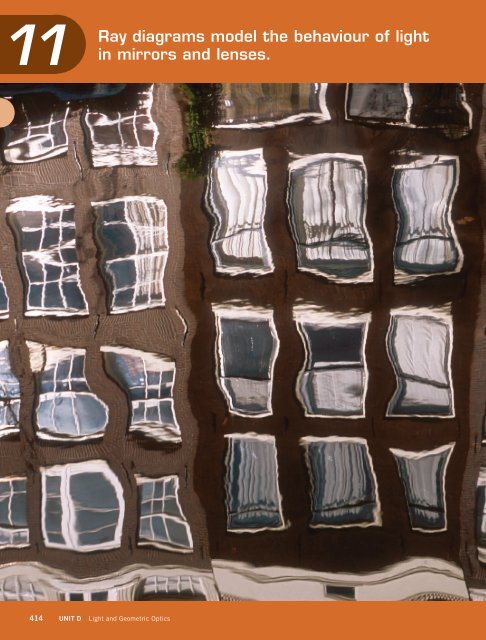
11Ray diagrams model the behaviour of lightin mirrors and lenses.414 UNIT D Light and Geometric Optics
Skills You Will UseIn this chapter, you will:Buildings reflected in an Amsterdam canal• investigate the laws of reflection using plane and curvedmirrors• predict characteristics of images formed by mirrors and testthose predictions• investigate the refraction of light• use ray diagrams and equations to predict position andcharacteristics of images formed by lenses• calculate the velocity of light as it refracts through differentmediaConcepts You Will LearnIn this chapter, you will:• describe images formed by mirrors and lenses• explain partial and total reflection and refraction• identify the factors that affect refraction as light passes fromone medium to anotherWhy It Is ImportantOur understanding of light as a ray that travels in a straight linehas led to the invention of mirrors and lenses that perform avariety of functions. Learning about light will help youunderstand, select, and use optical devices and vision aids.Before ReadingReading DiagramsDiagrams provide a lot of information, often in a small format.You may have to read diagrams differently from word text.Skim this chapter, and preview the diagrams. How are theysimilar to and different from each other? What are someimportant features that may help you to understanddiagrams?Key Terms• angle of incidence • angle of reflection • angle of refraction• concave • convex • focal length • focal point • magnification• mirage • normal refraction • virtual imageRay diagrams model the behaviour of light in mirrors and lenses. 415
11.1MirrorsHere is a summary of what youwill learn in this section:• The angle of incidence equalsthe angle of reflection.• Plane mirrors produce a virtualimage that is upright andlocated as far behind the mirroras the reflected object is infront of it.• Concave mirrors produce anenlarged, upright, virtual imageif the object is closer to themirror than the focal point.• Concave mirrors produce aninverted, real image if theobject is farther away from themirror than the focal point.• Convex mirrors produce anupright, virtual image that issmaller than the object.Figure 11.1 The stainless steel mirror above Viganella is controlled by computer to follow thepath of the Sun.Figure 11.2 The construction of the mirrorBrightening a Winter’s DaySummer in the Italian village of Viganella high in theItalian Alps is peaceful, warm, and above all — sunny.But winter is another story. As the hours of daylightshrink each autumn and the Sun spends less and less timeabove the horizon each passing day, Viganella loses itsdirect view of the Sun. Viganella is located at the bottomof a steep valley, and every winter the mountains blockout the Sun’s rays from November 11 to February 2.During this time, the village is completely in themountain’s shadow.But thanks to the science of optics, that situation hasnow changed. In 2006, a large flat mirror was placed atthe top of one of the nearby mountains and directed at thevillage square (Figure 11.1). Airlifted into position with ahelicopter at a total cost of about $170 000, the 5 m 8 mrectangular sheet of stainless steel is perched high aboveViganella (Figure 11.2).416 UNIT D Light and Geometric Optics
During ReadingDiagrams RequireSpecial Reading TechniquesYou cannot always read diagramsthe way you read words, left toright and top to bottom. Look atthe whole diagram first. Then,read the caption, and look againat the diagram. Let your eye followthe flow of the diagram. Are therearrows? Are there labels? What dothey tell you? After examining thediagram, make notes about whatyou learned from it.The Law of ReflectionSmooth, shiny surfaces like calm water, mirrors, glass, and evenpolished metal allow you to see an image. The smoother the surface is,the better the image will be. An image is a reproduction of an objectproduced by an optical device like a mirror. An optical device is anytechnology that uses light.Light rays bounce off a mirror in a similar way to how a hockeypuck bounces off the boards of an ice rink. To understand how lightbehaves when it reflects off a mirror, it helps to look at the reflection ofa single ray of light in a ray diagram (Figure 11.4).angle ofincidencenormalirangle ofreflectionmirrorFigure 11.4 If the angle of incidence equals 45°, then the angle of reflection is also 45°.WORDS MATTERThe word normal comes from theLatin word norma, meaning acarpenter’s square.The dashed line drawn perpendicular to the mirror at the point ofreflection represents an imaginary line called the normal. Theincoming ray is called the incident ray. The angle between theincident ray and the normal is called the angle of incidence, labelled i.The angle between the reflected ray and the normal is called the angleof reflection, labelled r. The relationship of thesetwo angles is one of the most important propertiesof light, called the law of reflection:When light reflects off a surface, the angle ofincidence is always equal to the angle ofreflection.Figure 11.5 The mirrors in a bicycle tail light reflect headlightbeams back to the driver of the car that sent them.Although the law of reflection may appear verysimple, it is also very useful. For example, the lawof reflection is used to design reflective tail lightsfor bicycles. A tail light is designed to reflect lightfrom the headlights of the car behind it. This helpsto make the bicycle more visible to the driver of thecar. The ray diagram in Figure 11.5 shows how twomirrors arranged at an angle of 90° can use tworeflections to send reflected rays back in the samedirection as the incident rays, no matter where theincident rays come from. In each reflection, theangle of incidence equals the angle of reflection.418 UNIT D Light and Geometric Optics
Using the Law of ReflectionThe law of reflection can be written using mathematical symbols. TheGreek letter theta, θ, is commonly used as the symbol for an angle.Subscripts are used to identify the angle. If the angle of incidence is θ iand the angle of reflection is written as θ r, then the law of reflection is:Suggested Activity •D13 Quick Lab on page 428θ i= θ rThe angle of incidence and the angle of reflection are alwaysmeasured from the normal and not from the surface of the object. Thisis because some surfaces are curved, making it difficult to measure anangle from the surface.Plane MirrorsThe law of reflection applies to light rays reflected from both flatmirrors and curved mirrors. Any mirror that has a flat reflective surfaceis called a plane mirror. When you look into a plane mirror, yourimage appears to be as far behind the mirror as you are in front of it. Infact, the mirror may appear to be a kind of glass window. However, it isnot possible to catch this image on a piece of paper placed behind themirror, since no light from the object reaches this point. Because thelight rays are not coming from where your image appears to be, we saythat your image in a plane mirror is a virtual image. A virtual image isany image formed by rays that do not actually pass through the locationof the image (Figure 11.7 below).Image Orientation in a Plane MirrorWhen you look in a mirror, your left hand appears to be a right hand. Ifyou hold a textbook up to a mirror, you will notice that the text appearsto be reversed. Sometimes, emergency vehicles are labelled in reverseprinting so their signs can be read in a car’s rear-view mirror, as inFigure 11.6.The ray diagram in Figure 11.7 shows why this happens.To understand how the image forms, we draw a few rays fromvarious points on the girl’s face, and reflect them into hereyes. There is only one rule — the rays must follow the law ofreflection. Once we have done this, we have shown the actualpath of the light rays.What does the girl see? To find out, we can extend thereflected rays back in a straight line behind the mirror toform the virtual image. So when the girl looks in the mirror,the image of her right eye is directly in front of her right eyein the virtual image. If she lifted her left arm, the arm in thevirtual image would lift directly in front of it. The virtualimage is an exact reflection of the real object.Figure 11.6 Reverse printing will beread normally when viewed in amirror.Figure 11.7 A ray diagram shows how avirtual image forms in a plane mirror.Ray diagrams model the behaviour of light in mirrors and lenses.419
Suggested Activity •D16 Problem-Solving Activity on page 432Learning Checkpoint1. What is the difference between a reflected ray and an incident ray?2. (a) What does the law of reflection state in words?(b) Write the law of reflection using mathematical symbols.3. What is a plane mirror?4. What is a virtual image?Figure 11.8 A reflection produced bya mirror with several curvesray 2ray 1h oF vertexobjectfh iimageFigure 11.9 A ray diagram for a converging mirrord id oCurved MirrorsThe strange image you see in a funhouse mirror is produced by a mirrorthat has flat, outward-curved, and inward-curved sections in it asshown in Figure 11.8. While they may be fun to look at, mirrors withmultiple curves have no real practical uses. However, mirrors with asingle curvature find many uses in our homes and optical devices. Twotypes of curved mirrors are concave (converging) and convex(diverging).Curved Mirror TerminologyLike plane mirrors, curved mirrors obey the law of reflection. However,when parallel light rays strike a curved surface, each ray of light willreflect at a slightly different position. All of these rays eventually meetat a common point. The point where light rays meet, or appear to meet,is called the focal point, F (Figure 11.9).The middle point of a curved mirror is called the vertex. Theprincipal axis is an imaginary line drawn through the vertex,perpendicular to the surface of the curved mirror. The distance betweenthe vertex and the object is represented by d o. The distance between thevertex and the image is d i. The height of theobject is h o, and the height of the image is h i.The focal length, f, is the distance from thevertex to the focal point of a curved mirror. If theobject is farther away from the mirror than thefocal point, the reflected rays form a real image.A real image is an image formed by light raysprincipalaxisthat converge at the location of the image. If youplace a piece of paper at the spot where a realimage forms, a focussed image would appear onthe paper or screen. If the screen were movedslightly, the image would appear blurred becausethe reflected rays would not be converging at thescreen’s new location.420 UNIT D Light and Geometric Optics
Concave MirrorsA concave mirror, also called a converging mirror, has a surface thatcurves inward like a bowl (Figure 11.10). The image formed by aconcave mirror depends on how far the object is from the focal point ofthe mirror. If the object is far away from the focal point, the reflectedrays form an inverted image as shown in Table 11.1. The closer theobject gets to the focal point, the larger the image becomes. If the objectis between the focal point and the mirror, like the bird in Figure 11.11,the image becomes upright and enlarged. When the object is exactly atthe focal point, all rays that leave the object reverse direction at themirror and are reflected away from the mirror parallel to each other. Inthis case, no image is formed.FimageFigure 11.10 Parallel light rays approaching a concave mirror.Figure 11.11 A virtual image produced by a converging mirror.The bird is between the focal point and the mirror so the virtualimage is larger than the real bird.Table 11.1 Ray Diagrams for Concave MirrorsDistance of Objectfrom Mirror, d oType of ImageFormedHow the ImageIs ViewedRay DiagramObject is more thantwo focal lengths.Smaller than object,inverted, realThe mirror can projectan image on a screenplaced in front of themirror.objectFObject is between oneand two focal lengths.Larger than object,inverted, realThe mirror can projectan image on a screenplaced in front of themirror.objectFObject is at focal point. No image is formed. No image is formed. objectFObject is betweenmirror and focal point.Larger than object,upright, virtualViewer looks into themirror to see theimage.FobjectRay diagrams model the behaviour of light in mirrors and lenses.421
Drawing a Concave Mirror Ray DiagramWhen you draw ray diagrams, you can sketch in the object or use anupright arrow to represent the object, as shown in Figure 11.12. Showreal rays as solid lines. Use dashed lines to present virtual rays, whichare rays that only appear to exist behind the mirror. Follow the steps inFigure 11.12 to draw a ray diagram of a concave mirror.ray 1ray 2FobjectimageFigure 11.12 Concave mirror ray diagram1. The first ray of a concave mirror ray diagramtravels from a point on the object parallel to theprincipal axis (ray 1). Any ray that is parallel tothe principal axis will reflect through the focalpoint on a converging mirror.2. The second ray travels from a point on theobject toward the focal point (ray 2). Any raythat passes through the focal point on aconverging mirror will be reflected back parallelto the principal axis.3. Draw the real image where the rays intersect.Some Uses for Concave MirrorsConcave mirrors are specially designed to collect light and bring it to asingle point. This is why concave mirrors are used in telescopes tocollect light rays from a great distance and bring them together.Can concave mirrors be used to send out beams of light rays as well?Imagine that a bright light were placed at the focal point of a concavemirror and allowed to shine into the mirror in Figure 11.10 on theprevious page. By reversing the direction of the arrows in the ray diagram,you can see that the light rays would leave the mirror as parallel rays.That is why you will find concave mirrors in flashlights, car headlights,dental examination lights, and other applications (Table 11.2).Table 11.2 Some Uses of Concave MirrorsDeviceFlashlightUse of Concave MirrorTo produce a parallel beamTelescopeTo collect light from a distant source andfocus it for viewingFigure 11.13 The concave mirror forthe Hubble telescope is beingprepared for launch into space.Cosmetic mirrorHeadlightsof a carTo produce an enlarged imageTo produce a parallel beam of light that canbe directed down (low beam) or straightahead (high beam)422UNIT DLight and Geometric Optics
Solar OvensA solar oven, also called a solar cooker, is adevice that uses light from the Sun as its energysource. A solar oven transforms sunlight directlyinto heat that can be used for cooking or boilingwater (Figures 11.14 and 11.15). By making use ofsolar energy, precious resources can be saved. Forexample, trees are scarce in the Himalayas andusing solar energy instead of wood for heat helpspreserve forests.A solar oven uses several strategies forproducing heat, such as using a concave mirror toconcentrate the Sun’s rays, converting light toheat through absorption if the interior of the ovenis a dark colour, and using a clear cover so thatthe Sun’s rays can enter but very little heat canleave. The most efficient ovens create aninsulated space where the food is cooked.Figure 11.14 A man examines a solar oven that is heating water inLadakh, high in the Himalayan Mountains.Calculating MagnificationConcave mirrors have a number of usesincluding magnification. Magnification is themeasure of how much larger or smaller an imageis compared with the object itself. Themagnification of an image, as compared with theobject, may be the same size, enlarged, ordiminished (smaller). Magnification is expressedas a ratio of the height of the image to the heightof the object.Figure 11.15 This solar oven is located on a city rooftop.magnification =image heightobject heightorhM = ih oMagnification can also be determined by taking the ratio of thedistance from the image to the mirror and the distance from the objectto the mirror.Suggested Activity •D15 Inquiry Activity on page 430image distancedmagnification = or M = iobject distanced oThese are very general definitions of magnification. You can useeither formula to determine magnification. Be sure to use the sameunits for both heights or both distances in the calculation. However, nounits are required in the answer since the units cancel out during thecalculation. If the image is bigger than the object, then themagnification will be greater than 1. If the image is smaller than theobject, the magnification will be less than 1.Ray diagrams model the behaviour of light in mirrors and lenses.423
Practice Problems1. A microscope produces animage that is 1.00 × 10 –4 mhigh from an object that is4.00 × 10 –7 m high. What isthe magnification of themicroscope?2. A concave mirror producesan image on a wall that is30.0 cm high from an objectthat is 6.5 cm high. What isthe magnification of themirror?3. A pinhole camera producesa 2.34 × 10 –2 m image of abuilding that is actually50.0 m high. What is themagnification of the camera?Example Problem 11.1A microscope produces an image that is 5.50 × 10 –4 m high froman object that is 2.00 × 10 –6 m high. What is the magnification ofthis microscope?GivenObject height h o= 2.00 × 10 –6 mImage height h i= 5.50 × 10 –4 mRequiredMagnification M = ?Analysis and SolutionThe correct equation is M =Substitute the values and their units, and solve the problem.M =h ih o5.5 10 –4 mM =2.00 10 –6 m= 275h ih oParaphraseThe magnification of the microscope is 275 times.Practice Problems1. An object is placed 75 cmfrom a concave mirror. Areal image is produced50 cm away. What is themagnification?2. A person standing 3.00 mfrom a glass window seesher virtual image 3.00 m onthe other side. What is themagnification of thewindow?3. A camera creates a realimage of a tree 40 m away.The image is formed 3.0 cmbehind the lens. Find themagnification.Example Problem 11.2A candle is placed 22 cm from a concave mirror. A virtual image isproduced 53 cm from the mirror. What is the magnification?GivenObject distance d o= 22 cmImage distance d i= 53 cmRequiredMagnification M =?Analysis and SolutionThe correct equation is M =Substitute the values and their units, and solve the problem.M =d id o53 cmM =22 cm= 2.4d id oParaphraseThe magnification of the mirror is 2.4 times.424 UNIT D Light and Geometric Optics
Example Problem 11.3An electron microscope magnifies a virus that is 3.50 × 10 –7 m. Ifthe magnification is 3.70 × 10 5 , how big will the image be?GivenObject height h o= 3.50 × 10 –7 mMagnification M = 3.70 × 10 5RequiredImage height h i= ?Analysis and SolutionThe correct equation is M =h ih oRearrange it to solve for the variable needed: h i= Mh oSubstitute the values and their units, and solve the problem.h i= Mh oh i= (3.70 × 10 5 )(3.50 × 10 –7 m)= 0.130 mParaphraseThe size of the image is 0.130 m or 13.0 cm.Practice Problems1. A slide projector has amagnification of 50. Howwide will the projectedimage be if the slide is2.8 cm wide?2. A concave mirror creates avirtual image of a candleflame that is 10 cm high. Ifthe magnification of themirror is 12.5, what is theheight of the candle flame?3. A magnifying glass willmagnify 6 times. If themagnifying glass is heldover a page and magnifiesa letter that is 2 mm tall,how big is the image?Example Problem 11.4A concave mirror creates a real, inverted image 16.0 cm from itssurface. If the image is 4.00 times larger, how far away is the object?GivenImage distance d i= 16.0 cmMagnification M = 4.00RequiredObject distance d o= ?Analysis and SolutionThe correct equation is M = d id oRearrange it to solve for the variable needed: d o=Substitute the values and their units, and solve the problem.d id o=Md o= 16.0 cm4.00= 4.00 cmd iMPractice Problems1. An insect is magnified12 times by a concavemirror. If the image is real,inverted, and 6 cm fromthe mirror, how far away isthe insect?2. A lens produces a realimage that is 23 timesbigger than the object. Ifthe object is 14 cm away,how far away is the image?3. A human hair is placed3 mm from a powerfulmicroscope lens that has amagnification of 40 times.How far from the lens willthe image be formed?ParaphraseThe object is 4.00 cm from the mirror.Ray diagrams model the behaviour of light in mirrors and lenses.425
FConvex MirrorsA mirror with a surface curved outward is a convex mirror, also calleda diverging mirror (Figure 11.16). Instead of collecting light rays, aconvex mirror spreads out the rays. A convex mirror produces a virtualimage that is upright and smaller than the object (Figure 11.17). Theimage is a virtual image because although the reflected rays appear to beoriginating from behind the mirror, if a screen were placed there, theincident light rays would not reach it. The rays would be blocked by themirror.Figure 11.16 Parallel light raysapproaching a convex mirrorimageFigure 11.17 A virtual imageproduced by a diverging mirroris smaller than the object.Table 11.3 Ray Diagram for Convex MirrorDistance of Objectfrom Mirror, d oType of ImageFormedHow the Image IsViewedRay DiagramAll distances infront of the mirrorSmaller thanobject,upright,virtualBehind the mirrorbetween the vertexand the focal pointray 1ray 2Fray 1ray 2Figure 11.18 Convex mirror ray diagramDrawing a Convex Mirror Ray DiagramYou can follow the steps in Figure 11.18 to draw a ray diagram of aconvex mirror.F1. The first ray of a convex mirror ray diagramtravels from a point on the object parallel tothe principal axis (ray 1). Any ray that isparallel to the principal axis will appear tohave originated from the focal point on adiverging mirror.2. The second ray travels from a point on theobject toward the focal point (ray 2). Anyray that is directed at the focal point on adiverging mirror will be reflected backparallel to the principal axis.3. Draw the virtual image where the raysappear to intersect.426UNIT DLight and Geometric Optics
Uses for Convex MirrorsIf you were to compare a convex mirror with a plane mirror of the samesize, you would discover that more objects can be seen in the convexmirror. For this reason, convex mirrors are often used as securitymirrors in stores (Figure 11.19). A convex mirror allows you to view alarge region of the store from one location. For the same reason, convexmirrors are used in vehicles as side-view mirrors and rear-view mirrors.However, if you look in a convex mirror, it appears as if the image isoriginating from a smaller point behind the mirror. Because of thesesmaller images, convex mirrors on cars often have a warning such asthe one shown in Figure 11.20 that objects in the mirror are closer thanthey appear.You may have noticed convex mirrors used in some automatic tellermachines and computers (Figure 11.21). A convex mirror allows themachine users to see what is happening behind them while they arefacing the machine screen. Many camera phones include a convexmirror so that you can accurately aim the camera to take a self-portrait.Figure 11.19 A store security mirror Figure 11.20 A side-view mirror Figure 11.21 A security mirror on anautomatic teller machineLearning Checkpoint1. What is a real image?2. What is a virtual image?3. Name the features of the ray diagram identified as A, B, C, and D.DACBTake It FurtherThe first astronaut to walk on theMoon, Neil Armstrong, put aspecial mirror on the Moon’ssurface that was able to reflectlight directly back in the directionfrom which it came. Scientistsfrom Earth shine laser light at thismirror. Find out how this mirrorworks and what has been learnedfrom pointing a laser from Earth atthe mirror. Begin your research atScienceSource.4. Draw a ray diagram where the object is between one and two focal lengthsfrom a concave mirror with a focal length of 5 cm.5. Draw a ray diagram where the object is more than two focal lengths from aconcave mirror with a focal length of 5 cm.Ray diagrams model the behaviour of light in mirrors and lenses.427
D13 Quick LabPlane Mirror ReflectionThe reflective surface of the mirror may be at the backof the mirror or at the front of the mirror dependingwhere the reflective coating was applied to the glass orplastic you are using.PurposeTo investigate the law of reflection using a plane mirrorMaterials & Equipment• ruler• paper• protractor• plane mirrorProcedure• ray box or light sourcethat can be made intoa single 1-mm wideslit sourceCAUTION: Do not shine bright light into anyone’s eyes.Incandescent light sources can become very hot. Do nottouch the bulbs or block air flow around the light bulbs.1. Use the ruler to draw a straight vertical line in themiddle of a piece of paper. Use the protractor tocreate a perpendicular normal at the approximatecentre of the first line.2. Place the mirror upright along the vertical line.Hold the mirror in place. The normal should beperpendicular to the surface of the mirror.3. Shine a ray of light at an acute angle to the normalso that it reflects where the normal meets thereflecting surface. Use the ruler to trace theincident ray between the light source and themirror. Then, trace the reflected ray that reflectsfrom the mirror.4. Label the incident ray as i 1. Label the reflected rayas r 1(Figure 11.22).5. Repeat step 2 two more times with differentangles. Be sure to label the successive incidentand reflected rays as i 2, r 2and i 3, r 3.6. Measure and record the angle between each lightray and normal.Questions7. Compare the results of the angles of incidenceand reflection. Describe how they are related.8. (a) Are your results exactly the same as the law ofreflection? Explain.(b) What aspects of your experimental methodcould make your results different from the lawof reflection?90°reflecting surface(mirror)i 1incident rayθ i1θ r1Figure 11.22 A sample drawingnormalreflected rayr 1428 UNIT D Light and Geometric Optics
D14 Skill Builder ActivityDrawing Ray Diagrams for Concave and Convex MirrorsConcave Mirrors1. Copy Figure 11.23(a) into your notebook.Convex Mirrors1. Copy Figure 11.24(a) into your notebook.concave mirrorconvex mirrorobjectFobjectFFigure 11.23(a) Draw the object and the mirror.2. To determine where the image of the tip of thearrow will be, draw two rays. Draw the first rayparallel to the principal axis until it strikes themirror and reflects through the focal point(Figure 11.23(b)).concave mirrorFigure 11.24(a) Draw the object and mirror.2. Draw the first ray parallel to the principal axis until itstrikes the mirror, where it reflects away in a line thatappears to come from the focal point. Draw adashed line from the point on the mirror where theray strikes through the focal point (Figure 11.24(b)).convex mirrorobjectobjectFFFigure 11.23(b) Draw the first ray.3. Draw the second ray through the focal point untilit strikes the mirror and reflects parallel to theprincipal axis (Figure 11.23(c)).objectFconcave mirrorFigure 11.23(c) Draw the second ray.4. These two rays intersect at only one location. Thisis where the image of the tip of the arrow is. Drawthe inverted image (Figure 11.23(d)).objectimageFconcave mirrorFigure 11.23(d) Draw the inverted real image.5. Repeat the process for other parts of the object.Figure 11.24(b) Draw the first ray.3. Draw the second ray toward the mirror heading for thefocal point until it strikes the mirror and reflects backparallel to the principal axis. Draw a dashed linethrough the mirror parallel to the principal axis until itintersects the first dashed line (Figure 11.24(c)).objectconvex mirrorFigure 11.24(c) Draw the second ray.4. The intersection of both dashed lines represents thevirtual image of the tip of the arrow. The image for aconvex mirror is always virtual, upright, and smaller.objectFconvex mirrorimageFFigure 11.24(d) Draw the upright, virtual image.Ray diagrams model the behaviour of light in mirrors and lenses.429
DIKey ActivityD15 Inquiry ActivityConcave MirrorsQuestionHow does the distance of the object from a concavemirror affect the size and orientation of the image?Materials & Equipment• 2 optical benches• good quality concave mirror with a predeterminedfocal length• light source, such as candle or light bulb• metre stick with millimetres marked• screenCAUTION Light Bulb: Do not shine bright light intoanyone’s eyes. Incandescent light sources can becomevery hot. Do not touch the bulbs or block air flow aroundthe light bulbs.Candle: Tie back long hair, secure loose clothing, andavoid sudden movement when using candles. Make surethe candle is in a secure holder. Be careful not to get thescreen too close to the flame. Be careful when moving thecandle so you are not burned by a drop of melted wax.Dispose of all matches in an appropriate location.Skills References 2, 8ProcedureSKILLS YOU WILL USE■ Gathering, organizing, andrecording relevant data frominquiries■ Processing and synthesizingdata1. Copy Table 11.4 into your notes. Record the focallength of your concave mirror as supplied by yourteacher in the table title.2. Set up the first optical bench with the concavemirror at one end and the light source at the otherend. The concave mirror should be angled slightlyaway from the light.3. Light the candle, or turn on the light bulb. Darkenthe room. Align a second optical bench with ascreen so that the reflected image of the lightstrikes the screen, as shown in the diagram. Itdoes not need to be in focus yet. The opticalbenches are now aligned and should not bemoved (Figure 11.25 on the next page).Table 11.4 Concave Mirror Focal Length: _______Distance of Candle fromMirrorObjectDistance d o(cm)ImageDistance d i(cm)Orientation(uprightor inverted)ObjectHeight h o(cm)ImageHeight h i(cm)Magnification3 times the focal length2 times the focal length1.5 times the focal lengthFocal length0.5 of the focal length430 UNIT D Light and Geometric Optics
D15 Inquiry Activity (continued)Figure 11.25 Step 34. Move the candle to the distance indicated in thefirst row of the table in the “Distance of Candlefrom Mirror” column. Write this actual distanceinto the table in the “Object Distance d o” columnthat is beside it.5. Slowly move the screen along the length of thebench until the image of the candle flame comesinto focus. Measure the distance from the mirrorto the screen. Record this distance as the imagedistance, d iin the table. Record the orientation ofthe flame in the table.6. Very carefully measure the size of the actual flameor bulb and the height of the image of the light.Record these values in your chart.7. Repeat steps 4 to 6 for the next distance indicatedin the table, until all rows of the table arecomplete.Analyzing and Interpreting8. How do you explain the results obtained when theobject was placed at 0.5 of the focal length fromthe mirror?Skill Practice9. Complete the magnification column of the table.Show one of your calculations.Forming Conclusions10. Using the completed table, form a conclusionabout:(a) the magnification of the image based on theobject’s distance from the mirror(b) the orientation of the image based on theobject’s distance from the mirrorRay diagrams model the behaviour of light in mirrors and lenses.431
D16Problem-Solving ActivityLaser Light Security SystemSkills References 3, 6SKILLS YOU WILL USE■ Identifying sources of error■ Expressing results accuratelyand preciselyRecognize a NeedThe local museum is displaying a number of pricelessartifacts in two adjoining rooms that are connected byan open door (Figure 11.26). Security is provided by alaser light and light sensor combination.Figure 11.26 A floor planof the museumProblemHow can you set up a security system using the laserand the light sensor?Materials & Equipment• 2 empty shoe boxes• tape• piece of paper60 cm 60 cm and2 cm 2 cm• protractorCriteria for Success• The laser light must enter one of the rooms fromwhichever direction you choose, through a smallopening in the side of the room. It must bounce offall the windows and the outside doors. Finally, itmust hit a 2 cm 2 cm piece of paper attached tothe wall of the last room that represents the alarmsensor.Brainstorm Ideas• ruler• selection of smallplane mirrors• modelling clay• Class 1 or 2 laserCAUTION: Do not shine the laser light in anyone’s eyes.1. Brainstorm how to arrange plane mirrors withinthe rooms (shoe boxes) so that the light ray fromthe laser will bounce off every window and the twooutside doors and hit the paper alarm sensor.Make a Drawing/Build a Model2. Firmly tape the two shoe boxes together in theorientation shown in Figure 11.26. Place the shoeboxes on a large piece of white paper and tracetheir outlines. Remove the boxes and draw thelocation of the windows and doors on the paper.3. Plan the location of the mirrors based on theposition of the doors and windows. Use aprotractor and ruler to draw in the mirrors at theproper location and angle so the light ray willbounce off all the windows, the two outside doors,and finally the white paper sensor in the lastroom.4. Use the ruler to draw a line on the paper thatshows the path of the light ray as it moves throughthe rooms.5. Build a 3D model of the rooms using the shoeboxes. Attach plane mirrors to the walls in theproper positions to represent the windows and thetwo outside doors.6. Position the alarm sensor in your model.Test and Evaluate7. Have your teacher use a laser to test theeffectiveness of your alarm system. Makeadjustments to the mirrors as needed.Skill Practice8. How accurate did you have to be in placing yourmirrors so the beam reflected properly?9. What strategies did you use to ensure accurateplacement?10. How could you improve your solution?Communicate11. How well did the drawing of the mirrors and theirangles correspond to what actually happened?432 UNIT D Light and Geometric Optics
11.1 CHECK and REFLECTKey Concept Review1. Describe the law of reflection as arelationship between the angle of incidence,the angle of reflection, and the normal.2. Describe the kinds of images that can beformed by plane mirrors.3. (a) What type of mirror produces onlydiverging rays?(b) What type of mirror can produce bothconverging and diverging rays?4. Describe what kind of mirror you would useif you needed to view a large, spread-out areain a small mirror.5. Compare the shapes of convex and concavemirrors. How are they similar, and how dothey differ?6. What kind of images do convex mirrors form?7. What are three uses for convex mirrors?8. A lighted object is placed at the focal point ofa concave mirror. Describe the light raysreflecting off the mirror.Connect Your Understanding13. Use a ray diagram with five rays to show howa car headlight uses a concave mirror to directlight.14. Draw the following ray diagram: three rays,travelling generally left to right, converge10 cm away from a concave mirror and arereflected away from the mirror as parallelrays.15. Draw a ray diagram to determine the positionof an image formed by a concave mirror thathas a focal length of 3.0 cm and a 2.0 cmobject positioned 6.0 cm from the mirror.16. If you can see someone in a mirror, can thatperson see you? Explain why or why not. Usea ray diagram if necessary.17. Draw a view from above of an arrangement ofmirrors that would allow you to see the backof your head. Mark the angles of incidenceand reflection on your diagram.18. Does diffuse reflection, shown below, followthe law of reflection? Explain why it does ordoes not.9. Describe how the positions of a mirror,incident ray, reflected ray, and normal arerelated.10. How does your image in a mirror comparewith looking directly at yourself?11. A bacterium has a length of 5.5 10 –6 m butseen through a powerful microscope appearsto be 1.2 10 –3 m. What is the magnificationof the microscope?12. A virtual image is produced by a convexmirror that is 1.60 cm from the mirror. If themagnification is 0.20, how far from themirror is the object?Question 18Reflection19. (a) Describe one idea you found easy to learnin this section.(b) Why do you think it was easy to learn?(c) Describe one idea you found difficult tounderstand in this section.(d) What did you do to help yourselfunderstand it?For more questions, go to ScienceSource.Ray diagrams model the behaviour of light in mirrors and lenses.433
11.2The Refraction of LightHere is a summary of what youwill learn in this section:• Refraction is the bending oflight as it passes betweenmedia that have differentrefractive indices.• Refraction occurs due to thechange in the speed of light indifferent media.• The index of refraction of amedium is the ratio of thespeed of light in a vacuumcompared to the speed of lightin the medium.• As light passes at an anglefrom a less dense medium intoa more dense medium, thelight ray bends toward thenormal.• Snell’s law relates the indicesof refraction of a medium to theangle of incidence andreflection.Figure 11.27 Laser light is transmitted along optical fibres for use in surgery.Fibre OpticsOne of the most important properties of light is that it tends to travel instraight lines. If you need light to bend around a corner or to shine intoa difficult-to-reach place, you might want to use optical fibres. Anoptical fibre is a thin, transparent glass tube that can transmit lighteven around corners (Figure 11.27). This is because the light in a fibreoptics tube cannot escape until it reaches the end of the tube.How does an optical fibre conduct a light ray around a corner?Imagine a long, curved tunnel whose walls, floor, and ceiling are linedwith mirrors. If you were to shine a laser beam into the tunnel, thebeam of light would change direction each time it reflected from amirror and would make it all the way to the end of the tunnel. This isexactly what happens on the inside of the optical fibre. The light rayreflects off the inside of the walls of the glass fibre. When the thin glassfibre bends around a corner, the light ray goes around the cornerthrough a series of reflections.434 UNIT D Light and Geometric Optics
We use fibre optics systems to transmittelephone and Internet communications. A singleoptical fibre can be as thin as a human hair, yettransmit thousands of different signals at the sametime (Figure 11.28). This is because each signal issent at a different wavelength through the samecable. Just as two flashlight beams can cross eachother and then continue on their way unaffected,thousands of light beams can pass through the samecable. A typical optical fibre cable can be made fromthousands of optical fibres tightly packed together.Figure 11.28 A single optical fibre can fit through the eyeof a needle.D17 Quick LabObserving RefractionPurposeTo observe whether the bending of light affects theway we see certain objectsMaterials & Equipment• glass of water• pencil• jar lid with opaque rim• coinProcedure1. Insert a pencil into the glass of water. Observe theglass from the side at various angles. Record yourobservations using labelled diagrams.2. Place a jar lid with an opaque rim on a desk andput a coin in the middle.3. Keep watching the coin while you lower theheight of your head until the coin just disappearsfrom view behind the rim of the lid (Figure11.29).4. Keeping your head at the same level, pour waterinto the lid, on top of the coin. Observe. Recordyour observations using labelled diagrams.Figure 11.29 Step 3Questions5. Describe the path of light from the water to theair.6. Draw a ray diagram of the light rays from the cointo your eye:(a) in step 3(b) in step 47. Compare your drawings in question 6 with thosedone by classmates.(a) How are your drawings similar?(b) How are your drawings different?Ray diagrams model the behaviour of light in mirrors and lenses.435
RefractionFigure 11.30 The spoon appears tobe broken because light rays changedirection as they move from air intowater and from water into air.Although light travels in straight lines, it bends when it passes fromone medium into another, such as from air into water. A medium(plural: media) is a material that is being used or is undergoing aprocess. The bending of light rays as they pass between two differentmedia is called refraction. Refraction causes some very interestingvisual effects. For example, the handle of the spoon in Figure 11.30appears to be broken at the level of the top of the water. When lightfrom the spoon passes from the water into the air, the light rays arebent. Refraction is more than just an optical curiosity. It is used indesigning and building camera lenses, eyeglasses, and telescopes.Refraction is due to changes in the speed of light. For example, aslight moves from air into water, its speed decreases. Different mediaslow down light by different amounts. The more that light slows down,the more the light is refracted.You may have stood beside a pool or lake and seen something on thebottom that you wanted to pick up. Yet, when you dove in, the objectwas not where it appeared to be. This is because the light rays changeddirection at the surface of water as they passed between the water andthe air. Figure 11.31 shows light rays moving from water into air andrefracting as they leave the water. When we view the refracted lightrays, we assume they have travelled in a straight line. If you trace thelight rays that reach the eyes back in a straight line, you will find thatthey do not lead to the chest. Instead, the light from the chest in deepwater appears to be coming from shallower water.During ReadingPurpose of anIllustrationState the topic and purpose for theillustrations on these and thefollowing pages in this section. Findwords in the caption that also occurin the text. Write a statement abouthow the illustration helps you tounderstand a concept or idea.water surfaceimage of chestactual chestFigure 11.31 The underwater chest appears to be higher than it really is.The Speed of LightIn the vacuum of space, where there are very few particles, light travelsat almost 300 million m/s or 3.0 × 10 8 m/s. Moving at this speed, lightcould travel seven times around the Earth in one second. However, justlike a student trying to move from class to class when the hallways arefull, it is impossible for light to move at top speed when particles get inthe way.436 UNIT D Light and Geometric Optics
A ray of light is electromagnetic radiation, whichis transmitted in waves. The particles in a mediumslow down the passage of the waves, which results inlight travelling more slowly through a block of glass,for example, than it travels through a vacuum.The effects of changes in the speed of light can beseen in Figure 11.32. The light ray strikes thePlexiglas at an angle. As the light enters the Plexiglas,it slows down and refracts (a). When the light leavesthe Plexiglas and enters the air, it speeds up andrefracts again (b). Notice that light does not refractinside the block. Light refracts only at the boundarywhen it is entering or leaving a medium. Thisphotograph also shows that refraction is a reversibleprocess, in that the angle of refraction entering the block is exactlyreversed as the light leaves the block. The light ray immediately speedsup again as it leaves the block.aFigure 11.32 Light refracts as it enters and then leaves this blockof Plexiglas.bThe Index of RefractionThe amount by which a transparent medium decreases the speedof light is indicated by a number called the index of refraction,also called the refractive index. The larger the refractive index,the more the medium decreases the speed of light.Light travels fastest in a vacuum. The refractive index of thespeed of light in a vacuum is assigned a value of 1.00. A value of1.00 can also be used for air, since the fourth decimal place doesnot affect calculations based on Table 11.5. Since water, glass,diamond, and other media all slow down light, they have highervalues than air.The refractive index of a medium, n, is determined bycomparing the speed of light in the medium, v, with the speed oflight in a vacuum, c. This leads to the following definition:speed of light in vacuumindex of refraction of material =speed of light in mediumcor n =vSince units cancel, a refractive index value does not haveany units.Table 11.5 Index of Refraction forSelected MediaMediavacuumIndex of Refraction1.00 (exactly)air 1.0003carbon dioxide gas 1.0005water 1.33alcohol 1.36Pyrex glass 1.47Plexiglas 1.49table salt 1.51flint glass 1.61sapphire 1.77cubic zirconia 2.16diamond 2.42gallium phosphide 3.50Ray diagrams model the behaviour of light in mirrors and lenses.437
Practice Problems1. The speed of light in leadedglass is 1.66 × 10 8 . What isthe index of refraction ofthis type of glass?2. The speed of light in quartzis 2.10 × 10 8 m/s. What isthe index of refraction ofquartz?3. The speed of light through amaterial is 1.24 × 10 8 m/s.What material is it?(Hint: Refer to Table 11.5on page 437.)Example Problem 11.5The speed of light in a sample of glass is 1.91 × 10 8 m/s. The speedof light in a vacuum is 3.00 × 10 8 m/s. What is the refractive indexof this glass?GivenSpeed of light in glass = 1.91 × 10 8 m/sSpeed of light in vacuum = 3.00 × 10 8 m/sRequiredRefractive index n = ?Analysis and SolutionThe correct equation is n =cvSubstitute the values and their units, and solve the problem.n =cv3.00 10 8 m/s=1.91 10 8 m/s= 1.57ParaphraseThe refractive index is 1.57.Practice ProblemsUse Table 11.5 on page 437 toanswer the following questions.1. What is the speed of lightthrough alcohol?2. What is the speed of lightthrough gallium phosphide?3. What is the speed of lightthrough sapphire?Example Problem 11.6What is the speed of light in water given that water has a refractiveindex of 1.33?GivenRefractive index of water n = 1.33Speed of light in vacuum c = 3.00 × 10 8 m/sRequiredSpeed of light in water v = ?Analysis and SolutionThe correct equation is n = c vRearrange it to solve for the variable needed: v =cnSubstitute the values and their units, and solve the problem.v =cn3.00 10 8 m/s=1.33= 2.26 × 10 8 m/sParaphraseThe speed of light in water is 2.26 × 10 8 m/s.438 UNIT D Light and Geometric Optics
How Light RefractsYou can picture the beam of light as the leading edge of a wave, asshown in Figure 11.33. At first, all the waves are parallel. Then, thelight waves are compressed as they enter the water and slow down. Ifthe light strikes the surface of the water at an angle, that part of thelight beam that enters first will slow down first. Notice in the diagramthat this changes the direction of the waves and also the direction of theray of light. It is like a line of skaters changing direction because theskaters at one end slow down on rough ice (Figure 11.34).waterairFigure 11.33 Light can berepresented as a series of waves thatcompress and change direction asthey enter water on an angle.A B C D EsmoothroughSuggested Activity •D18 Inquiry Activity on page 444Figure 11.34 Skater E slows down, making the entire row of skaters turn.The angles of the refracted light rays are usually measured from thenormal, drawn at 90° to the surface where the light ray crosses betweenthe two media. When light travels from air, with a low refractive index,into water, with a higher refractiveindex, it bends toward the normal.When light travels from a densernormal(higher refractive index) mediuminto a less optically dense (lowerrefractive index) medium, it bendsθ iaway from the normal.airinterfaceThe angle of incidence, θ i, andthe angle of refraction, θ R, areglassmeasured from the normal. Figure11.35 shows the angle of incidence,θ Rθ i, and the angle of refraction, θ R, as(a)light refracts moving from (a) air toglass, and from (b) glass to air.normalFigure 11.35 Light moves (a) from air to glass and (b) from glass to air.(b)θ Rθ iRay diagrams model the behaviour of light in mirrors and lenses.439
DispersionFigure 11.36 This diamond iscolourless but, due to dispersion, itacts as a prism to split white light upinto its individual colours.A special kind of refraction occurs in both a diamond and raindrops. Adiamond can appear completely colourless and yet glitter in all coloursof the rainbow because the amount of refraction is different for eachcolour. Since white light contains many colours, a single beam of whitelight can enter a diamond and be split into a whole rainbow of colours,as shown in Figure 11.36. This kind of refraction is called dispersion.Dispersion is the refraction of white light into separate wavelengths,or colours.The most common type of dispersion is in the formation of arainbow. When sunlight passes through a raindrop, some light isreflected. Some light is refracted twice, once on entering the raindropand once on leaving. Both refractions cause the separation of the whitesunlight into the colours of the rainbow (Figure 11.37).sunlightFigure 11.37 (a) White sunlight is split intothe colours of the rainbow by refraction in araindrop. (b) An observer sees differentcolours from different raindrops.(a)water dropletsunlight(b)rain dropsrainbowLearning Checkpoint1. What is refraction?2. Define “index of refraction.”3. What refracts light more, a sapphire or a diamond?4. What direction does light bend when it travels from a densermedium to a less dense medium?5. How is refraction related to dispersion?440 UNIT D Light and Geometric Optics
Snell’s LawThe phenomenon of refraction had been observed for centuries, but itwas not until 1621 that its cause was stated mathematically. WillebrordSnell (1591–1626) was a Dutch astronomer and mathematician who iscredited with identifying the exact relationship between the angle ofincidence and the angle of refraction.Snell’s law is a formula that uses values for the index of refractionto calculate the new angle that a ray will take as a beam of light strikesthe interface between two media (Figure 11.38). If you call the indicesof refraction of the two media n 1and n 2and call the angles of incidenceand the angle of refraction θ 1and θ 2, then the formula for Snell’s law is:interfacenormaln 1n 2 1 2441n 1sinθ 1= n 2sinθ 2Example Problem 11.7Figure 11.38 Snell’s law relates theindices of refraction with the angle ofincidence and the angle of refraction.When light passes from air into water at an angle of 60° from thenormal, what is the angle of refraction?GivenIndex of refraction of air n 1= 1.00Index of refraction of water n 2= 1.33Angle of incidence θ 1= 60°RequiredAngle of refraction = θ 2Analysis and SolutionThe correct equation is n 1sinθ 1= n 2sinθ 2n 1sinθ 1Manipulate it to solve for the variable needed sinθ 2=n 2Identify air as medium 1 and water as medium 2.Substitute the values and their units, and solve the problem.n 1sinθ 1sinθ 2=n 2=1.00 sin(60°)1.331.00 0.8660=1.33= 0.6511Therefore, θ 2= 40.62°ParaphraseThe angle of refraction is 41°.Practice Problems1. When light passes from airinto water at an angle of30° from the normal, whatis the angle of refraction?2. When light passes fromwater into diamond at anangle of 45° from thenormal, what is the angleof refraction?3. The refractive index of thelens in a human eye is1.41. If a ray of light goesfrom the air into the lensat an angle of 55.0°, whatis the angle of refraction?Ray diagrams model the behaviour of light in mirrors and lenses.
Suggested Activity •D19 Inquiry Activity on page 445Practice Problems1. A ray of light approaches ajar of honey at an angle of30.0°. If the angle ofrefraction is 19.5°, what isthe refractive index ofhoney?2. A block of amber is placedin water, and a laser beamtravels from the waterthrough the amber. Theangle of incidence is 35°while the angle of refractionis 24°. What is the index ofrefraction of amber?3. A red laser beam travelsfrom flint glass into lemonoil. The angle of incidence is40.0° and the angle ofrefraction is 44.4°. What isthe refractive index oflemon oil?Example Problem 11.8In an experiment, a block of cubic zirconia is placed in water. Alaser beam is passed from the water through the cubic zirconia.The angle of incidence is 50°, and the angle of refraction is 27°.What is the index of refraction of cubic zirconia?GivenFrom Table 11.5, the index of refraction of water is 1.33.Angle of incidence θ 1= 50°Angle of refraction θ 2= 27°RequiredIndex of refraction = n 2Analysis and SolutionThe correct equation is n 1sinθ 1= n 2sinθ 2n 1sinθ 1Rearrange it to solve for the variable needed n 2=sinθ 2Substitute the values and their units, and solve the problem.nn 2= 1sinθ 1sinθ 2=1.33 sin(50°)sin(27°)1.33 0.7660=0.4540= 2.244ParaphraseThe index of refraction of cubic zirconia is 2.2.Figure 11.39 Light rays reflect from the inside of a fibreoptics tube.Total Internal ReflectionSometimes, such as in the case of fibre optics, light does not pass fromone medium to another but stays within the medium as shown inFigure 11.39. In total internal reflection, light reflects completely offthe inside wall of a denser medium (higher index of refraction) ratherthan passing through the wall into a less densemedium (lower index of refraction).This same effect can happen in water as a ray oflight reaches the surface between the water and theair. Recall that when light passes from a densermaterial, such as water, into a less dense medium,such as air, the light refracts away from the normal.As the angle of incidence increases, the angle ofrefraction increases.442 UNIT D Light and Geometric Optics
At a certain angle, called the critical angle, the refracted ray of lightfollows a path exactly along the surface of the water. Even though thelight refracts, it does not leave the water. In a way, the light is “trapped”inside the water (Figure 11.40).0°20°27°30°42°40°59°90°60° 60°air n 1.00water n 1.33Take It FurtherRefractive index has many uses,including identifying gemstones.It can also be used to find theconcentration of solutions. Findout about these and other uses ofthe refractive index. Begin yourresearch at ScienceSource.0°critical angle 48.8°light sourceFigure 11.40 When theangle of incidence is greaterthan the critical angle, totalinternal reflection occurs.What if the angle of the incident ray is increased even farther? Thelight ray is no longer refracted. Instead, it is completely reflected backinside the water. In an optical fibre, light is passed into the end of thefibre at an angle greater than the critical angle. Because the fibre is madeof glass, which has a higher index of refraction than the surroundingmedium, the light ray is completely reflected inside the fibre.Suggested Activity •D20 Design a Lab on page 446MiragesBoth total internal reflection and refraction play a role in forming amirage (Figure 11.41). A mirage is an image of a distant objectproduced as light refracts through air of different densities(Figure 11.42). Since the light rays pass through layers of air withprogressively lower indices of refraction, eventually the light is totallyinternally reflected.light rayfrom skylight rayfrom cloudobservercloudless dense, hot airmore dense, cool airhot pavementFigure 11.41 What looks like apuddle of water from the distance isactually an image of the sky that isproduced as light from the sky is bentnear the surface of the road up intothe eyes of the observer.image of cloudFigure 11.42 Light from an object in the sky is refracted due to the difference in density of theair above the pavement compared with the air higher up.Ray diagrams model the behaviour of light in mirrors and lenses.443
D18 Inquiry ActivityRefraction Measurement and PatternsSkills References 2, 8SKILLS YOU WILL USE■ Interpreting data/information toidentify patterns or relationships■ Identifying sources of errorQuestionWhat is the refractive index of tap water?Materials & Equipment• adhesive tape• 360° protractor• an aquarium ortransparent containerwith flat vertical sides• water• ray box with single slit• scientific calculatorCAUTION: Do not shine bright light into anyone’s eyes.Incandescent light sources can become very hot. Do nottouch the bulbs or block air flow around the light bulbs.3. Fill the container with water so that the protractoris completely below the water line (Figure 11.43).The 90° angle is the normal for the incoming ray.The 270° angle is the normal for the water.4. Hold the ray box so that the beam of light traces apath across the face of the protractor and entersthe water. Begin with the angle 5° above thenormal. This should be the 95° angle on theprotractor. Record the refracted angle of the beamin water. Remember to measure magnitude of thisangle from the 270° mark on the protractor.5. Repeat step 4 for increments of 5° up to 50°.6. Calculate sinθ 1 and sinθ 2 for each measuredvalue of θ 1 .7. Draw a scatter plot of sinθ 2 against sinθ 1 .Analyzing and Interpreting8. Is there a pattern in the data? Explain.9. (a) Find the slope of the line.(b) Using Snell’s law as a guide, determine whatthe slope represents.(Hint: what doessinθ 1sinθ 2equal?)Figure 11.43 Step 3Procedure1. Make a table with the following headings. Giveyour table a title.θ 1θ 2sinθ 1sinθ 22. Tape the protractor to the container near thebottom so that the line from 0° to 180° is alignedvertically with the container’s edge. Half theprotractor should be flush with the side of thecontainer, and the other half should be in air.10. Assume the index of refraction of air is 1. Use theslope of the line to determine the index ofrefraction of water.Skill Practice11. The closer the points are to a straight line, thebetter your measurement skills. What does yourgraph suggest about the quality of your datacollection skills?12. Why should a scatter plot of θ 2 against θ 1 not becompletely straight?Forming Conclusions13. Look up the index of refraction of water inTable 11.5 on page 437. How close was yourvalue to this value? Explain any difference.444 UNIT D Light and Geometric Optics
D19 Inquiry ActivityIndex of RefractionSkills References 2, 8SKILLS YOU WILL USE■ Observing and recordingobservations■ Identifying sources of errorQuestionWhat is the index of refraction of various transparentsolid media?Materials & Equipment• paper• glass, Perspex, orsimilar acrylic, variousother transparentmediaProcedure• ray box with single slit• ruler• protractor• scientific calculatorCAUTION: Do not shine bright light into anyone’s eyes.Incandescent light sources can become very hot. Do nottouch the bulbs or block air flow around the light bulbs.1. Copy the following table into your notebook. Giveyour table a title.the incident ray. Then draw another line thatconnects the second and third dots. This is theincident ray. Draw a horizontal normal line at thesecond dot. This line should be perpendicular tothe vertical line you drew in step 2.6. Use the protractor to measure the angle ofincidence (between the normal and the incidentray) and the angle of refraction (between thenormal and the refracted ray).7. Use Snell’s law to calculate the index of refractionof the medium. (See page 442 for an examplecalculation. Note that the index of refraction of airis 1.0003.)8. Calculate and record the speed of light in eachmedium.9. Repeat steps 2 through 8 for the remaining twomaterials.Analyzing and InterpretingMediumAngle ofIncidenceAngle ofRefractionIndex ofRefractionSpeedof Light10. How does the index of refraction relate to theamount of refraction the ray experiences?Skill Practice2. Place a sheet of paper flat on a table. Draw avertical line through the middle of the sheet, fromthe top to the bottom. You will place the edge ofthe transparent object on this line.3. Choose three transparent media. Place one of thetransparent objects flat on the paper on the rightside of the line you drew, so that one edge of it isaligned with the line.4. Place the ray box on the left side of the paper.Shine the single ray so that it strikes thetransparent object at an angle to the surface.Draw a dot on the paper where the light ray leavesthe ray box. Draw a second dot where the light raystrikes the transparent object. Draw a third dotwhere the ray exits the transparent object.5. Remove the transparent object and draw a linethat connects the first and second dots. This is11. Show the calculations you did to determine theindex of refraction in each transparent mediumyou used.12. Compare the values you calculated for therefractive index of the media with the knownvalues provided by your teacher. Explain anydiscrepancy in the two sets of values.Forming Conclusions13. (a) In which of the media is the speed of light theslowest? Why do you think so?(b) Is there a way to tell which medium has theslowest speed of light by just looking at thematerial? Explain.14. What conclusions can you draw about the speedof light in the three different media and abouttransparent media in general?Ray diagrams model the behaviour of light in mirrors and lenses.445
D20 Design a LabTransmitting Light Rays through LiquidsSkills References 2, 8SKILLS YOU WILL USE■ Formulating questions■ Controlling variablesQuestionWhat happens to a ray of light as it is transmittedthrough different liquids?Design and Conduct Your Investigation1. This activity involves investigating what happensto light when it travels through different liquids.You will need to develop a clear inquiry question,propose a hypothesis, identify variables or relatedfactors, create a process for gathering data, andrecognize where your results may end up. First,brainstorm all the questions you have about thebehaviour of light in liquids. Choose one questionthat you would like to investigate further.2. Narrow your question so it is something you canactually investigate. Ask yourself “What do I wantto know? How could I find out? What do I think theanswer might be?” Phrase your question as acause-and-effect question, such as “How does(your choice of an independent variable) affect(your choice of a dependent variable)?”3. Once you have phrased your question, write ahypothesis. Your hypothesis makes a predictionthat your experiment will test. Your hypothesisshould indicate the relationship between theindependent and dependent variables.4. Plan your experiment to test your hypothesis.• Make sure your experiment is a fair test bydetermining which variables you will need tocontrol and which variable you will change.• Identify what tools, equipment, and material youneed (Figure 11.44).• Carefully consider any safetyissues involved in performingyour experiment. Record anysafety precautions you will take.5. Write up the step-by-step procedure you willfollow to perform your experiment. Record yourprocedure clearly so that others could follow it toperform the same experiment.6. Decide how you will record your results clearly.Prepare any charts, tables, graphs, or sketchesyou will need.7. Obtain your teacher’s approval of your plan, andthen perform your experiment. Use your scientificand technical skills to follow your procedure. Besure to gather and record both qualitative andquantitative observations in your lab notes.8. After you have completed your experiment, cleanup and put away your equipment and materials.9. Analyze your data. You may find it helpful tocreate a visual representation, such as a graph, orto make calculations in order to identify patternsor trends in the data. Ask yourself “What is themeaning of the data I collected? How else can Iinterpret the data?”10. Use your completed analysis of your data to drawconclusions that support or refute yourhypothesis. Address any errors you noted as youperformed your experiment, and indicate theireffect on the observed results.11. Write a summary statement that answers thequestion you posed. Remember to use your dataand observations to support your answer.12. Communicate your results clearly using thecorrect terminology, symbols, conventions, SIunits, and number of significant figures.Figure 11.44 These are somematerials and equipment you mightconsider using.446 UNIT D Light and Geometric Optics
11.2 CHECK and REFLECTKey Concept Review1. When is light travelling at its fastest?2. What is dispersion?3. Under what conditions can you slow downlight and then speed it up again?4. Describe how light changes its direction whenmoving from one medium to another.5. Copy the following diagram into yournotebook. Label all the lines and angles.Connect Your Understanding11. Determine the refractive index of a medium ifthe speed of light slows to 1.2 10 8 m/s.12. Jade has a refractive index of 1.61. If lightapproaches the gem at an angle of 80.0°, whatis the angle of refraction?13. A student is given a clear material to identify.She shines a laser at the surface of thematerial at an angle of 25.0°. The angle of therefracted ray is 16.7°. What material is it?14. Calculate the index of refraction of a materialif the angle of incidence is 60° and the angleof refraction is 50°.15. A light ray passes from a vacuum into asubstance where its speed is 2.26 10 8 m/s.What is the substance?Question 56. What property of a medium is given by itsindex of refraction?7. Through which medium does light pass morequickly, one with a refractive index of 2.0 orone with a refractive index of 3.0?8. (a) What is total internal reflection?(b) When does it occur?9. (a) What is the formula for Snell’s law?(b) Explain how you would calculate thechanging speed of light using Snell’s law.10. Describe how Snell’s law can be used todescribe the bending of light toward and awayfrom the normal.16. A super-dense material called a“Bose-Einstein condensate” has a refractiveindex of 1.76 10 7 . What is the speed oflight in this material?17. How do reflection and refraction affect lightsimilarly?18. How do reflection and refraction affect lightdifferently?19. Why is it not possible to have an index ofrefraction less than 1.0?Reflection20. (a) What do you think is the most interestinginformation you learned in this section?(b) How does this information connect withwhat you already knew about the subject?21. What scientific terms do you understandbetter now than you did before you read thissection?For more questions, go to ScienceSource.Ray diagrams model the behaviour of light in mirrors and lenses.447
11.3LensesHere is a summary of what youwill learn in this section:• Lenses refract light in usefulways to form images.• Concave lenses, which causelight to diverge, are used inmulti-lens systems to helpproduce images.• Convex lenses cause light toconverge and can be used inmagnifying glasses or to projectimages on a screen.• When the object is farther awayfrom a convex lens than thefocal point, the image is realand inverted.• When the object is closer to thelens than the focal point, theimage is virtual and upright.Figure 11.45 Police officers using night vision goggles while patrolling along theSt. Lawrence RiverSeeing in the DarkImagine taking to the skies in a helicopter over the forests of northernOntario. It is the middle of the night, and all you see out the window istotal blackness. Your task is to fly to a remote forest location and rescuea team of firefighters needing emergency evacuation. Or pictureyourself on night patrol watching along the shores of the St. LawrenceRiver (Figure 11.45). Would you be ready for such a mission?In addition to excellent training, it helps to have good equipment,including radar, radio, lights, and night vision goggles (Figure 11.46).Modern night vision goggles are so sensitive that the tiny amounts ofstarlight reflecting off forests can be amplified to levels visible to pilotsand rescue staff to give a clear view of the countryside. With theseultra-sensitive devices, you can literally fly and search by starlight.Figure 11.46 Night vision goggles448 UNIT D Light and Geometric Optics
Night vision goggles use lenses to focus light onto a device called animage intensifier. Inside the intensifier, the light energy releases astream of particles. These particles then hit a phosphor-coated screen.The phosphors glow when the particles strike them. The personwearing the goggles sees a glowing green image (Figure 11.47).Figure 11.47 The image intensifier of night goggles amplifies the particles before they hit thescreen. The image appears as shades of green.D21 Quick LabObserving LensesPurposeTo observe how concave and convex lenses affectlightMaterials & Equipment• convex lens (bulgesout)• concave lens (middle isthinner than the edges)• light source, such as acandle• screen, such as apiece of paper• candle holder, such assand and a metal trayCAUTION: If an open flame is used, it must be secured sothat it cannot fall over. Keep all combustible materialsaway from open flames. Tie back long hair before usingan open flame.Procedure1. Look though each lens at the printed text in thisstudent book. Record your observations.2. Look through both lenses at some printed text.Record your observations.3. Try to use each of the lenses to project a candleflame or light onto a screen or piece of paper.Record your observations.Questions4. Which single lens would be most useful as amagnifying glass?5. How should the convex and concave lenses bearranged to make a distant object appear closer?6. What arrangement of lenses is most effective inprojecting the image of a light source onto apiece of paper?Ray diagrams model the behaviour of light in mirrors and lenses.449
WORDS MATTERThe word “lens” is derived from theLatin word lenticula, which meanslentil. A lens is in the shape of a lentillike those shown here.Types of LensesIf you have ever used a microscope, telescope, binoculars, or a camera,you have worked with one or more lenses (Figure 11.48). A lens is acurved transparent material that is smooth and regularly shaped so thatwhen light strikes it, the light refracts in a predictable and useful way.Most lenses are made of transparent glass or very hard plastic.These materials have several useful properties. For example, they arestrong and hard. They can also be shaped and polished. By shaping bothsides of the lens, it is possible to make light rays diverge or converge asthey pass through the lens. The most important aspect of lenses is thatthe light rays that refract through them can be used to magnify imagesor to project images onto a screen. Relative to the object, the imageproduced by a thin lens can be real or virtual, inverted or upright, largeror smaller.converging lenses(thickest in the middle)diverging lenses(thinnest in the middle)Figure 11.49 Lenses can begrouped into two types,converging and diverging,depending on how they refractthe light that enters them.(a)FF´(b)ffaxis of symmetryaxis of symmetryFigure 11.50 (a) Converging lens and (b) diverging lensLens TerminologyFigure 11.50 illustrates some of the terms associated with bothconverging and diverging lenses:ffFprincipalaxisprincipalF´ axis• The principal axis is an imaginary line drawnthrough the optical centre perpendicular to bothsurfaces.• The axis of symmetry is an imaginary verticalline drawn through the optical centre of a lens.• Both kinds of lenses have two principal focuses.The focal point where the light either comes to afocus or appears to diverge from a focus is giventhe symbol F, while that on the opposite side ofthe lens is represented by F.• The focal length, f, is the distance from the axisof symmetry to the principal focus measuredalong the principal axis. Since light behaves thesame way travelling in either direction through alens, both types of thin lenses have two equalfocal lengths.450 UNIT D Light and Geometric Optics
Concave LensesA diverging lens is sometimes called a concave lens because it isthinner in the centre than at the edges. As parallel light rays passthrough a concave lens, they are refracted away from the principal axis.This means the light rays diverge and they will never meet on the otherside of the lens (Figure 11.51). The image formed is always upright andsmaller than the object (Figure 11.52 and Table 11.6).Figure 11.51 A concave lens causes lightrays to diverge.Figure 11.52 A diverging lens forms anupright, smaller image.Table 11.6 Images Formed by Concave LensesDistance of Objectfrom LensType of ImageFormedHow the Image Is UsedRay DiagramAll distancesSmaller,uprightSome types of eyeglassesand telescopes make useof the diverging propertiesof concave lenses. Theselenses are often used incombination withconverging lenses.object ray 1ray 2F imageDrawing a Ray Diagram for a LensA ray diagram is a useful tool for predicting and understanding howimages form as a result of light rays emerging from a lens. The indexof refraction of a lens is greater than the index of refraction of air.This means that when a light ray passes from air into the lens, thelight ray bends, or refracts, away from the lens surface and towardthe normal. When the light passes out of the lens at an angle, the lightrays refract again, this time bending away from the normal. In otherwords, light rays undergo two refractions, the first on entering thelens and the second on leaving the lens (Figure 11.53).(a)(b)Figure 11.53 (a) Concave lens(b) and convex lensRay diagrams model the behaviour of light in mirrors and lenses.451
In your ray diagrams in this unit, assume you are working with athin lens. A thin lens is a lens that has a thickness that is slightcompared to its focal length. An example of a thin lens is an eyeglasslens. You can simplify drawing a ray diagram of a thin lens withoutaffecting its accuracy by assuming that all the refraction takes place atthe axis of symmetry.object ray 1ray 2FimageFigure 11.54 Concave lens ray diagramDrawing a Concave Lens Ray DiagramRay diagrams for lenses are similar to ray diagrams for curved mirrors.You need to use two rays to predict image location. You can follow thesteps in Figure 11.54 to draw a ray diagram of a concave lens.1. The first ray of a concave lens ray diagram travelsfrom the tip of the object parallel to the principal axis(ray 1). When it emerges from the lens, it appears tocome from the principal focus.2. The second ray travels from the tip of the objectthrough the optical centre of the lens and is notrefracted (ray 2).3. Draw the virtual image where the rays appear tointersect.Convex LensesA converging lens is also called a convex lens because it is thicker atthe centre than at the edges. As parallel light rays travel through aconvex lens, they are refracted toward the principal axis. This causesthe rays to move toward each other. The light rays cross at the focalpoint of the lens. Converging lenses are often used as magnifyingglasses (Figure 11.56).Figure 11.55 A convex lens causeslight rays to converge.Figure 11.56 A converging lens can be used as amagnifying glass.452 UNIT D Light and Geometric Optics
Forming a Real ImageConvex lenses are useful because they can form a real image on ascreen. For example, the light rays coming from one point on the flamein Figure 11.57 diverge and strike the lens at different places. However,the lens redirects all those rays so that they converge at a single point.The screen must be placed so that the light rays strike it exactly as theyconverge. This way, when the light rays reflect off the screen, they arecoming from a single point, just like when they originally left a singlepoint on the candle.At the same time, the lens must also redirect all light rays that comefrom a point at the base of the candle and send them to a single point onthe screen. The rays then reflect off the screen in all directions, just likewhen the light rays from the base of the candle left the candle. Whenthe rays from every point on the candle are sent to the screen, acomplete image is formed. You can compare the type of image formed atdifferent distances as well as some of the uses of convex lenses inTable 11.7.During ReadingComparing Graphicsand TextRead the paragraph on forming areal image, and then look at thegraphics beneath the explanation.Which was easier to understand —the word text or the graphics?Would you be able to understandone feature without the support ofthe other, i.e., words withoutgraphics or graphics withoutwords? How did each graphichelp you to understand the ideamore fully?screencandleimage(upside down)Suggested Activity •D24 Quick Lab on page 459Figure 11.57 As you can see in this illustration, there is one drawback to convex lenses.The image is upside down!Table 11.7 Images Formed by Convex LensesDistance of Objectfrom LensType of ImageFormedHow Image Is UsedRay DiagramMore than two focallengthsSmaller,inverted,realA camera uses thisdistance to makesmaller images of anobject.imageobjectFimageBetween one andtwo focal lengthsLarger,inverted,realPhotographicenlargers, slideprojectors, and movieprojectors use thisdistance.imageobjectFimageLess than one focallength awayLarger,upright,virtualMagnifying glassesand reading glassesmake use of thisdistance.imageobjectFRay diagrams model the behaviour of light in mirrors and lenses.453
Drawing a Convex Lens Ray DiagramYou can follow the steps in Figure 11.58 to draw a ray diagram of aconvex lens.1. The first ray of a convex lens ray diagram travels from the tip ofthe object parallel to the principal axis (ray 1). When it emergesfrom the lens, it passes through the principal focus.2. The second ray travels from the tip of the object through theoptical centre of the lens and is not refracted (ray 2).3. Draw the real image where the rays appear to intersect.Suggested Activity •D25 Inquiry Activity on page 460objectray 1ray 2FimageFigure 11.58 Convex lens ray diagramLearning Checkpoint1. Describe the difference in shape between a convex lens and a concave lens.2. Which lens, convex or concave, can also be called a diverging lens?3. Why do light rays bend twice when lenses are used?4. Draw a ray diagram for a convex lens when the object is situated:(a) more than two focal lengths away from the lens(b) exactly two focal lengths from the lensThin Lens EquationThe distance of the object from the lens, d o, the distance of the imagefrom the lens, d i, and the focal length of a lens, f , can all be relatedusing the thin lens equation. Given any two of these quantities, youcan use the thin lens equation to solve for the third:1f1= + 1d od i454 UNIT D Light and Geometric Optics
Keep in mind the following points when working with the thin lensequation (see also Table 11.8).• A concave lens has a negative focal length and a negative distanceto the image.• A convex lens has a positive focal length and either a positive ornegative distance to the image, depending where the object isplaced.• The image distance d iis positive if the image is real and negativeif the image is virtual.Table 11.8 Images Formed by Convex LensesLens Type Focal Length Distance to Object Distance to ImageConvex positive positive positive or negative dependingon object locationTake It FurtherLarge glass lenses can beextremely heavy. However,because refraction only occurs atthe surface of a lens, the middlematerial can be removed, as longas the lens surface remainscorrectly curved. These lenses arecalled Fresnel lenses, and they areused in lighthouses and overheadprojectors. Find out more abouthow Fresnel lenses areconstructed and used. Begin yourresearch at ScienceSource.Suggested Activity •D26 Inquiry Activity on page 461Example Problem 11.9A convex lens of a magnifying glass is held 2.00 cm above a page tomagnify the print. If the image produced by the lens is 3.60 cmaway and virtual, what is the focal length of the magnifying glass?GivenDistance of the object from the lens, d o= 2.00 cmDistance of the virtual image from the lens, d i= 3.60 cmRequiredFocal length of the lens, fAnalysis and Solution1 1The correct equation isf= +Substitute the values and their units, and solve the problem.1 1 1f=d+od i1f1f1= +2.00=0.222cmTake the reciprocal of both sides.f = 4.50 cm1–3.601 cmd oParaphraseThe focal length is about 4.50 cm.1d iPractice Problems1. A powerful magnifyingglass produces a real image4 mm from the convexlens. If the object wasplaced 28 mm away, whatis the focal length of thelens?2. Determine the focal lengthof a convex lens thatproduces a virtual image ata distance of 30 mm whenthe object is placed 15 mmaway.3. The objective lens of amicroscope is convex.The light from a specimen4.0 mm from the lensforms a real image10.0 mm from the lens.What is the focal length ofthis lens?Ray diagrams model the behaviour of light in mirrors and lenses.455
Example Problem 11.10Practice Problems1. A convex lens has a focallength of 15 cm.An object is placed 20 cmfrom the lens. What typeof image is formed? Howfar from the lens is theimage?2. A convex lens focussesthe light from the imageof a bacterium that is0.02 cm from the lens.If the focal length of thelens is 0.03 cm, how farfrom the lens is theimage?3. A convex lens has a focallength of 5.0 cm.If a penny is placed at thefocus, where is the imageof the penny formed?A convex lens has a focal length of 60.0 cm. A candle is placed50 cm from the lens. What type of image is formed, and how far isthe image from the lens?GivenFocal length of the convex lens, f = 60 cmDistance of the object from the lens, d o= 50 cmRequiredDistance of the image from the lens, d iAnalysis and SolutionA convex lens has a positive focal length, so f =60.0 cm1 1 1Use the thin lens formula:f=d+od i1 1 1 1Rearrange the formula ford: = –id if d oSubstitute the values and their units, and solve the problem.1 1 1d=f–id o1 1 1 1d= i 60 50cm1 –0.003333d=icmTake the reciprocal of both sides of the equation to eliminate thefractions.d i= 300 cmParaphraseSince d iis negative, the image is virtual and is located 300 cm fromthe lens.456 UNIT D Light and Geometric Optics
Example Problem 11.11A camera with a 200-mm lens makes a real image of a bird on film.The film is located 201 mm behind the lens. Determine thedistance from the lens to the bird.GivenFocal length of lens, f = 200 mmImage distance, d i= 201 mmRequiredObject distance of the bird from the lens, d oAnalysis and Solution1 1 1Use the thin lens formula:d+ =od if1 1 1 1Rearrange the formula ford: = od of d iSubstitute the values and their units, and solve the problem.1 1 1d= of d i1 1 1 1d= o 200 201 mm1 2.4876 10 –5d=ommTake the reciprocal of both sides of the equation to eliminate thefractions.d o= 4.02 10 4 mmParaphraseThe bird is about 40.2 m away from the camera lens.Practice Problems1. A convex lens with afocal length of 18 mmproduces an image 25 mmfrom the lens. Howfar from the lens is theobject?2. Where is the object placedif a convex lens with afocal length of 7.00 cmproduces a virtual image3.00 cm from the lens?3. An image of a candle isproduced by a convexlens 14 cm away. If thefocal length of the lens is7.0 cm, how far from thelens is the candle placed?D22STSEScience, Technology, Society, and the EnvironmentTwo-Way MirrorsA two-way mirror is partly reflective and partlytransparent. The reflective coating of a two-way mirroris not nearly as thick on a regular mirror so that somelight gets reflected and some passes through. For themirror to work properly, there must be a significantdifference in the brightness of light on the two sides.The side where the observers are positioned must bedark so that no light goes through the mirror to theother room. The other side, where the person beingobserved is located, must be bright so that enough ofthe light is reflected and the person does not seethrough to the other side.1. How might you be able to tell if you were lookingat a two-way mirror, without looking at it from theother side?2. Two-way mirrors are sometimes used in traininghospitals so interns can watch operations beingperformed. Brainstorm other situations in whichtwo-way mirrors would be useful.3. What issues do you think arise from the use oftwo-way mirrors?Ray diagrams model the behaviour of light in mirrors and lenses.457
D23 Skill Builder ActivityDrawing Ray Diagrams for Convex LensesConvex (Converging) Lenses1. Copy Figure 11.59(a) into your notebook To determine wherethe image of the top of the arrow will be, draw the first rayparallel to the principal axis until it strikes the lens and refractsthrough the focal point.objectF´FFigure 11.59(a) Draw thefirst ray.lens2. Draw the second ray from the tip of the arrow through theoptical centre of the lens (Figure 11.59(b)).FobjectF´Figure 11.59(b) Draw thesecond ray.3. Draw the real image where the rays appear to intersect.A real image is shown as a solid arrow (Figure 11.59(c)).objectF´FFigure 11.59(c) Drawthe real image.image4. Optional: You can add a third ray to check your work. Drawthe third ray travelling from the top of the arrow toward thesecondary focus on the far side of the lens. When this rayemerges from the lens, it travels parallel to the principal axis(Figure 11.59(d)).objectF´FFigure 11.59(d) Optional:Draw a third ray to checkyour work.image458 UNIT D Light and Geometric Optics
D24 Quick LabFocal LengthPurposeTo find a good approximation of the focal length of anyconvex lens and see the relationship between thecurvature of the lens and the focal lengthMaterials & Equipment• ruler• 279 432 mm blankpaper• several flat convexlenses of different focallengthsCAUTION: Do not shine bright light into anyone’s eyes.Incandescent light sources can become very hot. Do nottouch the bulbs or block air flow around the light bulbs.Procedure1. Copy the data table below into your notes. Giveyour table a title.Lens1.2.3.4.Focal Length(cm)• ray box with severalparallel rays of light• 216 279 mm blankpaperRadius (cm)2. Use your ruler to draw a straight line lengthwiseacross the middle of the 279 432 mm paper.This line will act as the principal axis for eachlens.3. Near one end of the paper, draw a vertical linethat intersects the first line at 90°. This line will actas the axis of symmetry for each lens.4. Place the first convex lens on the principal axisaligned with the axis of symmetry as shown inFigure 11.60.Figure 11.60 Step 45. Place the ray box off the paper so that the rays willshine parallel to the principal axis through thelens. An equal number of rays should be aboveand below the principal axis.6. Look to see where the rays converge on theprincipal axis. If they converge above or below theaxis, adjust the ray box a little to make themconverge on the principal axis.7. Place a dot at the location where the raysconverge. This is the focus. Remove the lens,then measure the distance from the vertex, whichis the intersection of the principal axis and theaxis of symmetry, to the dot. Record this as thefocal length.8. Determine the radius of the lens by placing thelens on a sheet of 216 279 mm paper andtracing one side of the lens to create an arc.Reposition the lens so that the arc is extendeduntil you have traced a full circle. Measure theradius of this circle, and record it in your table.9. Repeat steps 4 to 8 for the remaining lenses.Questions10. Explain how you determined the radius of the lensonce you drew the circle.11. What is the relationship between curvature(radius) of the lens and focal length of the lens?12. Explain how you would modify this lab to make itwork for:(a) concave lenses(b) concave mirrorsRay diagrams model the behaviour of light in mirrors and lenses.459
D25 Inquiry ActivityConvex Lens ImagesSkills Reference 2SKILLS YOU WILL USE■ Conducting inquiries safely■ Using appropriate formats tocommunicate resultsQuestionHow does the distance between an object and aconvex lens affect image formation?Materials & Equipment• cardboard stand• sheet of unlined whitepaper• adhesive tape• light bulb and socketProcedure• battery and wires• 2 convex lenses withdifferent focal lengths• modelling clay• metre stickCAUTION: Do not shine bright light into anyone’s eyes.Incandescent light sources can become very hot. Do nottouch the bulbs or block air flow around the light bulbs.1. Prepare a data table that will allow you to recordthe following values. Give your table a title.Distance (cm) from bulb to lens (d o)Distance (cm) from the lens to the screen (d i)Size of the glass part of the light bulb (h o)Size of the image on the screen (h i)Orientation of the image (inverted or upright)2. Tape the paper onto the cardboard stand. This isyour “screen.”3. Measure the height of the glass part of the bulb.Record this in your notebook as the object height.4. Determine the focal length (f) of your lens asshown in Figure 11.61:• Using the modelling clay for support, place thelens in between the stand and the bulb.• Move the screen and bulb slowly inward, thenoutward, keeping the lens in the middle. At acertain distance, an inverted image of the samesize as the actual bulb will come into focus onthe screen.• Measure the distance between the bulb andlens. This measurement is equal to 2f. Divide thevalue by 2 to determine the focal length of yourlens. Record this value for f in your notebook.5. Record values in your data table for the followingplacements of the light bulb: 2.5f, 2f, 1.5f, and0.5f. In each case, you will need to move thescreen until the image comes into focus beforerecording your data. If at any time you cannot getan image on the screen, look at the bulb throughthe lens. If you see an image through the lens,estimate h i, but do not record a value for d i.6. Repeat steps 3 to 5 with another convex lens ofdifferent focal length.Analyzing and Interpreting7. (a) Is the image formed by a convex lens alwaysinverted?(b) If not, under what conditions is it upright?8. (a) What happens to h ias the bulb is movedtoward the lens?(b) What happens to d i?9. What type of image is formed when the bulb isplaced closer than one focal length?10. How does focal length affect convex lens imageformation?Skill Practice11. Draw ray diagrams to represent the images formedat the different bulb placements for both lenses.Forming ConclusionsFigure 11.61Finding the focallength of the lens12. (a) Convex lenses are often used in computerprojectors. Explain why an image changes sizeand must be refocussed when a projector ismoved closer to or farther from the screen.Use the data you have collected in this activity.(b) Explain why different projectors might haveconvex lenses of different focal lengths.460 UNIT D Light and Geometric Optics
D26 Inquiry ActivityIdentifying the Properties of ImagesSkills References 2, 8SKILLS YOU WILL USE■ Interpreting data/information toidentify patterns or relationships■ Identifying sources of errorQuestionHow can you use ray diagrams to determine theproperties of images formed by convex lenses?Materials & Equipment• 3 sheets of legal paper• sharp pencilProcedure• ruler• calculator1. Make an observation table with the rows andcolumns shown at the bottom of this page. Namethe table “Convex Lens Focal Length 4.0 cm.”2. Turn a piece of legal paper sideways. Use theruler to draw a horizontal line across the middle ofthe paper. This is the principal axis of the lens.3. At the midpoint of the principal axis, draw aperpendicular vertical line that is 5.0 cm aboveand below. This is the axis of symmetry of thelens. Label the axis “Convex Lens.”4. Measure 4.0 cm to the left of the vertex along theprincipal axis, and place a dot. This is thesecondary focus, F’, of the lens. Do the samething on the other side of the lens for the primaryfocus, F. Label both focuses.5. Place two more dots at twice the focal length, andlabel them 2f’ and 2f accordingly.6. Repeat steps 2 to 5 twice to create a total of threeconvex lens diagrams.7. Using one of the convex lens diagrams, draw avertical arrow at d oas indicated in the “ConvexLens” table to the height h o.8. Complete the ray diagram to produce the image ofthe arrow at the appropriate place on the diagram.Label the object and the image.9. Measure and record d iand h i. Then, finish thenext two ray diagrams for convex lenses using thevalues in the next two rows of the table.Analyzing and Interpreting10. Write a general statement that relates the size,orientation, and type of image to the object for aconvex lens when:(a) d ois greater than 2f(b) d ois between 2f and f(c) d ois less than fSkill Practice11. Use the data you collected to interpolate wherethe object would have to be placed so that themagnification of a convex lens would be exactly 1.12. Calculate d iand h iusing the thin lens andmagnification equations for each set of data in thetable. Compare these values to the ones youobtained using ray diagrams. Do they agree? Ifnot, suggest reasons why the values are different.Forming Conclusions13. Describe how you can use ray diagrams todetermine the properties of images formed byconvex lenses.Object Data Image Characteristics Image Data Calculated o(cm) h o(cm) Side ofLens10.0 2.06.0 2.02.0 2.0Real orVirtualSizeUpright orInvertedd i(cm) h i(cm) d ih iRay diagrams model the behaviour of light in mirrors and lenses.461
11.3 CHECK and REFLECTKey Concept Review1. (a) What type of lens produces a real image?(b) What type of lens produces a virtualimage?2. A converging lens produces a real image10 cm from the lens when the object is placed30 cm from the lens.(a) What is the focal length of the lens?(b) What is the magnification of the lens?3. An object is placed at each of the followingdistances from a converging lens. For eachlocation, draw a ray diagram and state theproperties and location of the image. (Hint:Choose a convenient value for f.)(a) 2.5 f(b) 1.5 f(c) 0.75 f4. Suggest one use for each lens set-up inquestion 3.5. What is one use for a diverging lens?6. An object 1.2 cm high is placed 4.0 cm froma converging lens that has a focal length of3.0 cm.(a) What is the location of the image?(b) What is the size of the image?7. A converging lens is placed 12 cm from a wallchart. The focal length of the lens is 15 cm.(a) What is the location of the image?(b) What is the magnification?8. A photographer uses his camera to view somedeer in a field. If the image of the deer isproduced 120.14 mm from a convex lens thathas a focal length of 120 mm, how far awayare the deer?Question 8Connect Your Understanding9. At what distance from a convex lens must anobject be placed so that the image is the samedistance from the lens?10. A student examines a ladybug using amagnifying glass with focal length of 5.0 cm.He holds the magnifying glass 3.5 cm abovethe ladybug. What is the magnification?11. A photographer uses a telephoto lens to take aphotograph of a 50-m high building that is1000 m away. The image on the negative is2.0 cm high. What is the focal length of the lens?12. How can you find a good approximation ofthe focal length of an unknown concave lensby using an unknown convex lens as astarting point?Reflection13. Why do you think it is important tounderstand how light travels through lenses?14. What analogy or model could you use toremember the differences between virtual andreal images?For more questions, go to ScienceSource.462 UNIT D Light and Geometric Optics
SCIENCEeverywhereSelf-AdjustingGlassesThe man in this photograph iswearing glasses that correct hisblurry vision. The unusual thingis that he adjusted his ownlenses without the help of anoptometrist in determining hislens prescription. In fact, overone billion people in the worlddo not have access to anoptometrist. Low-cost glassesthat can be adjusted by thewearer may be part of thesolution for making good quality,low-cost vision correction areality for the whole world.This pair of self-adjusting glasses is constructed by sandwiching a fluid-filled sacinside a flexible plastic lens. More fluid means a thicker lens and a strongercorrection in the glasses. To make an adjustment, the wearer uses a small syringeto add or remove the fluid, and a small screw to lock the amount of fluid in thelens. One design hurdle is finding a way to produce the glasses in bulk cheaply.Another difficulty is the bulky frame that is currently needed. Dr. Silver and othersare working to overcome these difficulties.The inventor of self-adjusting glasses isJoshua Silver, a professor at Oxford Universityin England. Dr. Silver wondered whetherpeople could correct their own vision if theycould manually adjust the focussing power ofthe lenses. This would be just like anyonefocussing a camera or a pair of binoculars. By2008, Dr. Silver had already seen 30 000pairs of his self-adjusting glasses delivered topeople in 15 developing countries. By 2020,he would like to see 100 000 pairs distributedannually at a cost of less than $2 per wearer.Ray diagrams model the behaviour of light in mirrors and lenses.463
11 CHAPTER REVIEWACHIEVEMENT CHART CATEGORIESk Knowledge and understandingc CommunicationKey Concept Reviewt Thinking and investigationa Application1. Describe how the law of reflection appliessimilarly to regular and diffuse reflection.2. Use a ray diagram to show why imagesproduced by plane mirrors are considered tobe virtual images. k3. (a) Name three places where concave mirrorsare useful. k(b) Name three places where convex mirrorsare useful. k4. (a) What are the properties of images that aconvex mirror can produce? k(b) What are the properties of images that aconcave mirror can produce? k5. (a) What are the properties of images that aconcave lens can produce? k(b) What are the properties of images that aconvex lens can produce? k6. Explain why the speed of light can vary whenit travels through transparent or translucentmaterials. t7. Explain what happens to the direction of alight ray if it enters a medium with a lowerrefractive index. k8. Explain why the incident and refracted anglesare measured from the normal instead of thesurface. kk11. Draw ray diagrams for a diverging mirror andstate the characteristics of the image at thefollowing object positions: k(a) 1.0 f (b) 0.50 fConnect Your Understanding12. A convex lens is placed near an object. Theheight of the image is 3.8 mm, giving amagnification of 0.26.(a) What is the height of the object? a(b) Does the answer depend on whether theimage is real or virtual? Explain. t13. Describe the properties of a lens thatdetermine its focal length. t14. The image of a 30-cm-tall rose is captured bya camera with a 28-mm lens. The imageforms 29 mm behind the lens.(a) How far is the lens from the rose? a(b) How high is the image? a15. Light passes from a diamond into air. Theangle of refraction as the light emerges fromthe diamond is 25°. What was the angle ofincidence? a16. A ray of light passes from the air into asapphire at an incident angle of 15°.Calculate the angle of refraction. a17. An eyelash mite measures 0.28 mm long.What is the magnification if a microscopeproduces a 56-mm image? a9. What properties of light does Snell’s lawexplain? k10. Draw ray diagrams for a converging mirrorand state the properties of the image formedfor the following object positions: k(a) 3.0 f (b) 1.4 f (c) 0.70 fQuestion 17464 UNIT D
18. A student looks at the letters on a pagethrough a convex lens. The student holds thelens so the image of the letters appears to be12 cm from the lens. The focal length of thelens is 24 cm.(a) How far away from the page is thestudent holding the lens? a(b) What is the magnification of the lens? a19. An object placed near a convex lens ismagnified 14 times. The image formed is6.0 cm high. What is the height of the object?20. A layer of oil floats on top of water. A ray oflight in the oil approaches the surface of thewater at an angle of 40°. It is refracted at anangle of 35.6°. What is the refractive index ofthe oil? a21. A ray of light approaches the flat surface of adiamond at normal incidence 0.0°. What isthe angle of refraction? a22. A camper viewing the reflection of the fullMoon in a smooth lake notices that the imageis almost perfectly circular. What wouldhappen to the image of the Moon if the waterbecame rough? t23. You look at an image in a reflecting surface.How can you tell if the image is real orvirtual? aa28. (a) Suppose you were camping and forgot tobring matches for your campfire. Explainhow you could start a fire with aconverging piece of glass. a(b) Would a diverging piece of glass workequally well for this job? Explain why itwould or would not. tReflection29. What can you explain about light and the wayit interacts with matter that you were not ableto before this chapter? c30. What are three concepts from this chapterthat you are interested in learning more aboutin this class or in the future? cAfter ReadingReflect and EvaluateInterview a partner about the challenges of readinggraphics. Why can graphics be difficult to read andunderstand? How can graphics support you inunderstanding concepts and ideas? Together, create aposter on the computer using a diagram or flowchartto alert readers to strategies for reading graphics.24. Explain the conditions required for totalinternal reflection. a25. A compound microscope uses a convexobjective lens that magnifies the object 40.0times. If the object is 0.20 mm high, how highis the image? a26. Lenses and mirrors both create images byredirecting light. Make a chart to compare thedifferences and similarities in how lenses andmirrors create images. t27. You have been given several pieces of clear,hard, rock-like material from a fraudinvestigation. The subject of the investigationis accused of trying to substitute cubiczirconia for diamond. Explain the steps youwould follow to identify the material. tUnit Task LinkYour Unit Task is to design and build a shade for astreetlight that reduces light pollution in the nightsky. What kind of mirror or lens will you use to makemost of the light shine downward? How will thedesign of your shade prevent light from shiningupward? Sketch some possible designs you coulduse for your shade.Ray diagrams model the behaviour of light in mirrors and lenses.465