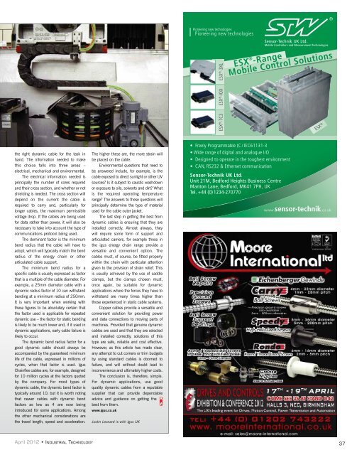
MACHINE BUILDING & AUTOMATIONPower & Data CablesA critical decision: cablesfor dynamic applicationsIn today’s sophisticated <strong>machine</strong>s, the need for moving power anddata supply is increasingly common. But, if safe and reliable operationis to be achieved, choosing the correct cable for these applications isa critical decision. Justin Leonard looks at the factors that must beconsidered and explains why standard cables are unsuitableIn a dynamic application – that is, anapplication where a cable is used toconnect moving parts of a <strong>machine</strong> –cables may have to move backwardsand forwards, in a rolling loop or even witha twisting motion. In today’s highperformance <strong>machine</strong>s, these movementstypically take place at high speed and it iscommon for them to be repeatedthousands or even millions of times in ashort timescale.Standard cables are totally unsuited tothis type of application. They have a verysimple construction where each of theircopper cores is made up of a small numberof relatively large conductor strands. Whencables of this type are subjected to repeatedbending at a small bend radius, the copperstrands making up each core ‘work harden’,become increasingly brittle and then break.The same process can easily bedemonstrated by bending an ordinary paperclip back and forth. Initially, it is flexible andbends easily, but after a short time it ‘workhardens’ and breaks. The breaking ofconductor cores because of work hardeningis a very common failure mode, usuallyleading to intermittent signals and data orshorting. There are other modes of failurewhen an unsuitable type of cable is used ina dynamic application.In multicore cables, the cores arealways twisted together in layers and instandard cables this twist has a long pitch.This means that when the cable bends, theinner cores are compressed while the outercores are stretched. After a time, thisprocess forces the cable to take up acorkscrew shape which, in effect, shortensit, and often pulls the cores out of theirterminations or connectors. The deformedcable may also form loops that get trappedin the carrier or in <strong>machine</strong> parts, damagingthe outer jacket and exposing the coreconductors.A third failure mode occurs when thecores untwist under the outer jacket of thecable, due to the forces described above. Ona standard cable, this outer jacket is a simpletubular extrusion. This is beneficial whenterminating the cable, because the jacketdoes not grip the cores tightly and is,therefore, easy to strip back. In dynamicapplications, however, the jacket has theimportant role of stopping the cores fromuntwisting, and even with dummy filler coresor strings (a common trick used to pack outthe inner construction on a standard cable) asimple tubular jacket is not effective in doingthis. The result is that the cores untwist withinthe jacket, and this can be seen as bulgesalong the length of the cable. Ultimately, theouter jacket will burst under the strain.With shielded cables, there’s yetanother problem. The braiding angle of theshield is usually steep, but this means thatthe braid has a tendency to open up andcreate gaps in the shielding when the cableis flexed; this leads to a worse quality ofEMC protection. Also because of the steepangle, the braid will be extended andcompressed under bending leading to workharden and fracture. This leaves sharp endsthat can pierce the insulation of the innercores leading to earth faults, or cut into theouter jacket starting a split.So much for the shortcomings ofstandard cables in dynamic applications, buthow do cables specifically designed for theapplications – ‘dynamic’ cables – overcomeThe dominant factor is theminimum bend radius thatthe cable with have toadopt, matching the bendradius of the energy chainthese problems? First of all, the copper coresare more finely stranded. However, it is acommon misconception that the finer thestrand the better; the strand size mustactually be optimised for maximum flexibilityThis type of construction reduces the risk ofwork hardening and core fractures, and canbe used to give even large core high-currentmotor cables the flexibility needed forreliable operation in dynamic applications.Next, in a dynamic cable, the cores aretwisted with a much shorter pitch and, inmulticore cables, the cores are braided andbundled wherever possible. This means thatthe path of the core takes it from the outsideof the cable to the inside and back again overa very short distance. Because this distance(Below) Standard cables are totally unsuited to dynamic applications(Left) Jacket ruptured due to broken shielding element(Above) General dynamic cable layup view (Top) Standard nondynamiccable layup (Above right) General <strong>machine</strong> with e-chainand Igus Chainflex cables installedis so short, the compression and tensionstresses experienced by the core, when thecable is flexed, cancel each other out to alarge extent, which means that the overalllevel of stress on the cores is greatly reduced.Dynamic cables still rely on the outerjacket to prevent the cores from untwisting,but instead of a plain extruded jacket, a gooddynamic cable will have a pressure-filledjacket. This fills all of the space around thecores (meaning dummy cores or strings arenot needed) and ensures that they cannotuntwist.In good quality dynamic cables whereEMC shielding is required, this will be of thebraided type rather than wound foil, and itwill have a shallow braid angle to preventgaps opening up as the cable flexes, whichwould reduce the effectiveness of theshielding. The shallow angle reduces stresson the strands, whose sizes will also havebeen chosen to maximise flexibility, whileminimising the risk of work hardening.Because of their special construction,dynamic cables often feel stiffer than theirstandard counterparts. This shows that themyth suggesting that the cables mostsuitable for dynamic applications are themost flexible is not only wrong but alsomisleading. A rough and ready test todetermine whether or not a cable is properlyconstructed for dynamic applications is tobend it tightly. A good dynamic cable willreturn immediately to its original shapewhen released, but other cables will tend toretain a kink.We have already seen why it is essentialto use dynamic cables in dynamicapplications if safety and reliability are to beassured, but it is also necessary to choose36INDUSTRIAL TECHNOLOGY • April 2012
ESX ® -3XLESX ® -RangeMobile Control SolutionsESX ® -TC3ESX ® -IOXESX ®the right dynamic cable for the task inhand. The information needed to makethis choice falls into three areas –electrical, mechanical and environmental.The electrical information needed isprincipally the number of cores requiredand their cross section, and whether or notshielding is needed. The cross section willdepend on the current the cable isrequired to carry and, particularly forlonger cables, the maximum permissiblevoltage drop. If the cables are being usedfor data rather than power, it will also benecessary to take into account the type ofcommunications protocol being used.The dominant factor is the minimumbend radius that the cable will have toadopt, which will typically match the bendradius of the energy chain or otherarticulated cable support.The minimum bend radius for aspecific cable is usually expressed as factorthat is a multiple of the cable diameter. Forexample, a 25mm diameter cable with adynamic radius factor of 10 can withstandbending at a minimum radius of 250mm.It is very important when working withthese figures to be absolutely certain thatthe factor used is applicable for repeateddynamic use – the factor for static bendingis likely to be much lower and, if it used indynamic applications, early cable failure islikely to occur.The dynamic bend radius factor for agood dynamic cable should always beaccompanied by the guaranteed minimumlife of the cable, expressed in millions ofcycles, when that factor is used. IgusChainflex cables are, for example, designedfor 10 million cycles at the factors quotedby the company. For most types ofdynamic cable, the dynamic bend factor istypically around 10, but it is worth notingthat newer cables with dynamic bendfactors as low as 4 are now beingintroduced for some applications. Amongthe other mechanical considerations arethe travel length, speed and acceleration.The higher these are, the more strain willbe placed on the cable.Environmental questions that need tobe answered include, for example, is thecable exposed to direct sunlight or other UVsources? Is it subject to caustic washdownor exposure to oils, solvents and dirt? Whatis the required operating temperaturerange? The answers to these questions willprincipally determine the type of materialused for the cable outer jacket.The last step in getting the best fromdynamic cables is ensuring that they areinstalled correctly. Almost always, theywill require some form of support andarticulated carriers, for example those inthe igus energy chain range provide aversatile and convenient option. Thecables must, of course, be fitted properlywithin the chain with particular attentiongiven to the provision of strain relief. Thisis usually achieved by the use of saddleclamps, but the clamps chosen must,once again, be suitable for dynamicapplications where the forces they have towithstand are many times higher thanthose experienced in static cable systems.Copper cables provide a versatile andconvenient solution for providing powerand data connections to moving parts of<strong>machine</strong>s. Provided that genuine dynamiccables are used and that they are selectedand installed correctly, solutions of thistype are safe, reliable and cost effective.However, as this article has made clear,any attempt to cut corners or trim budgetsby using standard cables is doomed tofailure, and will without doubt lead toinconvenience and ultimately higher costs.The conclusion is, therefore, simple.For dynamic applications, use goodquality dynamic cables from a reputablesupplier that can provide dependableadvice and guidance on getting thebest from them.www.igus.co.ukJustin Leonard is with Igus UK• Freely Programmable (C/ / IEC61131-3)• Wide range of digital and analogue I/O• Designed to operate in the toughest environments• CAN, RS232 & Ethernet communicationsSensor-Technik UK Ltd.Unit 21M, Bedford Heights Business CentreManton Lane, Bedford, MK41 7PH, UKTel. +44 (0) 1234-270770sensor-technikApril 2012 • INDUSTRIAL TECHNOLOGY37