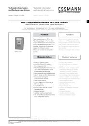
Technical information and operating instruction ... - Essmann
Technical information and operating instruction ... - Essmann
Technical information and operating instruction ... - Essmann

Create successful ePaper yourself
Turn your PDF publications into a flip-book with our unique Google optimized e-Paper software.
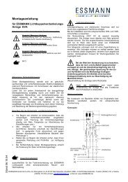
LeitungsverlegungRouting of cablesDruckgasgeneratorenPressurized gas generators 8. 3. 2. 1.letzter autom. Melder mit Endwiderst<strong>and</strong> (10 K Ohm, max. 10 Stück)last autom. detector with end resistor, max. 10 pieces autom. Melderautom. detector RWA-Bedienstelle, max. 10 StückSHE manual call point, max.10 piecesletzte RWA-Bedienstelle mit Endwiderst<strong>and</strong>, max. 10 Stücklast SHE manual call point, max. 10 piecesSteuerzentraleControl panelTabelle LeitungsquerschnittScheme of cable cross sectionNetz 230 V / 50 HzNYM-J 3 x 1,5 mm²,Netz 400 V / 50 HzNYM-J 5 x 1,5 mm²,separat abschaltbaren Stromkreis vorsehen.Vor unbeabsichtigtem Abschalten sichern.Mains 230 V / 50 HzNYM-J 3 x 1.5 mm²,Netz 400 V / 50 HzNYM-J 5 x 1,5 mm²,provide a separatelydisconnetible circuit.Secure against unintentinalswitching-off. Installationskabel NYM-J mit grün/gelbInstallation cable NYM-J with green/yellowAnzahl der DruckgasgeneratorenQuantity of pressurized gas generators maximale Länge (m)max. lengths (m)1) Es dürfen nur Druckgasgeneratoren mit einem garantierten Innenwiderst<strong>and</strong> von1,0 bis 1,6 Ohm pro Druckasgenerator zur Verwendung kommen.2) Die Klemmstellen in der Steuerzentrale sind für maximale Leitungsquerschnitte bis2,5 mm² ausgelegt. Werden größere Querschnitte verwendet, so ist eine Querschnittreduzierungunmittelbar vor der Steuerzentrale durchzuführen.1) Only pressurized gas generators with a guaranteed internal resistance of 1.0 to 1.6ohms per pressurized gas generator may be used.2) The terminals in the central control unit are designed for maximum wiring crosssectionsof 2.5 mm2. If larger cross-sections are used then the cross-section must bereduced in size immediately ahead of the central control unit.Es sind die gültigen Vorgaben bzgl. einer Verkabelungmit Funktionserhalt 30 Min. oder 90 Min. einzuhalten.Abweichungen hierzu sind in jedem Fall mit der Bauleitung, mit denörtlichen Abnahmebehörden, Energieversorgungsunternehmen,Br<strong>and</strong>schutzbehörden oder der Berufsgenossenschaftabzustimmen.Die angegebenen Leitungsquerschnitte dürfen nicht verringertwerden. Sie sind für eine Umgebungstemperatur von 20 °Cangegeben. Für höhere Temperaturen, die Querschnitte erhöhen.Bei E90 (E30) müssen die Leitungsquerschnitte entsprechend denVorschriften des Herstellers angepasst werden.Alle Leitungen zu der Steuerzentrale (außer Netzzuleitung) führen24 V DC und müssen getrennt von der Netzzuleitung verlegtwerden. Bei der Leitungsverlegung sind die entsprechenden VDE-Vorschriften zu beachten.Make sure all cable types <strong>and</strong> specifications areaccording to site management requirements <strong>and</strong> the appropriatenational <strong>and</strong> local codes <strong>and</strong> laws.The stated cable cross sections must not be reduced.They are listed for an ambient temperature of 20 °C. Increase thecross sections for higher temperatures.For E90 (E30), all cable cross sections must be adapted to themanufacturer‘s specifications.All cables to the control panel (except the mains supply lead) carry24 V DC <strong>and</strong> must be routed separately from the mains supplylead. When routing the cables, please observe the correspondingVDE regulations.11