Introduction to Robotics (CS223A) Homework #6 Solution (Winter ...
Introduction to Robotics (CS223A) Homework #6 Solution (Winter ...
Introduction to Robotics (CS223A) Homework #6 Solution (Winter ...
- No tags were found...
You also want an ePaper? Increase the reach of your titles
YUMPU automatically turns print PDFs into web optimized ePapers that Google loves.
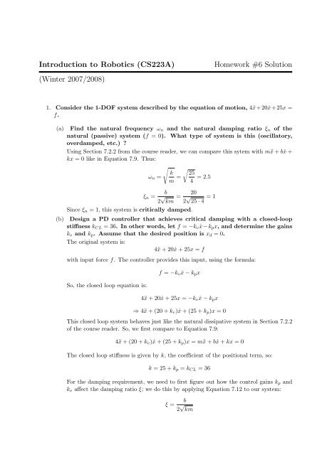
<strong>Introduction</strong> <strong>to</strong> <strong>Robotics</strong> (<strong>CS223A</strong>)<strong>Homework</strong> <strong>#6</strong> <strong>Solution</strong>(<strong>Winter</strong> 2007/2008)1. Consider the 1-DOF system described by the equation of motion, 4ẍ+20ẋ+25x =f.(a) Find the natural frequency ω n and the natural damping ratio ξ n of thenatural (passive) system (f = 0). What type of system is this (oscilla<strong>to</strong>ry,overdamped, etc.) ?Using Section 7.2.2 from the course reader, we can compare this sytem with mẍ + bẋ +kx = 0 like in Equation 7.9. Thus:√ √k 25ω n =m = 4 = 2.5(b)ξ n =b2 √ km = 202 √ 25 · 4 = 1Since ξ n = 1, this system is critically damped.Design a PD controller that achieves critical damping with a closed-loopstiffness k CL = 36. In other words, let f = −k v ẋ−k p x, and determine the gainsk v and k p . Assume that the desired position is x d = 0.The original system is:4ẍ + 20ẋ + 25x = fwith input force f. The controller provides this input, using the formula:So, the closed loop equation is:f = −k v ẋ − k p x4ẍ + 20ẋ + 25x = −k v ẋ − k p x⇒ 4ẍ + (20 + k v )ẋ + (25 + k p )x = 0This closed loop system behaves just like the natural dissipative system in Section 7.2.2of the course reader. So, we first compare <strong>to</strong> Equation 7.9:4ẍ + (20 + k v )ẋ + (25 + k p )x = mẍ + bẋ + kx = 0The closed loop stiffness is given by k, the coefficient of the positional term, so:k = 25 + k p = k CL = 36For the damping requirement, we need <strong>to</strong> first figure out how the control gains k p andk v affect the damping ratio ξ; we do this by applying Equation 7.12 <strong>to</strong> our system:ξ =b2 √ km
For critical damping:so the coefficient b of ẋ must satisfyξ = 1b = 2 √ km = 2 √ 36 · 4 = 24Based on our closed loop equation, we have:b = 20 + k vso the gains that we need areand the PD controller isk p = 11, k v = 4f = −4ẋ − 11x(c)Assume that the friction model changes from linear (20ẋ) <strong>to</strong> Coulomb friction,30sign(ẋ). Design a control system which uses a non-linear model-basedportion with trajec<strong>to</strong>ry following <strong>to</strong> critically damp the system at all timesand maintain a closed-loop stiffness of k CL = 36. In other words, let f = αf ′ +βand f ′ = ẍ d − k ′ v(ẋ − ẋ d ) − k ′ p(x − x d ). Then, find f,α,β,f ′ ,k ′ p and k ′ v. Note thatf is an m-mass control, and f ′ is a unit-mass control. Use the definition oferror, e = x − x d .The differential equation for the system is now4ẍ + 30sign(ẋ) + 25x = fIn order <strong>to</strong> linearize it, we apply a force f of the formwheref = αf ′ + βα = 4, β = 30sign(ẋ) + 25xFor purposes of control, this makes the system look like the unit-mass system:<strong>to</strong> which we apply the controlẍ = f ′f ′ = ẍ d − k ′ v(ẋ − ẋ d ) − k ′ p(x − x d )Substituting in<strong>to</strong> our unit-mass system yields the equationë + k ′ vė + k ′ pe = 0where e is the position error, e = x − x d .Now, we want <strong>to</strong> choose our gains k ′ p and k ′ v so that we achieve critical damping and thedesired closed-loop stiffness.To look at the closed loop stiffness, we need <strong>to</strong> consider the controlled system beforefac<strong>to</strong>ring out the mass:4ẍ + 30sign(ẋ) + 25x = αf ′ + β⇒ 4ẍ = αf ′
(d)⇒ 4ẍ + αf ′ = 0⇒ 4(ẍ − ẍ d ) + 4k ′ v(ẋ − ẋ d ) + 4k ′ p(x − x d ) = 0⇒ 4ë + 4k ′ vė + 4k ′ pe = 0The coefficient of the e term is the closed loop stiffness, so: k p ′ = 9.In order <strong>to</strong> have critical damping, we need <strong>to</strong> have ξ = 1. Using Equation 7.12 we seethat the coefficient of ė must be:√k v ′ = 2 k p ′ = 6Thus, the control isf = αf ′ + βα = 4β = 30sign(ẋ) + 25xf ′ = ẍ d − 6(ẋ − ẋ d ) − 9(x − x d )Given a disturbance force f dist = 4, what is the steady-state (ë = ė = 0) errorof the system in part (c)?We can analyze the error by observing the error in the unit-mass system. With adisturbance force added, the system’s equation of motion becomes4ẍ + 30sign(ẋ) + 25x = f + f distTo linearize the system, we apply a force of the same form as before:f + f dist = 4f ′ + 30sign(ẋ) + 25x + f dist(= 4 f ′ + f )dist+ 30sign(ẋ) + 25x4This yields a unit-mass system as before, but now it has a disturbance force of f dist /4,so the unit-mass system now looks likeẍ = f ′ + f dist4With the control from before, we get a unit-mass closed-loop system ofë + 6ė + 9e = f dist4For the steady state, when ẍ = ẋ = 0, we getSo, the steady state error is given by9e = f dist4e = f dist4 · 9 = 436 ≈ 0.1112. For a certain RR manipula<strong>to</strong>r, the equations of motion are given by[ ] [ ] [4 + c2 1 + c 2 ¨θ1 −s2 (+˙θ 2 2 + 2 ˙θ] [ ]1 ˙θ2 ) τ1=1 + c 2 1 ¨θ 2 s 2 ˙θ2 1τ 2
(a) Assume that joint 2 is locked at some value θ 2 using brakes and joint 1is controlled with a PD controller, τ 1 = −40 ˙θ 1 − 400(θ 1 − θ 1d ). What is theminimum and maximum inertia perceived at joint 1 as we vary θ 2 ? Whatare the corresponding closed-loop frequencies?For joint 2 locked (¨θ 2 = ˙θ 2 = 0), the equation of motion for joint 1 is:(4 + c 2 )¨θ 1 = τ 1The inertia seen at joint 1 is the coefficient of the ¨θ 1 term, (4 + c 2 ). So, this inertiaachieves its maximum and minimum values at θ 2 = 0 and θ 2 = 180 ◦ :The closed-loop equation for joint 1 ism max = 5, m min = 3(4 + c 2 )¨θ 1 + 40 ˙θ 1 + 400(θ 1 − θ 1d ) = 0To get an expression for closed loop frequency, we compare our closed loop equationwith the generic system of Equation 7.9 (mẍ + bẋ + kx = 0).The closed loop frequency is then given by:So, we have√ √k 400ω =m = (4 + c 2 )m = m max ⇒ ω min = √ 205m = m min ⇒ ω max = √ 203(b)Still assuming that joint 2 is locked, at what values of θ 2 do the minimumand maximum damping ratios occur? What are the minimum and maximumdamping ratios?To get an expression for damping ratio, we once again compare our closed loop equationwith the generic system of Equation 7.9 (mẍ+bẋ+kx = 0). In this case, using Equation7.12 the closed-loop damping ratio is given by:ξ =b2 √ km = 402 √ 400m = √ 1 = m1√ 4 + c2So, the minimum and maximum values of ξ occur at θ 2 = 0 and θ 2 = 180 ◦ :ξ min =ξ max =1√ = √ 1mmax 51√ = √ 1mmin 3(c)Now assume that both joints are free <strong>to</strong> move, and that this system iscontrolled by a partitioned PD controller, τ = ατ ′ + β. Design a partitioned,trajec<strong>to</strong>ry-following controller (one that tracks a desired position, velocityand acceleration) which will provide a closed-loop frequency of 10 rad/sec
on joint 1 and 20 rad/sec on joint 2 and be critically damped over the entireworkspace. That is, letτ ′ = ¨θ d −[ ]k′v100 k v ′ ( ˙θ − ˙θ d ) −2[ ]k′p100 k p ′ (θ − θ d ),2then find the matrices α and β and the vec<strong>to</strong>r τ, along with the necessarygains k ′ v iand k ′ p i.The equations of motion are of the formM(θ)¨θ + V ( ˙θ, θ) = τ<strong>to</strong> which we apply a vec<strong>to</strong>r of <strong>to</strong>rques τ of the formτ = ατ ′ + βTo make this look like a unit-mass system, we letα = M(θ), β = V ( ˙θ, θ)which gives the unit-mass system¨θ = τ′To this system, we apply the controlτ ′ = ¨θ d −This yields two closed-loop equations[ ]k′v100 k v ′ ( ˙θ − ˙θ d ) −2ë 1 + k ′ v 1 ė 1 + k ′ p 1e 1 = 0ë 2 + k ′ v 2 ė 2 + k ′ p 2e 2 = 0[ ]k′p100 k p ′ (θ − θ d ),2where e i is the error at joint i, e i = (θ i − θ id ). Now, we need <strong>to</strong> choose k v ′ iand k p ′ i<strong>to</strong> achieve critical damping, and <strong>to</strong> achieve our desired closed-loop frequencies. For aunit-mass system, we choosek ′ p i= ω 2 ik ′ v i= 2ξ i ω iSo, we getk ′ p 1= 100, k ′ v 1= 20k ′ p 2= 400, k ′ v 2= 40(d)If θ 2 = 180 ◦ , what is the steady-state error vec<strong>to</strong>r for a given disturbance<strong>to</strong>rque, τ dist = [2 4] T ?The controlled system, with a disturbance <strong>to</strong>rque τ dist isM(θ)¨θ + V ( ˙θ, θ) = τ + τ distSubstituting in our form for τ = ατ ′ + β yieldsM(θ)¨θ − M(θ)τ ′ = τ dist


