Application of Seamless Simulation of Seismic Response Analysis ...
Application of Seamless Simulation of Seismic Response Analysis ...
Application of Seamless Simulation of Seismic Response Analysis ...
- No tags were found...

You also want an ePaper? Increase the reach of your titles
YUMPU automatically turns print PDFs into web optimized ePapers that Google loves.
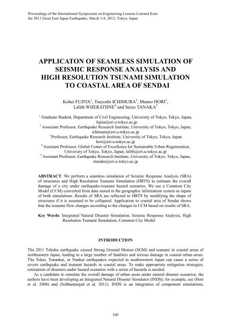
Proceedings <strong>of</strong> the International Symposium on Engineering Lessons Learned fromthe 2011 Great East Japan Earthquake, March 1-4, 2012, Tokyo, JapanAPPLICATON OF SEAMLESS SIMULATION OFSEISMIC RESPONSE ANALYSIS ANDHIGH RESOLUTION TSUNAMI SIMULATIONTO COASTAL AREA OF SENDAIKohei FUJITA 1 , Tsuyoshi ICHIMURA 2 , Muneo HORI 3 ,Lalith WIJERATHNE 4 and Seizo TANAKA 51 Graduate Student, Department <strong>of</strong> Civil Engineering, University <strong>of</strong> Tokyo, Tokyo, Japan,fujita@eri.u-tokyo.ac.jp2 Associate Pr<strong>of</strong>essor, Earthquake Research Institute, University <strong>of</strong> Tokyo, Tokyo, Japan,ichimura@eri.u-tokyo.ac.jp3Pr<strong>of</strong>essor, Earthquake Research Institute, University <strong>of</strong> Tokyo, Tokyo, Japanhori@eri.u-tokyo.ac.jp4 Assistant Pr<strong>of</strong>essor, Global Center <strong>of</strong> Excellence for Sustainable Urban Regeneration,University <strong>of</strong> Tokyo, Tokyo, Japan, lalith@eri.u-tokyo.ac.jp5 Assistant Pr<strong>of</strong>essor, Earthquake Research Institute, University <strong>of</strong> Tokyo, Tokyo, Japan,stanaka@eri.u-tokyo.ac.jpABSTRACT: We perform a seamless simulation <strong>of</strong> <strong>Seismic</strong> <strong>Response</strong> <strong>Analysis</strong> (SRA)<strong>of</strong> structures and High Resolution Tsunami <strong>Simulation</strong> (HRTS) to estimate the overalldamage <strong>of</strong> a city under earthquake-tsunami hazard scenarios. We use a Common CityModel (CCM) converted from data stored in the geographic information system as inputs<strong>of</strong> both simulations. Results <strong>of</strong> SRA are reflected to HRTS by modifying the shape <strong>of</strong>structures if it is assumed to be collapsed. <strong>Application</strong> to coastal area <strong>of</strong> Sendai showsthat the tsunami flow changes according to the changes in CCM based on results <strong>of</strong> SRA.Key Words: Integrated Natural Disaster <strong>Simulation</strong>, <strong>Seismic</strong> <strong>Response</strong> <strong>Analysis</strong>, HighResolution Tsunami <strong>Simulation</strong>, Common City ModelINTRODUCTIONThe 2011 Tohoku earthquake caused Strong Ground Motion (SGM) and tsunami in coastal areas <strong>of</strong>northeastern Japan, leading to a large number <strong>of</strong> fatalities and serious damage in coastal urban areas.The Tokai, Tonankai, or Nankai earthquakes expected in southwestern Japan can cause a series <strong>of</strong>severe earthquake and tsunami hazards in coastal areas. To make appropriate mitigation strategies,estimation <strong>of</strong> disasters under hazard scenarios with a series <strong>of</strong> hazards is needed.As a candidate to simulate the overall damage <strong>of</strong> urban areas under natural disaster scenarios, theauthors have been developing an Integrated Natural Disaster Simulator (INDS); for example, see (Horiet al. 2008) and (Sobhaninejad et al. 2011). INDS is an integration <strong>of</strong> component simulations,540
simulating each phase <strong>of</strong> an urban disaster. Each component simulation uses physics-basedcomputational methods with input city models that reflect the actual properties <strong>of</strong> a city, constructedfrom data stored in the Geographic Information System (GIS). In the past, the main development <strong>of</strong>INDS was targeted on earthquake disasters (Integrated Earthquake Simulator, IES). IES integratesseismic wave propagation analysis from the fault to city, <strong>Seismic</strong> <strong>Response</strong> <strong>Analysis</strong> (SRA) <strong>of</strong>structures using the computed SGM, and simulation <strong>of</strong> evacuation processes using Multi Agent<strong>Simulation</strong>.In this paper, we integrate SRA and High Resolution Tsunami <strong>Simulation</strong> (HRTS). We aim tosimulate damage and collapse <strong>of</strong> structures, since it is essential to ensure human life space. For SRA,we use non-linear structural analysis methods on each structure in the target area. For tsunamisimulation, we use HRTS, which is a tsunami simulation using a three-dimensional analysis methodaimed to analyze destruction <strong>of</strong> structures and collapse <strong>of</strong> structures due to tsunami loading. Sincesuch a tsunami analysis code is unavailable to the authors, we develop a code using standardcomputational fluid analysis methods and distributed memory type parallelization methods.We perform a seamless simulation <strong>of</strong> SRA and HRTS by exchanging information betweensimulations. We exchange information via Common City Model (CCM), which is a common data set<strong>of</strong> spatial and temporal properties <strong>of</strong> a city, accessible from each component simulation. Here, wedevelop data conversion modules that convert data stored in GIS to CCM, and data conversionmodules that exchange information between component simulations and CCM.As an application <strong>of</strong> the developed method, we conduct a simulation targeted on the coastal area <strong>of</strong>Sendai. We convert external shapes <strong>of</strong> structures and ground elevation data stored in GIS to CCM, andmake input structure dataset for SRA. We assume a criterion for a structure to collapse, and modify thestructural shapes in CCM based on the results <strong>of</strong> SRA. We compare the results <strong>of</strong> HRTS run on themodified and original city configuration to confirm that we can run a seamless simulation that couldbe used to evaluate the overall damage <strong>of</strong> a city under a series <strong>of</strong> earthquake and tsunami hazards.METHODOLOGYIn this section, we explain about the framework developed to perform a seamless simulation <strong>of</strong> SRAand HRTS. In order to make an extendible method to accommodate multiple GIS data and componentsimulations, we use CCM. CCM is a common data set that stores the properties <strong>of</strong> a city in commondata format. We first convert data stored in GIS to CCM. Then, each component simulation readsrelevant parts <strong>of</strong> CCM and makes an input city model, analyzes and writes the modifications to thecity model back to CCM; see Fig.1. By using a common data set <strong>of</strong> a city, we can integrate simulationswithout the hassle to make direct data conversion modules between each component simulation. Thefollowing are the details <strong>of</strong> the conversion methods and analysis methods used in this paper.We convert elevation and structure data stored in GIS to CCM. Here, we develop modules thatconvert Digital Elevation Map (DEM) and two-dimensional vector structure data to CCM; see arrow(i) and (ii) in Fig. 1.GIS datacomponentsimulationsDEM2D vectordata(i)(ii)CCM(iii)(v)(iv)SRAHRTSFig. 1 Design <strong>of</strong> INDS using CCM541
38°30’NatoriSendaiArahama38°15’38°00’140°45’ 141°00’ 141°15’Fig. 2 Target area. Arahama, Wakabayashi ward, Sendai city, Japan.The inputs <strong>of</strong> SRA are the shape <strong>of</strong> structures and input SGM. We convert structure shape data inCCM to inputs <strong>of</strong> SRA; see arrow (iii) in Fig.1. Since properties <strong>of</strong> structural members are notavailable in GIS, we guess the material properties and configuration <strong>of</strong> structural members using theexternal shape <strong>of</strong> structures based on the design code <strong>of</strong> Japan. SRA is performed using apre-developed code using One Component Model (OCM). OCM is a non-linear structural analysismethod designed for analysis <strong>of</strong> RC structures. The output <strong>of</strong> SRA is the time series <strong>of</strong> displacement <strong>of</strong>structures. We assume a criterion for a structure to collapse and change the CCM according to SRAresults; see arrow (iv) in Fig.1. For simplicity, we assume that a structure will collapse if the maximumdrift angleR = max|u|/h, (1)is larger than a threshold R 0 . Here, max|u| is the maximum displacement during the simulation and h isthe height <strong>of</strong> a structure. We modify the shape <strong>of</strong> a structure by making the height 1/4 and spreadingthe structure 1.5 times in the horizontal directions if a structure is determined to be collapsed.The inputs <strong>of</strong> HRTS are the external shapes <strong>of</strong> structures and ground elevation, and input tsunamiwave. We convert the structure and ground elevation data in CCM for HRTS; see arrow (v) in Fig.1.We use a distributed memory type parallel analysis program using Smoothed Particle Hydrodynamics(SPH) for fluid analysis; see (Monaghan 1994) for details <strong>of</strong> SPH. The output <strong>of</strong> HRTS is a time series<strong>of</strong> fluid position, velocity and pressure. We do not change the configuration <strong>of</strong> the city based on HRTS,although we plan to do this in the future using a fluid-structure interaction method.APPLICATION TO COASTAL AREA OF SENDAI CITYWe apply the developed method to Arahama, Wakabayashi ward, Sendai, Japan, which is one <strong>of</strong> theseverely hit areas by the tsunami in the 2011 Tohoku earthquake; see Fig. 2. The objectives <strong>of</strong> thissection is to check that a seamless simulation <strong>of</strong> SRA and HRTS can be run on GIS datasets forestimation <strong>of</strong> overall damage in coastal areas under earthquake-tsunami disasters.We first convert data stored in GIS to CCM. The target area is a 2.0 x 3.0km domain with 1416structures. CCM consists <strong>of</strong> ground elevation and external shapes <strong>of</strong> structures; see Fig. 3. Here, GISdata provided by the Geospatial Information Authority <strong>of</strong> Japan and NTT Geospace Corporation isused as an input.We make an input city model for SRA and excite structures using SGM observed at K-NETMYG013 station (Sendai) in the 2011 <strong>of</strong>f the Pacific coast <strong>of</strong> Tohoku earthquake. For simplicity, we542
Fig. 3 Constructed CCM, consisting <strong>of</strong> external shape <strong>of</strong> structures and ground elevation. GIS dataprovided by Geospatial Information Authority <strong>of</strong> Japan and NTT Geospace Corporation is used.Fig. 4 Results <strong>of</strong> SRA at t = 91.0s from start <strong>of</strong> simulation. Colors indicate magnitude <strong>of</strong> deformation.<strong>Response</strong> <strong>of</strong> each structure under SGM observed in the 2011 Tohoku region earthquake is analyzed.input the same SGM to the base <strong>of</strong> each structure. The simulation is 0.01s x 30,000steps = 300s. Fig. 4shows snapshots at t = 91.0s after start <strong>of</strong> the simulation. From this figure we can see that structureshave different response to the same input SGM according to its height, shape, and directions.We deform structures by assuming that a structure will collapse if the maximum deformation angledefined in Eq. (1) is larger than a threshold R 0 = 1/40. We set this threshold relatively small comparedto the real estimate for a structure to collapse so that a number <strong>of</strong> structures will collapse; we do this tohave a clear difference between the modified and original city models. Fig. 5 shows the deformed state<strong>of</strong> the city, where blue indicates collapsed shape, transparent indicates original shape, and solid whiteindicate shapes <strong>of</strong> structures that are not determined to be collapsed.Two cases <strong>of</strong> HRTS are performed; case 1 is with the modification <strong>of</strong> structures based on SRA,and case 2 is the original CCM without modifications. We conduct HRTS on a 1,000 x 800m area,each discretized in resolution <strong>of</strong> 1m. We input tsunami wave using a block <strong>of</strong> water 12m in height withinitial velocity <strong>of</strong> 5m/s; see Fig. 6. Although this setting is quite different from the actual tsunami wavethat hit this area, it is enough to confirm that the HRTS is applicable to a real city dataset stored in GIS.We plan to use computed tsunami waves from the source to bay area as input tsunami waves in thefuture. The number <strong>of</strong> boundary particles used to model elevation and structure shapes for the 2 cases543
Fig. 5 Modified city model based on results <strong>of</strong> SRA. Blue indicate shape <strong>of</strong> structures that aredetermined to be collapsed, transparent shape indicate original shape, and solid white indicate shapes<strong>of</strong> structures that are not determined to be collapsed.Fig. 6 <strong>Simulation</strong> setting <strong>of</strong> HRTS. Domain size <strong>of</strong> 1000 x 800m is discretized in resolution <strong>of</strong> 1m, andinput tsunami wave (12m in height, initial velocity 5m/s), indicated in blue, is inputted from the coast.are 2,120,399 and 2,218,985, respectively, while the number <strong>of</strong> fluid particles used to model thetsunami is 3,694,981 for both <strong>of</strong> the cases. The simulation is 0.001s x 40,000steps = 40s. Figs. 7 and 8show the results for the two cases. From these figures, we can see that three dimensional flows aroundstructures are computed. Comparing these figures, we can see that flow changes according to themodification to the city configuration.CLOSING REMARKSIn this paper, we developed a framework to integrate SRA and HRTS by using CCM. We converteddata stored in the GIS to both the inputs for SRA and HRTS via CCM, and modified the cityconfiguration based on the results <strong>of</strong> SRA. HRTS is conducted using the modified city model.<strong>Application</strong> to coastal area <strong>of</strong> Sendai shows that the flow <strong>of</strong> tsunami changes according to themodification in the CCM based on results <strong>of</strong> SRA. Our future works are to develop fluid-structureinteraction methods to simulate destruction <strong>of</strong> structures under tsunami loading.544
Fig. 7 Results <strong>of</strong> HRTS for case 1 (with modification to city model based on SRA results). Colorsindicate fluid velocity. Left figure: t = 15s, Right figure t = 25s.Fig. 8 Results <strong>of</strong> HRTS for case 2 (original city model). Colors indicate fluid velocity.Left figure: t = 15s, Right figure t = 25s.ACKNOWLEDGMENTSThe authors would like to thank Dr. Toshikazu Kabeyasawa <strong>of</strong> Building Research Institute forproviding One-Component-Model structural analysis code used in this study. GIS data used in thisstudy was provided by the Geospatial Information Authority <strong>of</strong> Japan and NTT Geospace Corporation.We used K-NET SGM records provided by National Research Institute for Earth Science and DisasterPrevention (NIED) in this study.REFERENCESHori, M. and Ichimura, T. (2008). “Current state <strong>of</strong> integrated earthquake simulation for earthquakehazard and disaster.” Journal <strong>of</strong> Seismology, Vol. 12, 307-321.Monaghan, J. J. (1994). “Simulating free surface flows with SPH.” Journal <strong>of</strong> Computational Physics,Vol. 110, 309-406.Sobhaninejad, G., Hori, M., Kabeyasawa, T. (2011). “Enhancing integrated earthquake simulation withhigh performance computing.” Advances in Engineering S<strong>of</strong>tware, Vol. 42, No. 5, 286-292.545