Modular devices
Modular devices
Modular devices
- No tags were found...

Create successful ePaper yourself
Turn your PDF publications into a flip-book with our unique Google optimized e-Paper software.
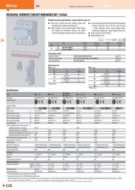
MiniaOFIResidual current circuit breakersRESIDUAL CURRENT CIRCUIT BREAKERS OFI (10 kA)Residual current circuit breakers, 4-pole, selective, type A-SThey react to both sine-wave residual current andpulsating direct residual current (type A).Special residual current circuit breakers which reducethe number of undesirable releases and enableselective switching of residual current circuit breakers.It is recommended to install them before the equipmentcausing short-time (up to 40 ms) stray currents– heavy induction motors, large heating bodies,interference suppressors, surge voltage arresters etc.Surge resistance: 5 kA (8/20 μs).Release delay: 40 ms.10 000I ΔnI nType Product Number Weight Package[mA] [A] code of modules [kg] [pcs]30040 OFI-40-4-300A-S 35297 4 0.52 163 OFI-63-4-300A-S 35298 4 0.52 1-25SSpecificationsAccessories to OFIAuxiliary switches PS-OF-1100, PS-OF125-1100 page C22Interconnecting busbars G2L-1000-16, G4L-1000-16, S4L-1000-16 page E52Terminal extensions AS-25-G, AS-25-S page E57Powers losses POFI-...-2-...I nI ΔnP 1)OFI-...-4-...I nI ΔnP 1)[A][A][W/pole][A][A][W/pole]16 0.01 2.50.03; 0.1 1.2250.03; 0.1 2 0.3 0.65250.30 10.03; 0.1 3.2400.03; 0.1 4 0.3; 0.5 1.65400.30 2.50.03; 0.1 41) 63Mean values 0.3; 0.5 3.280 0.3 4.81)Mean valuesType OFI-..-2-.. OFI-..-4-..OFI-100-4-..OFI-125-4-..OFI-..-2-..-G OFI-..-4-..-G OFI-..-4-..-SStandards EN 61008, IEC 755 EN 61008, IEC 755 EN 61008, IEC 755 EN 61008, IEC 755 EN 61008, IEC 755 EN 61008, IEC 755Approval marksNumber of poles 2 4 4 2 4 4Type AC, A AC, A AC, A AC-G, A-G G AC- G, A-G G A- S SRated curren I n16, 25, 40 A 25, 40, 63, 80 A 100, 125 A 25, 40 A 25, 40, 63 A 40, 63 ARated residual current I Δn10, 30, 100, 300 mA 10, 30, 100, 300, 500 mA 30, 100, 300, 500 mA 30 mA 30, 100 mA 300 mARated operating voltage U e230 V a.c. 230/400 V a.c. 230/400 V a.c. 230 V a.c. 230/400 V a.c. 230/400 V a.c.Min. operating voltage 1) U min100 V a.c. 100 V a.c. 100 V a.c. 100 V a.c. 100 V a.c. 100 V a.c.Max. operating voltage U max240 V a.c. 240/415 V a.c. 240/415 V a.c. 240 V a.c. 240/415 V a.c. 240/415 V a.c.Rated frequency f n50/60 Hz 50/60 Hz 50/60 Hz 50/60 Hz 50/60 Hz 50/60 HzRated conditional short-circuit current: I ncwith back-up fuse I n ≤ 63 A gG 10 kA - - 10 kA - -with back-up fuse I n ≤ 100 A gG - 10 kA 10 kA - 10 kA 10 kAwith back-up MCB LPN, LST with I n max. 1:1 10 kA 10 kA 10 kA 10 kA 10 kA 10 kAwith back-up MCB LPE with I n max. 1:1 6 kA 6 kA 6 kA 6 kA 6 kA 6 kARated making and breaking capacity I m500 A 800 A 1 250 A 500 A 800 A 800 ASurge resistance (8/20 μs) 1 kA 1 kA 1 kA 3 kA 3 kA 5 kARelease delay - - - 10 ms 10 ms 40 msMechanical endurance >10 000 operating cycles >10 000 operating cycles >10 000 operating cycles >10 000 operating cycles >10 000 operating cycles >10 000 operating cyclesElectrical endurance >10 000 operating cycles >10 000 operating cycles >10 000 operating cycles >10 000 operating cycles >10 000operating cycles >10 000 operating cyclesDegree of protection IP20 IP20 IP20 IP20 IP20 IP20ConnectionConductor 1 ÷ 16 mm 2 1.5 ÷ 25 mm 2 2.5 ÷ 50 mm 2 1 ÷ 16 mm 2 1.5 ÷ 25 mm 2 1.5 ÷ 25 mm 2Torque 2.5 Nm 3 Nm 3.5 Nm 3 Nm 3 Nm 3 NmTop or bottom connection yes yes yes yes yes yesOperating conditionsAmbient temperature type AC -5 ÷ 45 °C -5 ÷ 45 °C -5 ÷ 45 °C -25 ÷ 45 °C -25 ÷ 45 °C -25 ÷ 45 °Ctype A -25 ÷ 45 °C -25 ÷ 45 °C -25 ÷ 45 °C -25 ÷ 45 °C -25 ÷ 45 °C -25 ÷ 45 °CWorking position arbitrary arbitrary arbitrary arbitrary arbitrary arbitrarySeismic resistance IEC 980:1993 2) IEC 980:1993 2) - IEC 980:1993 2) IEC 980:1993 2) IEC 980:1993 2)1)For preserving the function of the test push-button2)It passed the seismic tests for NPP Dukovany and Temelín3)Rated conditional short-circuit current is related to short-circuit protection. It is also possible to protect residual current circuit breakers against overload by circuit breaker and fuse-link. In this case I nof MCBhas to be equal or lower than I nof RCCB (I n MCB ≤ I n RCCB ) and I nof fuse-link has to be by one degree lower than I nof RCCB (I ≤ I n of fuse-link by one degree lower n RCCB)C20