Modular devices
Modular devices
Modular devices
- No tags were found...

You also want an ePaper? Increase the reach of your titles
YUMPU automatically turns print PDFs into web optimized ePapers that Google loves.
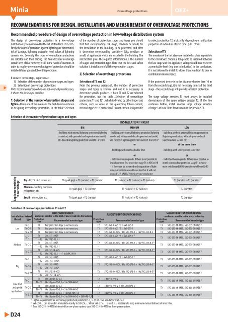
MiniaOvervoltage protectionsRECOMMENDATIONS FOR DESIGN, INSTALLATION AND MEASUREMENT OF OVERVOLTAGE PROTECTIONSRecommended procedure of design of overvoltage protection in low-voltage distribution systemThe design of overvoltage protection in a low-voltagedistribution system is solved by the set of standards EN 62305.Firstly the zones of protection against lightning are determined,risk of damage, lightning protection level, values of lightningcurrents etc. Secondly the types of overvoltage protectionsare selected and their placing. The final decision to undergocertain level of risk, however, is still in the hands of investors. Inorder to roughly determine what type of protection should beinstalled if any, you can follow this procedure.It consists in two steps, in particular:1) Selection of the number of protection stages and types2) Selection of overvoltage protectionsNote: recommended procedure can not cover all possible cases,it shows the basic logic to follow.1) Selection of the number of protection stages andtypes – this is one of the main and the first decisive criterionin designing overvoltage protection. In the table SelectionSelection of the number of protection stages and typesof the number of protection stages and types you shouldfirst find corresponding risk (high, medium or small) forthe installation in the building, to be protected, and afterit determine corresponding sensitivity (big, medium orsmall) of appliances which are installed in the building. Theintersection gives the required information i.e. the numberof stages and protection type. Note that the best and safestsolution is installation of all three protection stages.2) Selection of overvoltage protectionsSelection of T1 and T2From the previous paragraph, the number of protectionstages and types is known, and not it is necessary todetermine specific products. If both T1 and T2 are selectedfor protection, use the table „Selection of overvoltageprotections T1 and T2“ , which is divided by other importantcriteria, such as value of the quenching follow-current,network type etc. If protection T1 is not chosen, it is possibleto select protection T2 arbitrarily, depending on utilizationproperties of individual offered types (SVC, SVM).Selection of T3The arresters of the last stage are installed as close as possibleto the end device. Should a long cable be installed betweenthe last stage and the appliance, voltage could have rise overa permissible level (e.g. due to induction) in the conductors.It is not allowed to install T3 closer than 5 m from T2 due tocoordination maintenance.If the protected device is in the distance shorter than 10 mfrom the second stage, it is not necessary to install the thirdstage - the second stage will provide sufficient protection.The surge voltage arresters T3 must always be installeddownstream of the surge voltage arrester T2. If the linecontinues farther, install another surge voltage arrestersof stage 3 at least 10 m downstream of the previous T3.INSTALLATION THREATBIG MEDIUM LOW- buildings with external lightning protection (lightningconductor), with grounded roof superstructure (aerial)etc. classed in lightning protection level LPL I or LPL II- buildings with external lightning protection (lightningconductor), with grounded roof superstructure (aerial)etc. classed in lightning protection level LPL III or LPL IVor- buildings without external lightning protection(lightning conductor), without grounded roofsuperstructure (aerial) etc.at the same time- buildings with overhead cable lines - buildings with underground cable linesoror- Individual housing units, if there is not possible to - Individual housing units, if there is not possible toinstall common first protection stage T1 in HDS or HR install common first protection stage T1 in house- if there can be assumed such separation of lightningcurrent into several branches that it will notmain switchboard (HDS) or main switchboard (HR)exceed 12.5 kA(10/350 us) per one conductorAppliance sensitivityto overvoltageBig - PC, TV, Hi-Fi system etc. T1 (spark gap) + T2 (varistor) + T3 (varistor) T1 (varistor) + T2 (varistor) + T3 (varistor) T2 (varistor) + T3 (varistor)Medium - washing machines,refrigerators etc.T1 (spark gap) + T2 (varistor) T1 (varistor) + T2 (varistor) T2 (varistor)Small - motors, fans etc. T1 (spark gap) +T 2 (varistor) T1 (varistor) + T2 (varistor) T2 (varistor)Selection of overvoltage protections T1 and T2MAIN SWITCHBOARDSUBDISTRIBUTION SWITCHBOARDInstallation Network - as close as possible to the inlet of power lead into the buildingSUBDISTRIBUTION SWITCHBOARD- as close as possible to the protected devicethreat type Protectiontype Recommended arrester type Protectiontype Recommended arrester type ProtectiontypeRecommended arrester typeTN-C T1 first protection stage is not necessary T2 SVC-350-3-MZS / 3 ks SVC-275-1 T3 SVD-253-1N-MZS / SVD-335-3N-MZS 3)Low TN-C-S T1 first protection stage is not necessary T2 SVC-350-3-MZS / 3 ks SVC-275-1 T3 SVD-253-1N-MZS / SVD-335-3N-MZS 3)TN-S, TT T1 first protection stage is not necessary T2 SVC-350-3N-MZS / 3 ks SVC-275-1 + 1 ks SVC-255-N-S T3 SVD-253-1N-MZS / SVD-335-3N-MZS 3)T1 SJB-25E-3-MZS T2 SVC-350-3-MZS / 3 ks SVC-275-1TN-CT1 + T2 3 ks SVBC-12,5-1 -T3 SVD-253-1N-MZS / SVD-335-3N-MZS 3)T1 SJB-25E-3-MZS T2 SVC-350-3N-MZS / 3 ks SVC-275-1 + 1 ks SVC-255-N-SMedium TN-C-ST1 + T2 3 ks SVBC-12,5-1 -T3 SVD-253-1N-MZS / SVD-335-3N-MZS 3)T1 SJB-25E-3N-MZS T2 SVC-350-3N-MZS / 3 ks SVC-275-1 + 1 ks SVC-255-N-STN-S, TTT1 + T2 3 ks SVBC-12,5-1 + 1 ks SVBC-50-N -T3 SVD-253-1N-MZS / SVD-335-3N-MZS 3)T1 SJB-25E-3-MZS T2 SVC-350-3-MZS / 3 ks SVC-275-1TN-CT1 + T2 SJBC-25E-3-MZS -T3 SVD-253-1N-MZS / SVD-335-3N-MZS 3)T1 SJB-25E-3-MZS T2 SVC-350-3N-MZS / 3 ks SVC-275-1 + 1 ks SVC-255-N-SBig TN-C-ST1 + T2 SJBC-25E-3-MZS -T3 SVD-253-1N-MZS / SVD-335-3N-MZS 3)T1 SJB-25E-3N-MZS T2 SVC-350-3N-MZS / 3 ks SVC-275-1 + 1 ks SVC-255-N-STN-S, TTT1 + T2 SJBC-25E-3N-MZS -T3 SVD-253-1N-MZS / SVD-335-3N-MZS 3)T1 3 ks SJBplus-50-2,5 T2 3 ks SVM-440-ZTN-CT3 SVD-253-1N-MZS / SVD-335-3N-MZST1+T2 3 ks SJBplus-50-2,5 + 3 ks SVM-440-Z -3)IndustrialT1 3 ks SJBplus-50-2,5 T2 3 ks SVM-440-Z + 1 ks SVM-NPE-Zand special TN-C-ST3 SVD-253-1N-MZS / SVD-335-3N-MZST1+T2 3 ks SJBplus-50-2,5 + 3 ks SVM-440-Z -3)applications 1)T1 3 ks SJBplus-50-2,5 + 1 ks SJB-NPE-1,5 T2 3 ks SVM-440-Z + 1 ks SVM-NPE-ZTN-S, TTT3 SVD-253-1N-MZS / SVD-335-3N-MZST1+T2 3 ks SJBplus-50-2,5 + 3 ks SVM-440-Z + SJB-NPE-1,5 -3)1)Higher requirements for overvoltage protection parameters (I fi> 25 kA, two-conductor lead etc.)2)SVC-350-... Can be used in immediate vicinity to SJB-25E-... When SVC-275-…is used, it is necessary to keep minimum mutual distance of lines 10 m.3)Type SVD-253-1N-MZS is intended for one-phase system, type SVD-335-3N-MZS for three-phase system.D24