Modular devices
Modular devices
Modular devices
- No tags were found...

Create successful ePaper yourself
Turn your PDF publications into a flip-book with our unique Google optimized e-Paper software.
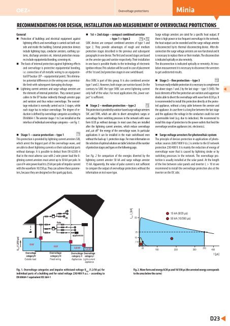
Overvoltage protectionsMiniaRECOMMENDATIONS FOR DESIGN, INSTALLATION AND MEASUREMENT OF OVERVOLTAGE PROTECTIONSGeneralProtection of buildings and electrical equipment againstlightning effects and overvoltage is carried out both outsideand inside the building. Еxternal protection <strong>devices</strong>include lightning traps, conductor arresters, earthing systems,discharge arresters etc. internal protection measuresinclude equipotential bonding, screening etc.The basis of internal protection against lightning effectsand overvoltage is protective equipotential bonding,i.e. connection of all metallic wiring to an equipotentialEP busbar (EP – equipotential point). This eliminatespotential differences in the wiring over a permissiblelimit with subsequent damaging discharge.Lightning current arresters and surge voltage arresters arethe elements of internal protection. They connect powercables to the EP busbar indirectly through arrester gapsand varistors and thus reduce overvoltage. The overvoltagereduction is normally carried out in 3 stages, whileeach stage has to reduce overvoltage. The degree of reductionis defined by overvoltage categories according toEN 60664-1. The arrester stages 1 to 3 are installed on theinterface of individual overvoltage categories – see Fig. 1.Stage 1 – coarse protection – type 1This protection is provided by lightning current arresters SJB,which arrest the biggest part of the overvoltage wave, andare able to divert lightning currents or their substantial partswithout damage. It is possible to deduct from EN 62305-4that in the most adverse case with 2-wire power lead the lightningcurrent arresters must arrest up to 50 kA per pole. Incase of 4-wire power lead it is 25 kA per pole of impulse currentwith the waveform 10/350 μs. They can achieve these parameters,because they are designed on the spark gap basis.1st + 2nd stage – compact combined arrester– type 1 + type 2 +SJBC <strong>devices</strong> are compact combined arresters of type 1 andtype 2. They provide advantages of rough and mediumprotection stages described in the previous and subsequentparagraphs in one device. The first and second stages are basedon the arrester gap and varistor respectively. Their installationin one base is possible thanks to the technology of electronicignition release.This solution will be used in case of placementof the 1st and 2nd protection stages in one switchboard.Also SVBC is part of this group. It is also combined arrestertype 1 and 2. However, both stages are varistor based. On thecontrary to SJBC the type SVBC can arrest lightning currentonly half of the value. For most applications this „lower output“is sufficient.Stage 2 – medium protection – type 2This protection is provided by varistor-based surge voltage arrestersSVC and SVM, which are able to divert atmospheric surges orovervoltage from switching processes in the network with waveform 8/20 μs without damage. In most cases they are installedafter the lightning current arresters, which reduce overvoltageand „cut off“ the energy of the overvoltage wave. In particularapplications it can be installed in the main switchboard evenwithout the back-up 1. protection stage. For more information onthe selection of optimal solution see table Selection of the numberof protection stages and types on the following page.See Fig. 2 for comparison of the energies diverted by thelightning current arrester 50 kA and surge voltage arrester15 kA. Apparently, the value of pulse current is not sufficientto compare the output of overvoltage protections without theinformation on test wave type.Surge voltage arresters are rated for a specific heat output. Ifthere is high power or too frequent overvoltage in the network,the heat output can be exceeded and the surge voltage arresteris disconnected by its thermal disconnecting device. After disconnectionthe surge voltage arresters are non-functional and itis necessary to replace them or their module. The disconnectionis indicated optically or also remotely.The disconnection is indicated optically or remotely. At insulationmeasurement it is necessary to disconnect the arrestersto get undistorted results.Stage 3 – fine protection – type 3To ensure really reliable protection it is necessary to complementthe above stages 1 and 2 by the last stage – type 3 (SVD). Thebasic elements of the fine protection are varistors and suppressordiodes able to divert the overvoltage with wave form 8/20 μs. Itis recommended to install this protection directly at the protectedappliance, without a long cable between the arrester andthe appliance. In case there is a long line between the last stageand the appliance the voltage in the conductors could rise overa permissible level (e.g. due to induction). We recommend toinstall this stage of protection to the power outlets that feed theovervoltage sensitive appliances (etc. electronics).Surge voltage arresters for photovoltaic systemThe principle of <strong>devices</strong> protection in applications of photovoltaicsources (600/1000 V d.c.) is similar to the LV networkprotection 230/400 V. It is mainly the reduction of energy ofovervoltage wave that is caused by lightning stroke or byswitching processes in the network. The overvoltage protectionis usually installed at the solar panel. At the lengthof the line between solar panels and inverter L > 10 m werecommend to install the overvoltage protection also at theinverter on the DC side.flatsliftI , I [kA]imp n5015 kA (8/20 μs)50 kA (10/350 μs)U imp(1.2/50 μs)6 kVOvervoltagecategory IVOutside lead4 kVOvervoltagecategory IIIFixed wiringappliances2,5 kV1,5 kVOvervoltage Overvoltagecategory II category IAppliances Light-currentappliance25157.520100 200 300350400t [μs]Fig. 1. Overvoltage categories and impulse withstand voltage U imp(1.2/50 μs) forindividual parts of a building and for rated voltage 230/400 V a.c. – according toEN 60664-1 equivalent IEC 664-1Fig. 2. Wave form and energy 8/20 μs and 10/350 μs (the arrested energy correspondsto the area below the curve)D23