MiniaOvervoltage protectionsRECOMMENDATIONS FOR DESIGN, INSTALLATION AND MEASUREMENT OF OVERVOLTAGE PROTECTIONSRecommended procedure of design of overvoltage protection in low-voltage distribution systemThe design of overvoltage protection in a low-voltagedistribution system is solved by the set of standards EN 62305.Firstly the zones of protection against lightning are determined,risk of damage, lightning protection level, values of lightningcurrents etc. Secondly the types of overvoltage protectionsare selected and their placing. The final decision to undergocertain level of risk, however, is still in the hands of investors. Inorder to roughly determine what type of protection should beinstalled if any, you can follow this procedure.It consists in two steps, in particular:1) Selection of the number of protection stages and types2) Selection of overvoltage protectionsNote: recommended procedure can not cover all possible cases,it shows the basic logic to follow.1) Selection of the number of protection stages andtypes – this is one of the main and the first decisive criterionin designing overvoltage protection. In the table SelectionSelection of the number of protection stages and typesof the number of protection stages and types you shouldfirst find corresponding risk (high, medium or small) forthe installation in the building, to be protected, and afterit determine corresponding sensitivity (big, medium orsmall) of appliances which are installed in the building. Theintersection gives the required information i.e. the numberof stages and protection type. Note that the best and safestsolution is installation of all three protection stages.2) Selection of overvoltage protectionsSelection of T1 and T2From the previous paragraph, the number of protectionstages and types is known, and not it is necessary todetermine specific products. If both T1 and T2 are selectedfor protection, use the table „Selection of overvoltageprotections T1 and T2“ , which is divided by other importantcriteria, such as value of the quenching follow-current,network type etc. If protection T1 is not chosen, it is possibleto select protection T2 arbitrarily, depending on utilizationproperties of individual offered types (SVC, SVM).Selection of T3The arresters of the last stage are installed as close as possibleto the end device. Should a long cable be installed betweenthe last stage and the appliance, voltage could have rise overa permissible level (e.g. due to induction) in the conductors.It is not allowed to install T3 closer than 5 m from T2 due tocoordination maintenance.If the protected device is in the distance shorter than 10 mfrom the second stage, it is not necessary to install the thirdstage - the second stage will provide sufficient protection.The surge voltage arresters T3 must always be installeddownstream of the surge voltage arrester T2. If the linecontinues farther, install another surge voltage arrestersof stage 3 at least 10 m downstream of the previous T3.INSTALLATION THREATBIG MEDIUM LOW- buildings with external lightning protection (lightningconductor), with grounded roof superstructure (aerial)etc. classed in lightning protection level LPL I or LPL II- buildings with external lightning protection (lightningconductor), with grounded roof superstructure (aerial)etc. classed in lightning protection level LPL III or LPL IVor- buildings without external lightning protection(lightning conductor), without grounded roofsuperstructure (aerial) etc.at the same time- buildings with overhead cable lines - buildings with underground cable linesoror- Individual housing units, if there is not possible to - Individual housing units, if there is not possible toinstall common first protection stage T1 in HDS or HR install common first protection stage T1 in house- if there can be assumed such separation of lightningcurrent into several branches that it will notmain switchboard (HDS) or main switchboard (HR)exceed 12.5 kA(10/350 us) per one conductorAppliance sensitivityto overvoltageBig - PC, TV, Hi-Fi system etc. T1 (spark gap) + T2 (varistor) + T3 (varistor) T1 (varistor) + T2 (varistor) + T3 (varistor) T2 (varistor) + T3 (varistor)Medium - washing machines,refrigerators etc.T1 (spark gap) + T2 (varistor) T1 (varistor) + T2 (varistor) T2 (varistor)Small - motors, fans etc. T1 (spark gap) +T 2 (varistor) T1 (varistor) + T2 (varistor) T2 (varistor)Selection of overvoltage protections T1 and T2MAIN SWITCHBOARDSUBDISTRIBUTION SWITCHBOARDInstallation Network - as close as possible to the inlet of power lead into the buildingSUBDISTRIBUTION SWITCHBOARD- as close as possible to the protected devicethreat type Protectiontype Recommended arrester type Protectiontype Recommended arrester type ProtectiontypeRecommended arrester typeTN-C T1 first protection stage is not necessary T2 SVC-350-3-MZS / 3 ks SVC-275-1 T3 SVD-253-1N-MZS / SVD-335-3N-MZS 3)Low TN-C-S T1 first protection stage is not necessary T2 SVC-350-3-MZS / 3 ks SVC-275-1 T3 SVD-253-1N-MZS / SVD-335-3N-MZS 3)TN-S, TT T1 first protection stage is not necessary T2 SVC-350-3N-MZS / 3 ks SVC-275-1 + 1 ks SVC-255-N-S T3 SVD-253-1N-MZS / SVD-335-3N-MZS 3)T1 SJB-25E-3-MZS T2 SVC-350-3-MZS / 3 ks SVC-275-1TN-CT1 + T2 3 ks SVBC-12,5-1 -T3 SVD-253-1N-MZS / SVD-335-3N-MZS 3)T1 SJB-25E-3-MZS T2 SVC-350-3N-MZS / 3 ks SVC-275-1 + 1 ks SVC-255-N-SMedium TN-C-ST1 + T2 3 ks SVBC-12,5-1 -T3 SVD-253-1N-MZS / SVD-335-3N-MZS 3)T1 SJB-25E-3N-MZS T2 SVC-350-3N-MZS / 3 ks SVC-275-1 + 1 ks SVC-255-N-STN-S, TTT1 + T2 3 ks SVBC-12,5-1 + 1 ks SVBC-50-N -T3 SVD-253-1N-MZS / SVD-335-3N-MZS 3)T1 SJB-25E-3-MZS T2 SVC-350-3-MZS / 3 ks SVC-275-1TN-CT1 + T2 SJBC-25E-3-MZS -T3 SVD-253-1N-MZS / SVD-335-3N-MZS 3)T1 SJB-25E-3-MZS T2 SVC-350-3N-MZS / 3 ks SVC-275-1 + 1 ks SVC-255-N-SBig TN-C-ST1 + T2 SJBC-25E-3-MZS -T3 SVD-253-1N-MZS / SVD-335-3N-MZS 3)T1 SJB-25E-3N-MZS T2 SVC-350-3N-MZS / 3 ks SVC-275-1 + 1 ks SVC-255-N-STN-S, TTT1 + T2 SJBC-25E-3N-MZS -T3 SVD-253-1N-MZS / SVD-335-3N-MZS 3)T1 3 ks SJBplus-50-2,5 T2 3 ks SVM-440-ZTN-CT3 SVD-253-1N-MZS / SVD-335-3N-MZST1+T2 3 ks SJBplus-50-2,5 + 3 ks SVM-440-Z -3)IndustrialT1 3 ks SJBplus-50-2,5 T2 3 ks SVM-440-Z + 1 ks SVM-NPE-Zand special TN-C-ST3 SVD-253-1N-MZS / SVD-335-3N-MZST1+T2 3 ks SJBplus-50-2,5 + 3 ks SVM-440-Z -3)applications 1)T1 3 ks SJBplus-50-2,5 + 1 ks SJB-NPE-1,5 T2 3 ks SVM-440-Z + 1 ks SVM-NPE-ZTN-S, TTT3 SVD-253-1N-MZS / SVD-335-3N-MZST1+T2 3 ks SJBplus-50-2,5 + 3 ks SVM-440-Z + SJB-NPE-1,5 -3)1)Higher requirements for overvoltage protection parameters (I fi> 25 kA, two-conductor lead etc.)2)SVC-350-... Can be used in immediate vicinity to SJB-25E-... When SVC-275-…is used, it is necessary to keep minimum mutual distance of lines 10 m.3)Type SVD-253-1N-MZS is intended for one-phase system, type SVD-335-3N-MZS for three-phase system.D24
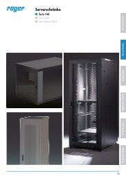
Overvoltage protectionsMiniaRECOMMENDATIONS FOR DESIGN, INSTALLATION AND MEASUREMENT OF OVERVOLTAGE PROTECTIONSINSTALLATION OF OVERVOLTAGE PROTECTIONS1. Installation of lightning currentarresters – T1Lightning current arresters, i.e. the arresters type 1, areinstalled mainly on the interface of zones LPZ0 / LPZ1.The main switchboard is usually placed on this interface.The <strong>devices</strong> are installed on „U“ rail type TH 35 (DIN rail).Installation of the lightning current arresters in meteringswitchboard shall be approved by relevant power distributioncompanies. In not measured part, use the lightningcurrent arresters SJBplus-... or SJB-25E-...2. Installation of compact combined surgevoltage arresters of type T1+T2+We recommend to install the compact combined arrester type1 and 2 (SJBC = spark gap + varistor) in the main switchboardon „U“ rail type TH 35 in case it is possible to unite the boundariesof lightning protection levels LPZ0/LPZ1 and LPZ1/LPZ2.With its parameters and small dimensions, this combinationis suitable for both industrial applications and applications inbuildings, apartments etc.The advantage of combined arrestersis that they provide complete solution for given system(etc. TN-C, TN-S) without the need of interconnecting busbarsetc. -„one device = complete solution“.If it is not possible to unite the boundaries of lightning protectionlevels LPZ0/LPZ1 and LPZ1/LPZ2 (etc. in block of flats- in the unmeasured part there can not be installed varistorbased overvoltage protection, then type SJB-25E-... has tobe used on the boundary of LPZ0/LPZ1 and type SVC-...onthe boundary of LPZ1/LPZ2Combined arrester of lightning current type 1 and type 2(SVBC – varistor) can be used in switchboards of individualflats in cases when it is not possible to install common firstprotection stage (etc. block of flats, where there is not allowedto install in unmeasured part any type of overvoltageprotection). Combined arrester of lightning current SVBC isthank to lightning current separation in several branchesconvenient protection for these applications. It is installedon „U“ rail type TH 35.3. Installation of surge voltage arresters – T2Surge voltage arresters T2 are installed mainly on boundariesof LPZ1 / LPZ2, that means in subsidiary switchboard behindthe arresters of lightning current installed in the mainswitchboard. They are installed on „U“ rail type TH 35. It isnecessary to ensure coordination of individual protectionstages at installation. For more information see paragraph“Coordination of overvoltage protection“.4. Installation of surge voltage arresters – T3Surge voltage arresters T2 are installed on „U“ rail of typeTH 35. If the length of the line between T2 and T310 m we recommend toinstall the overvoltage protection also at the inverter on theDC side.LNPEfig. 1. Continuous connectionLNPEmax. 0.5 mfig. 2. Transversal connectionFFPROTECTION OF OVERVOLTAGE PROTECTIONS1. Protection of lightning currentarresters – T1Protection can be implemented in two ways:protection only by fuses F1 in the service box, if F1correspond to the values stated in the table of technicalparameters of given type. However, if in such wiringthere are leakages and follow short-circuit currents,though the SJB arresters are able to quench the followshort-circuit currents, F1 may blow with subsequentinterruption of power supply in the building.use of fuses F2 in addition to F1 if the latter are too bigor if you do not want to interrupt the power supply. Insuch case selectivity must be ensured between F1 andF2 i.e. I nF1 ≥ 1,6xI nF2 .With this ratio of rated currents, F2 will cut out soonerthan F1, and the power supply of the building will notbe interrupted. However, the values I nF2 may be low,and F2 will blow more frequently. For this reason it isrecommended to equip the fuse F2 with a signallingdevice.2. Protection of surge voltage arresters – T2The previous paragraph applies also to the protectionof surge voltage arresters, however in Wiring diagramexamples these fuses are designated F3.3. Protection of surge voltage arresters – T3Surge voltage arresters SVD shall be protected by circuitbreakers or fuses gG max. 25 A.4. Protection of arresters for connection„3+1“Arresters for connection between N and PE conductors,i.e. the arrester SJB-NPE-1.5 and the module between Nand PE for the other versions are not protected separately.Because their protection is already provided by fuses F1,F2 or F3, see the wiring diagram examples.5.Protection of arresters for photovoltaic systemsIt is not needed to protect the arrester for photovoltaicsystems in any special way. However, in case of twovaristors design and one spark gap the limit of maximumshort-circuit current has to be considered.COORDINATION OF OVERVOLTAGE PROTECTIONThe correct function of multiple stage protection isconditioned by correct coordination of individual stages. Atfirst the most sensitive stage of protection reacts. Before itgets overloaded the superior stage has to react.It is valid in case of T1 and T2 that if their mutual distance isbigger than 10 m (the length of conductors), the coordinationis guaranteed by the physical features of the lines. It meansthat we can use any combination of first and second protectionstage (once we follow other installation instructions).In case we need to install T2 closer to T1, it is necessary to usecombination of overvoltage protection designed for this purpose:T1T2< 5 m 5 ÷ 10 > 10SJBplus-50-2,5 SVM-440-.. SVC-350-.. arbitrarySJB-25E-.. SVC-350-.. SVC-350-.. arbitraryIt is necessary to observe the minimal distance 5 m for thecoordination between the second end the third stages of theprotection.T2> 5 mT3D25