Modular devices
Modular devices
Modular devices
- No tags were found...

You also want an ePaper? Increase the reach of your titles
YUMPU automatically turns print PDFs into web optimized ePapers that Google loves.
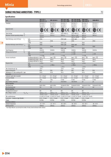
MiniaOvervoltage protectionsSURGE VOLTAGE ARRESTERS - TYPE 2SpecificationsTypeSVC-275-1SVC-275-1-SSVC-255-N-SSVC-350-3-MZSVC-350-3-MZSSVC-350-3N-MZSVC-350-3N-MZSSVM-440-ZSVM-440-ZSSVM-NPE-ZStandards EN 61643-11 EN 61643-11 EN 61643-11 EN 61643-11 EN 61643-11 EN 61643-11IEC 61643-1 IEC 61643-1 IEC 61643-1 IEC 61643-1 IEC 61643-1 IEC 61643-1VDE 0675-6 VDE 0675-6 VDE 0675-6 VDE 0675-6 VDE 0675-6 VDE 0675-6Approval marksRated voltage U N230 V a.c. 230 V a.c. 230 V /400 V a.c. 230 V /400 V a.c. 400 V a.c. 230 V a.c.Maximum constant operating voltage U C275 V a.c. 255 V a.c. 350 V a.c. 350 V a.c. (L-N) 440 V a.c. 260 V a.c.350 V d.c. - - 264 V a.c. (N-PE) 585 V d.c. -Rated discharge current (8/20 μs) I nL-N 20 kA - 20 kA / pole 20 kA / pole 20 kA -N-PE - 30 kA - 20 kA - 20 kAL-PEN 20 kA - 20 kA / pole - 20 kA -Maximum discharge current (8/20 μs) I maxL-N 40 kA - 40 kA / pole 40 kA / pole 40 kA -N-PE - 50 kA - 40 kA - 40 kAL-PEN 40 kA - 40 kA / pole - 40 kA -Rated frequency f n50/60 Hz 50/60 Hz 50/60 Hz 50/60 Hz 50/60 Hz 50/60 HzVoltage protection level U pL-N ≤ 1.35 kV - ≤ 1.4 kV ≤ 1.4 kV ≤ 2.2 kV -N-PE - ≤ 1.3 kV - ≤ 1.5 kV - ≤ 1 kVL-PEN ≤ 1.35 kV - ≤ 1.4 kV - ≤ 2.2 kV -Arrester classification according to EN 61643-11 type 2 type 2 type 2 type 2 type 2 type 2according to IEC 61643-1 class II class II class II class II class II class IIaccording to VDE 0675-6 class C class C class C class C class C class CResponse time L-N ≤ 25 ns - ≤ 25 ns ≤ 25 ns ≤ 25 ns -N-PE - ≤ 100 ns - ≤ 100 ns - ≤ 100 nsL-PEN ≤ 25 ns - ≤ 25 ns - ≤ 25 ns -Max. backup fuse gG / gL 125 A - 125 A 125 A 125 A -Degree of protection IP20 IP20 IP20 IP20 IP20 IP20Mounting on “U” rail according to EN – type TH 35 TH 35 TH 35 TH 35 TH 35 TH 35ConnectionConductor rigid (solid, stranded) 0.5 ÷ 25 mm 2 0.5 ÷ 25 mm 2 0.5 ÷ 35 mm 2 0.5 ÷ 35 mm 2 0.5 ÷ 35 mm 2 0.5 ÷ 35 mm 2Conductor flexible 0.5 ÷ 16 mm 2 0.5 ÷ 16 mm 2 0.5 ÷ 25 mm 2 0.5 ÷ 25 mm 2 0.5 ÷ 25 mm 2 0.5 ÷ 25 mm 2Torque 2 Nm 2 Nm 4.5 Nm 4.5 Nm 4.5 Nm 4.5 NmTop or bottom connection yes yes only bottom only bottom yes yesOptical signallingFunctional state green colour green colour transparent colour transparent colour transparent colour transparent colourNon-functional state red red red red red redRemote signallingArrangement of contacts 1) 001 001 001 001 001 -Max. voltage / current U max/ I max250 V a.c. / 1 A 250 V a.c. / 1 A 250 V a.c. / 1 A 250 V a.c. / 1 A 250 V a.c. / 1 A -125 V d.c. / 0.2 A 125 V d.c. / 0.2 A 125 V d.c. / 0.2 A 125 V d.c. / 0.2 A 125 V d.c. / 0.2 A -Min. switched power 0.12 VA (12 V. 10 mA) 0.12 VA (12 V. 10 mA) 0.12 VA (12 V. 10 mA) 0.12 VA (12 V. 10 mA) 0.12 VA (12 V / 10 mA) -Connection – conductor (rigid, flexible) 0.14 ÷ 1.5 mm 2 0.14 ÷ 1.5 mm 2 0.14 ÷ 1.5 mm 2 0.14 ÷ 1.5 mm 2 0.14 ÷ 1.5 mm 2 -Torque 0.25 Nm 0.25 Nm 0.25 Nm 0.25 Nm 0.25 Nm -Operating conditionsAmbient temperature -25 ÷ 45 °C -25 ÷ 45 °C -40 ÷ 80 °C -40 ÷ 80 °C -40 ÷ 85 °C -40 ÷ 85 °CWorking position arbitrary arbitrary arbitrary arbitrary arbitrary arbitrary1)Each digit indicates successively the number of make, break and break-make contactsD14