Torsion Front Mount Low Headroom Outside ... - Wayne Dalton
Torsion Front Mount Low Headroom Outside ... - Wayne Dalton
Torsion Front Mount Low Headroom Outside ... - Wayne Dalton
- No tags were found...

Create successful ePaper yourself
Turn your PDF publications into a flip-book with our unique Google optimized e-Paper software.
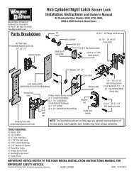
Pre-InstallationImportant Safety InstructionsDefinition of key words used in this manual:WARNINGIndicates a potentially hazardous situation which; if not avoided,could result in severe or fatal injury.Caution: Property damage or injury can result from failure to followinstructions.Important: Required step for safe and proper door operation.Note: Information assuring proper installation of the door.READ THESE INSTRUCTIONS CAREFULLY BEFORE ATTEMPTING INSTALLATION. IF IN QUESTIONABOUT ANY OF THE PROCEDURES, DO NOT PERFORM THE WORK. INSTEAD, HAVE A TRAINEDDOOR SYSTEMS TECHNICIAN DO THE INSTALLATION OR REPAIRS.1. READ AND FOLLOW ALL INSTALLATION INSTRUCTIONS.2. Wear protective gloves during installation to avoid possible cuts from sharp metal edges.3. It is always recommended to wear eye protection when using tools, otherwise eye injurycould result.4. Avoid installing your new door on windy days. Door could fall during the installation causingsevere or fatal injury.5. Doors 12’-0” wide and over should be installed by two persons, to avoid possible injury.6. Operate door only when it is properly adjusted and free from obstructions.7. If a door becomes hard to operate, inoperative or is damaged, immediately have necessaryadjustments and/ or repairs made by a trained door system technician using propertools and instructions.8. DO NOT stand or walk under a moving door, or permit anybody to stand or walk under anelectrically operated door.9. DO NOT place fingers or hands into open section joints when closing a door. Use lifthandles/ gripping points when operating door manually.10. DO NOT permit children to operate garage door or door controls. Severe or fatal injurycould result should the child become entrapped between the door and the floor.11. Due to constant extreme spring tension, do not attempt any adjustment, repair or alterationto any part of the door, especially to springs, spring brackets, bottom corner brackets,fasteners, counterbalance lift cables or supports. To avoid possible severe or fatal injury,have any such work performed by a trained door systems technician using proper toolsand instructions.12. On electrically operated doors, pull down ropes must be removed and locks must beremoved or made inoperative in the open (unlocked) position.13. Top section of door may need to be reinforced when attaching an electric opener. Checkdoor and/ or opener manufacturer’s instructions.14. Visually inspect door and hardware monthly for worn and or broken parts. Check toensure door operates freely.15. Test electric opener’s safety features monthly, following opener manufacturer’s instructions.16. NEVER hang tools, bicycles, hoses, clothing or anything else from horizontal tracks. Tracksystems are not intended or designed to support extra weight.17. This door may not meet the building code wind load requirements in your area. For yoursafety, you will need to check with your local building official for wind load code requirementsand building permit information.After installation is complete, fasten this manual near the garage door.Important: Stainless steel or pt2000 coated lag screws must be used wheninstalling center bearing brackets, end brackets, jamb brackets, drawbar operatormounting/ support brackets and disconnect brackets on treated lumber(preservative-treated). Stainless steel or pt2000 lag screws are not necessarywhen installing products on un-treated lumber.Note: It is recommended that 5/16” lag screws are pilot drilled using a 3/16” drill bit, prior tofastening.Important: When installing 5/16” lag screws using an electric drill/ driver, thedrill/ drivers clutch must be set to deliver no more than 200 in-lbs of torque.Fastener failure could occur at higher settings.WARNINGPrior to winding or making adjustments to the springs, ensureyou’re winding in the proper direction as stated in the InstallationInstructions. Otherwise, the spring fittings may releasefrom spring if not wound in the proper direction and couldresult in severe or fatal injury.Important: Right and left hand is always determined from inside the buildinglooking out.• Power drill• Drill bits: 1/8”, 3/16”,9/32”, 7/16”, 1/2”• Ratchet wrench• Socket driver: 7/16”• Sockets: 7/16”, 1/2”,9/16”, 5/8”Tools Required• Phillips headscrewdriver• Locking Pliers• (2) Vice clamps• Wrenches: 3/8”,7/16”, 1/2”, 9/16”,5/8”• 1/4” Torx bit• Approved windingrodsPackage Contents• Hammer• Tape measure• Step Ladder• Level• Pencil• Leather gloves• Safety glassesNote: Depending on the door model, some parts listed will not be supplied if not required. RearBack Hangs may not be included with your door.Fully Adjustable jambbrackets (as required)Graduated hinges(2) Lift handles& spacersBottom corner bracketsWeather seals & nails(If included)Track rollers(1) Step plate -InsideDoor sections (as required)<strong>Torsion</strong> shaftFully Adjustable flag angles RH/LH(as required)Bottom weather sealStruts (as required)(1) Step plate -outsideDrawbar operatorbracket (if included)Vertical tracks RH/LHHorizontal tracks RH/LH(2) Top fixturesWashers (as required)Pull downrope (if included)Center bracket3Please Do Not Return This Product To The Store. Contact your local <strong>Wayne</strong>-<strong>Dalton</strong> dealer. To find your local <strong>Wayne</strong>-<strong>Dalton</strong> dealer,refer to your local yellow pages business listings or go to the Find a Dealer section online at www.<strong>Wayne</strong>-<strong>Dalton</strong>.com
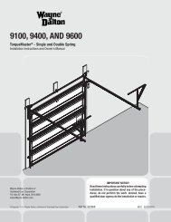
for tracks, springs, etc. to allow the door to open properly. If the door is to be motor operated,2-1/2” (64 mm) of additional headroom is required.Backroom requirement: Backroom is defined as the distance needed from the opening backinto the garage to allow the door to open fully.Backroom RequirementsDOOR HEIGHT TRACK MANUAL LIFT MOTOR OPERATED6’0” to 7’0” 12”,15” Radius 102” (2591 mm) 125” (3175 mm)7’1” to 8’0” 12”,15” Radius 114” (2896 mm) 137” (3480 mm)<strong>Headroom</strong> RequirementsTRACK TYPESPACE NEEDED3” LHR 6-1/2” (165 mm)6” LHR 9” (229 mm)Suitable mounting surface2”x 6” lumber minimumHeader board 2”x 6”lumber preferred<strong>Headroom</strong>Min. SideroomClearanceis 3 1/2”Min. SideroomClearanceis 3 1/2”FinishedDoorHeightLevel headerWeatherstripsNailBackroomPlumbjambsJambsFinishedDoor widthJambQuick Install trackJambFully Adjustable track1/8” to 1/4”WeatherstripsWeatherstrips5Please Do Not Return This Product To The Store. Contact your local <strong>Wayne</strong>-<strong>Dalton</strong> dealer. To find your local <strong>Wayne</strong>-<strong>Dalton</strong> dealer,refer to your local yellow pages business listings or go to the Find a Dealer section online at www.<strong>Wayne</strong>-<strong>Dalton</strong>.com
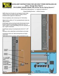
InstallationBefore installing your door, be certain that you have read and followed all of the instructionscovered in the pre-installation section of this manual. Failure to do so may result in animproperly installed door.NOTE: Reference TDS 160 for general garage door terminology at www.dasma.com.1Fully Adjustable Flag AnglesTools: NoneNote: If you have Quick Install flag angles, skip this step.Note: If you have riveted track, skip this step.Note: Flag angles are right and left handed.If you have Quick Install vertical tracks, hand tighten the left hand flag angle to the left handvertical track using (1) stud plate and (2) 1/4” – 20 flange hex nuts. Repeat for the other side.If you have Fully Adjustable vertical tracks, hand tighten the left hand flag angle to the lefthand vertical track using (2) 1/4”-20 x 9/16” track bolts and (2) 1/4”-20 flange hex nuts.Repeat for other side. Flange nuts will be secured after flag angle spacing is completed instep, Top Section.Flag angle1/4”-20Flange hex nutsQuick Installverticaltrack2StudplateFlag angle1/4”-20Flange hex nutsFully AdjustableverticaltrackFully Adjustable Jamb BracketsTools: None1/4”- 20 x 9/16”Track boltsNote: If you have Quick Install jamb brackets, skip this step.Note: If you have riveted track, skip this step.Note: The bottom jamb bracket is always the shortest bracket, while the center jambbracket is the next tallest. If three jamb brackets per side are included with your door, you willhave received a top jamb bracket, which is the tallest.To attach the bottom jamb bracket, locate lower hole of the hole/ slot pattern of the 1st holeset on the vertical track. Align the slot in the jamb bracket with the lower hole of the hole/ slotpattern. Secure jamb bracket using (1) 1/4”-20 x 9/16” track bolt and (1) 1/4”-20 flange hexnut. Repeat for other side.Place the center jamb bracket over the lower hole of the hole/ slot pattern that is centeredbetween the bottom jamb bracket and flag angle of the 2nd hole set. Secure jamb bracketusing (1) 1/4”-20 x 9/16” track bolt and (1) 1/4”-20 flange hex nut. Repeat for other side.If a top jamb bracket was included, secure it to vertical track using the lower hole of the hole/slot pattern in the 3rd hole set and (1) 1/4”-20 x 9/16” track bolt and (1) 1/4”-20 flange hexnut. Repeat for other side.1st hole set2nd hole set3rd hole setVertical trackTop of tracksection.Align the ends of the bottom weather seal with the bottom of the section and attach with1/4”-14 x 7/8” self drilling screws, one on each end at least 6” from the end of the sectionand one every 18” in between.4Bottom section1/4”-14 x 7/8”Self drillingscrewsBottomweather seal1/4”-14 x 7/8” Selfdrilling screwsBottom sectionBottomweather seal 6” 18” 18” 18” 18” 6”Counterbalance Lift CablesTools: Power Drill, 7/16” Socket driver, Tape measureNOTE: Refer to door section identification, located in the pre-installation section of thismanual.Starting on the left hand side, attach left hand bottom corner bracket to the left corner of thebottom section, making sure it is seated to the edges of the end cap, with (5) 1/4”-14 x 7/8”self drilling screws and (1) 1/4”-14 x 5/8” tamper resistant self drilling screw. Repeat forother side.NOTE: All doors are provided with the tamper resistant fastener for the bottom cornerbrackets. However, the professional installer is most likely to have the proper tool to installthis fastener. If the homeowner does not have the proper tool to install the tamper resistantfastener, use a regular 1/4”-14 x 7/8” self drilling screw in its place.WARNINGFailure to ensure tight fit of cable loop over milford pin couldresult in cable coming off the pin, allowing the door to fall,possibly resulting in severe or fatal injury.Uncoil the counterbalance lift cables. Place clevis pin into the inside tab of the bottom cornerbracket and slide the cable loop of the counterbalance lift cable onto pin. Continue slidingclevis pin thru the outside tab of the bracket. Place a washer onto mildford pin and secure inplace using a cotter pin, as shown.Insert a short stem track roller into the bottom corner bracket. Repeat for other side.NOTE: Verify bottom weather seal (bottom seal) is aligned with door section. If there is morethan 1/2” excess bottom weather seal on either side, trim bottom weather seal even withdoor section.End capEnd capBottomsectionLeft handbottom cornerbracketBottomweatherseal(5) 1/4”-14 x 7/8”Self drillingscrewsLeft handbottomcornerbracket1/4”-14 x 5/8” Tamperresistant self drilling screwBottom section<strong>Low</strong>er hole ofhole/ slot pattern1/4”- 20Flange hex nutF.A. jambbracket1/4”- 20 x9/16”Track boltJamb bracketin placeCounterbalancelift cableWasherClevis pinBottom weathersealCounterbalancelift cable3Bottom Weather SealTools: Power Drill, 7/16” Socket driver, Tape measureNOTE: Refer to door section identification, located in the pre-installation section of thismanual.Determine what size section you need to use for the bottom section. Select proper bottomShort stemtrack rollerCotterpinLeft handbottom cornerbracket6Please Do Not Return This Product To The Store. Contact your local <strong>Wayne</strong>-<strong>Dalton</strong> dealer. To find your local <strong>Wayne</strong>-<strong>Dalton</strong> dealer,refer to your local yellow pages business listings or go to the Find a Dealer section online at www.<strong>Wayne</strong>-<strong>Dalton</strong>.comWasherCotter pinClevis pin
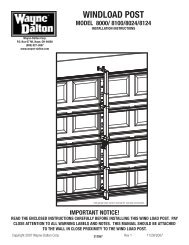
5Graduated Hinge AttachmentTools: Power drill,7/16” Socket driverNOTE: Refer to door section identification, located in the pre-installation section of thismanual.NOTE: The graduated hinges can be identified by the number stamped onto their lower hingeleaf.Locate the bottom section, (2) #1 graduated end hinges (wide body) for the end stiles anddepending on the width of your door, enough #1 center hinge(s) (narrow body) for each ofthe pre-marked center hinge locations. Starting on the left hand side of the bottom section,align the lower hinge leaf of the #1 graduated end hinge over the holes, located at the topof the end caps. Also, align the lower hinge leafs of the #1 center hinges (narrow body) withthe pre-marked locations at the center locations at the top of the section. Attach lower hingeleafs to the section using (2) 1/4”-14 x 7/8” self drilling screws.IMPORTANT: Once the 1/4”-14 x 7/8” self drilling screws are snug against thelower hinge leafs, tighten an additional 1/4 to 1/2 turn to receive maximumdesign holding power.Important: Push & hold the hinge leaf securely against the section whilesecuring with 1/4”-14 x 7/8” self drilling screws. There should be no gapbetween the hinge leaf and the section.Place a short stem track roller into each graduated end hinge. Repeat graduated hingeattachment using the appropriate graduated end hinges for all remaining sections except thetop section.IMPORTANT: When placing short stem track rollers into the #2 graduatedend hinges and higher, the short stem track roller goes into hinge tubefurthest away from section.Use (2) #2 graduated end hinges (wide body) and the required number of #1 center hinge(s)(narrow body) for each of the center hinge pre-marked location(s) along the top edge of thelock section (second section).Use (2) #3 graduated end hinges (wide body) and the required number of #1 center hinge(s)(narrow body) for each of the center hinge(s) (narrow body) pre-marked location(s) along thetop edge of the intermediate I section (third section).Use (2) #4 graduated end hinges (wide body) and the required number of #1 center hinge(s)(narrow body) for each of the center hinge pre-marked location(s) along the top edge of theintermediate II section (third section).Short stemtrack roller#1 Graduated endhinge (Wide body)<strong>Low</strong>er leaf(2) 1/4”-14 x 7/8” Selfdrilling screw locationsPre-punchedholes inendstiles#1Center hinge(s)(Narrow body)#2 Graduated end hinge(roller inserted into tubefurthest from section)Pre-markedlocations onsection surfaceStrutting ScheduleSection Quantity45Strut installationfor top sectionStrut installationfor other sectionsStrut7SectionSolid / WindowsDoor Width6’0” – 10’0” 12’0” 13’0” – 18’0”Top Solid N/A 1 1Windows 1 1 1Intermediate Solid N/A N/A N/AWindows 1 1 N/ALock Solid N/A N/A N/ABottom N/A N/A 1Top Solid N/A 1 1Windows 1 1 1Intermediate II Solid N/A N/A N/AWindows 1 1 N/AIntermediate Solid N/A N/A 1Windows 1 1 1Lock Solid N/A N/A N/ABottom Windows N/A N/A 1Strut installation attop of top sectionEnd hingesTypical upperhinge leaf1/4”-14 x 7/8” Self drillingscrewsCenter hinge(s)1/4”-14 x 7/8” Self drillingscrewsTypical lowerhinge leafStrut installation for other sectionsStrutTop FixturesTools: Power drill, 7/16” Socket driver, (2) Saw horses, Tape measureRemove, but retain the 1/4”-14 x 7/8” self drilling screws from the right side of the strut,allowing enough room to slide the top fixture between the top section and the strut (if applicable).Slide the top fixture between the strut and top section. Align the edge of the top fixtureparallel to the top section edge. Secure the top fixture to the top section using (1) 1/4”-14 x7/8” self drilling screw through the lower slot of top fixture. Adjust the top fixture, if necessary.Finish re-attaching the strut using the (2) 1/4”-14 x 7/8” self drilling screws removedpreviously. Insert a short stem track roller into top fixture. Repeat for left hand side.TopsectionStrut(if applicable)Short stemtrack roller6Strut AttachmentTools: Power drill, 7/16” Socket driver, (2) Saw horses, Tape measureNOTE: Refer to door section identification, located in the pre-installation section of thismanual to determine what size sections you need to use as your lock (second) section, intermediateI (third) section, intermediate II (fourth section on a five section door) and top section.Measure your sections to make sure they are the correct height as indicated on the chart.NOTE: Depending on the size of your door, one or more sections may require a strut.Using sawhorses, lay sections together on a flat smooth surface. Ensure the hinges are ontop of their corresponding sections. Referring to the strutting schedule, determine how manystruts your door needs and on what sections they are needed to be installed.NOTE: Sections not noted in the strutting schedule, do not require a strut.NOTE: All strut(s) are placed at the top of the section.INSTALLATION ON ALL SECTIONS (EXCEPT TOP SECTION): Place the strut on the sectionup against the bottom of the hinges. Center the strut side to side on the section as shown.Secure to the section using (2) 1/4”-14 x 7/8” self drilling screws at each end hinge locationand (2) 1/4”-14 x 7/8” self drilling screw at each center hinge location.INSTALLATION ON TOP SECTION: Place the strut on the top section, center the strut sideto side on the top edge of the top section. Loosely fasten to the section using (2) 1/4”-14x 7/8” self drilling screws at each endstile. The 1/4”-14 x 7/8” self drilling screws for theendstiles will be secured after step, Top Fixture is completed. Next, secure strut to the sectionusing (2) 1/4”-14 x 7/8” self drilling screw at each center hinge location at each pre-markedlocation.7(3) 1/4”-14 x 7/8”Self drilling screwsEnd capPlease Do Not Return This Product To The Store. Contact your local <strong>Wayne</strong>-<strong>Dalton</strong> dealer. To find your local <strong>Wayne</strong>-<strong>Dalton</strong> dealer,refer to your local yellow pages business listings or go to the Find a Dealer section online at www.<strong>Wayne</strong>-<strong>Dalton</strong>.com8Top fixturebaseStep PlateTools: Power Drill, 7/16” Drill Bit, Phillips Screwdriver, Tape MeasureNOTE: Refer to door section identification, located in the pre-installation section of thismanual.On the inside of the bottom section, locate the vertical center of the door.Center the inside step plate vertically no higher than 8” from the bottom of the door to thetop of the step plate.IMPORTANT: Do not mount the step plate higher than 8” from the bottom ofthe section.Using the inside step plate’s second top most hole and bottom hole as a template, drill 7/16”diameter holes through the entire section.NOTE: Be extremely careful to keep drill straight when drilling through the section.
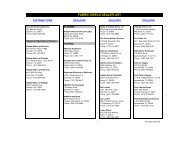
Now insert the outside step plate into the holes through the front of the door, mounting thetwo step plates back to back. Secure step plates together with two No. 8 screws through theinside step plate and into the outside step plate.Bottom section insideBottom section outsideDrill (1) 7/16”diameter hole ateach marked7/16” Diameter holeslocationWeather seal8” Max.mountingheightInside step plate(2) #8 Screws<strong>Outside</strong> step plateLevel9Lift HandleTools: Pencil, Power Drill, (9/32, 1/2”) Drill Bits, (2) Saw horses, TapeMeasure, 7/16” WrenchNOTE: Refer to door section identification, located in the pre-installation section of thismanualUsing sawhorses, lay the bottom and lock sections together on a flat smooth surface. Ensurethe hinges are on top of their corresponding sections.Locate the vertical center of the lock (second) section of the door and position the lifthandle’s bottom hole 4” from the bottom of the lock section along the vertical center on theoutside of the door. Use the holes in the lift handle as a template to mark the hole locations.IMPORTANT: The lift handle and the step plate need to be vertically aligned.Drill 9/32” diameter holes through the section at each marked location. Enlarge the holesfrom outside the door to 1/2” diameter through the section. Assemble the outside and insidelift handles to the section using (2) 1/4” x 2-1/2” carriage bolts and (2) 1/4”-20 hex nuts andspacers.WARNINGTo avoid possible injury, lift handles that are installed within4 inches (102mm) of a section interface shall promote verticalorientation of the hand.1/2” Diameter holesLock sectionoutsideLock sectioninside11Wooden shims(If necessary)Bottom sectionVertical TracksTools: Power Drill, 3/16” Drill bit, 7/16” Socket driver, Tape measure,Level, Step ladderIMPORTANT: If your door is to be installed prior to a finishing constructionof the building’s floor, the vertical tracks and the door bottom sectionassembly should be installed such that when the floor is constructed, nodoor or track parts are trapped in the floor construction.Important: The tops of the vertical tracks must be level from side to side.If the bottom section was shimmed to level it, the vertical track on theshimmed side must be raised the height of the shim.Position the left hand vertical track assembly over the track rollers of the bottom section.Make sure the counterbalance lift cable is located between the track rollers and the doorjamb. Drill 3/16” pilot holes into the door jamb for the lag screws.Loosely fasten jamb brackets and flag angle to the jamb using 5/16” x 1-5/8” lag screws.Tighten lag screws, securing the bottom jamb bracket to jamb, maintain 3/8” to 5/8” spacing,between the bottom section and vertical track. Hang counterbalance lift cable over flagangle. Repeat same process for other side.4”(2) SpacersLift handleLift handleFlagangle(2) 1/4” x 2-1/2” Carriage bolts10Bottom SectionTools: Level, Wooden shims (if necessary)(2) 1/4”-20 hex nutsCenter the bottom section in the door opening. Level the section using wooden shims (ifnecessary) under the bottom section.VerticaltrackassemblyJambbracketBottomsection5/16” x 1-5/8”Lag screwsTrackrollers12R FA 15R FA 12R QI 15R QIFlag angle lag screw locations3/8” to 5/8”SpacingBottom sectionVertical trackFloorTrack roller12Stacking SectionsTools: Power drill,7/16” Socket driver8Note: Refer to door section identification, located in the pre-installation section of thismanual.Note: The sections can be identified by the graduation of the factory installed graduated endhinges. The smallest graduated end hinge on section should be stacked on top of the bottomsection, with each graduated end hinge increasing as the sections are stacked, see PartsBreakdown on page 2.Note: Make sure end and center hinges are flipped down, when stacking another sectionon top.Place track rollers into graduated end hinges of remaining sections.Please Do Not Return This Product To The Store. Contact your local <strong>Wayne</strong>-<strong>Dalton</strong> dealer. To find your local <strong>Wayne</strong>-<strong>Dalton</strong> dealer,refer to your local yellow pages business listings or go to the Find a Dealer section online at www.<strong>Wayne</strong>-<strong>Dalton</strong>.com
To install horizontal track, place the top rail end over the top track roller of the top section.Align key slot of the bottom rail end of horizontal track with the Quick Install tab of the flagangle. Push curved portion of horizontal track down to lock in place.WARNINGDo not raise door until horizontal tracks are secured at rear,as outlined in Step, Rear Back Hangs, or door could fall fromoverhead position causing severe or fatal injury.Level the horizontal track assembly and bolt the top rail of the horizontal track to the encounteredslot in the flag angle using (1) 1/4”-20 x 9/16” track bolt, (1) 1/4”-20 flange hex nutand (1) 5/16 washer. Repeat for other side.Remove the nail that was temporarily holding the top section in place, installed in step, TopSection.Important: Failure to remove nail before attempting to raise door couldcause permanent damage to top section.Note: If an idrive ® opener will be installed, position horizontal tracks slightly above level.Flag angleBottom railof horizontaltrackQuickInstalltabVerticaltrack16Quick Installtab in placeTracks flushKey slotVerticaltrackFlagangle1/4”-20 x 9/16”Track boltWasherTop rail ofhorizontaltrack1/4”-20Flange hexnutHorizontal Tracks/F.A. Flag AnglesTools: Ratchet wrench, 7/16” Socket, 9/16” Socket, 9/16” Wrench,level, Step ladder, Flat tip screwdriveredge of the end bearing bracket with the right edge of the flag angle.Secure the end bearing bracket to the jamb using (3) 5/16” x 1-5/8” lag screws, as shown.Repeat same process for the other side.Top edgeof flagangle18BottomedgeLeft end bearingbracketTopsectionLeft end bearingbracket(3) 5/16” x 1-5/8”Lag screwsTopsectionCenter Bracket Bushing AssemblyTools: Step ladder, Power drill, 7/16” Socket driver, 1/4” Torx bit, Level,Tape measure, PencilLocate the center of the door. Mark a vertical pencil line on the mounting surface abovethe door, at the center. Measure from the center of the bearing, in one of the end bearingbrackets, downwards, to the top the door. Using that measurement, measure that distanceupwards from the top of the door to the mounting surface and mark a horizontal pencil linewhich intersects the vertical pencil line. Align the edge of the center bracket with the verticalpencil line and the center of the center bracket with the horizontal pencil line; this is toensure the torsion shaft is level between the center and end bearing brackets.Attach the center bracket to the mounting surface, using (2) 5/16” x 1-5/8” lag screws and(1) 5/16” x 2” tamper-resistant lag screw.IMPORTANT: Use a 5/16” x 1-5/8” tamper-resistant lag screw instead of the5/16” x 2” tamper-resistant lag screw if mounting surface is mounted overmasonry. Tamper-resistant lag screw must be attached through the bottomhole of the center bearing bracket.Note: If you have Fully Adjustable flag angles, complete this step.To install horizontal track, place the top rail end over the top track roller of the top section.Align the bottom rail end of the horizontal track with the top of the vertical track. If you haveQuick Install horizontal track, tighten the bottom rail of the horizontal track to the flag anglewith (1) stud plate and (2) 1/4”-20 flange hex nuts. If you have Universal horizontal track,tighten the bottom rail of the horizontal track to the flag angle with (2) 1/4”-20 x 9/16” trackbolts and (2) 1/4”-20 flange hex nuts.WARNINGDo not raise door until horizontal tracks are secured at rear,as outlined in step, Rear Back Hangs, or door could fall fromoverhead position causing severe or fatal injury.Level the horizontal track assembly and bolt the top rail of the horizontal track to the encounteredslot in the flag angle using (1) 1/4”-20 x 9/16” track bolt, (1) 1/4”-20 flange hex nutand (1) 5/16 washer. Repeat for other side.Remove the nail that was temporarily holding the top section in place, installed in step, TopSection.Important: Failure to remove nail before attempting to raise door couldcause permanent damage to top section.Note: If an idrive ® opener will be installed, position horizontal tracks slightly above level.Bottom railQuick InstallHorizontaltrack1/4”-20Flange hexnutsBottom rail FullyAdjustableHorizontaltrack1/4”-20Flange hexnutsFlagangleFlag angleFlag angleupper slot upper slot1/4”-20VerticalVerticalFlange hextracktracknutStud plate 1/4”-20 x 9/16” Track bolts17End Bearing BracketsTools: Step ladder, Power drill, 7/16” Socket driver1/4”-20 x 9/16”Track boltWasherTop rail ofhorizontaltrackNOTE: Right and left hand is always determined from inside the garage looking out.End bearing brackets are right and left hand. Align the bottom edge of left end bearingbracket with the top edge of the flag angle. Maintaining this alignment, also align the right1019<strong>Mount</strong>ing surfaceCenter of endbearing bracketVertical line(2) 5/16” x 1-5/8”Lag screwsHorizontal line<strong>Mount</strong>ing surfaceHorizontal lineVertical linePlease Do Not Return This Product To The Store. Contact your local <strong>Wayne</strong>-<strong>Dalton</strong> dealer. To find your local <strong>Wayne</strong>-<strong>Dalton</strong> dealer,refer to your local yellow pages business listings or go to the Find a Dealer section online at www.<strong>Wayne</strong>-<strong>Dalton</strong>.comCenterbracketEqual distance (top of door section to horizontal line)Centerbracket<strong>Torsion</strong> Spring AssemblyTools: Step Ladder(1) 5/16” X 2” or (1) 5/16” x 1-5/8”Tamper-resistant lag screwIMPORTANT: Right and left hand is always determined from inside the buildinglooking out.
NOTE: Identify the torsion springs provided as either right hand wound (red winding cone),which goes on the RIGHT HAND SIDE or left hand wound (black winding cone), which goes onthe LEFT HAND SIDE.Facing the inside of the door, lay the torsion shaft on the floor. Lay the torsion spring with theblack winding cone and the red cable drum at the left end of the torsion shaft. Lay the torsionspring with the red winding cone and the black cable drum at the right end of the torsionshaft.NOTE: The set screws used on all torsion winding cones and cable drums are now coloredred. DO NOT identify right and left hand by the set screw color.Slide the center bracket bushing onto the torsion shaft followed by the torsion springs andcable drums.IMPORTANT: The center bracket bushing, torsion springs, and cable drumsmust be positioned, as shown.With assistance, pick up the torsion spring assembly and slide one end of the torsion shaftthrough one end bearing bracket. Lay the middle of the torsion shaft into the center bracket.Slide the other end of the torsion shaft into the other end bearing bracket. Position the torsionshaft so that equal amounts of the shaft extend from each end bearing brackets.Black cable drum(right hand side)Center bracketStationaryspring cone<strong>Torsion</strong>spring(2) 3/8”-16 NutsCenter bracketbushingSpringwarning tagsStationaryspring coneCenter bracketbushing assembly<strong>Torsion</strong> springRed cable drum(left hand side)<strong>Torsion</strong> shaftRight hand wound,red winding cone(right hand side)<strong>Torsion</strong>spring<strong>Torsion</strong>springLeft hand wound,black winding cone(left hand side)Center bracketbushing21Stationary spring cone(2) 3/8”-16 x 1-1/2”Hex head boltsCounterbalance Lift CablesTools: Step Ladder, Locking Pliers, 3/8” Wrench20Left hand endbearing bracket<strong>Torsion</strong> shaftRed cable drumCenter bracketbushing assembly<strong>Torsion</strong> shaftEqual spacingCenterbracketbushingCenter bracket<strong>Torsion</strong> Spring AttachmentTools: Step Ladder, 1/2” WrenchRight hand endbearing bracketBlack cable drum<strong>Torsion</strong> spring(s)Slide the center bracket bushing into the center bracket. Align the stationary spring cone(s)with the holes in the center bracket bushing assembly. Secure the torsion spring(s) to thecenter bracket bushing assembly with (2) 3/8”-16 x 1-1/2” hex head bolts and (2) 3/8”-16nuts.IMPORTANT: The spring warning tag(s) supplied must be securely attachedto the stationary spring cone(s) in plain view. Should a replacement springwarning tag be required, contact <strong>Wayne</strong>-<strong>Dalton</strong> for free replacements.Starting on the left hand side, thread the counterbalance lift cable up and around the frontside of the left hand cable drum.IMPORTANT: Verify that there are no counterbalance lift cable obstructions.Hook the counterbalance lift cable into the left hand cable drum. Slide the left hand cabledrum onto the torsion shaft and up against the left hand end bearing bracket. Counterbalancelift cable should terminate at the 9 o’clock position. Tighten the (2) set screws in thecable drum to 14-15 ft. lbs. of torque (once set screws contact the shaft, tighten set screwsone full turn). Rotate the left hand drum and torsion shaft until counterbalance lift cable istaut. Now attach locking pliers to the torsion shaft and brace locking pliers up against thejamb to keep counterbalance lift cable taut.Repeat for right hand side.IMPORTANT: Inspect each counterbalance lift cables making sure they areseated properly onto the cable drums and that both counterbalance liftcables have equal tension.Left handend bearing JambbracketCounterbalance liftcable installed22<strong>Torsion</strong>shaftLockingpliersLeft handcabledrumCable drumset screwsCounterbalance lift cableSecuring Door For Spring Winding(s)Tools: Vice Clamps11With the door in the fully closed position, place vice clamps onto both vertical tracks justabove the third track roller. This is to prevent the garage door from rising while windingsprings.WARNINGFailure to place vice clamps onto vertical track can allowdoor to raise and cause severe or fatal injury.Please Do Not Return This Product To The Store. Contact your local <strong>Wayne</strong>-<strong>Dalton</strong> dealer. To find your local <strong>Wayne</strong>-<strong>Dalton</strong> dealer,refer to your local yellow pages business listings or go to the Find a Dealer section online at www.<strong>Wayne</strong>-<strong>Dalton</strong>.com
WHEN CONNECTING A TROLLEY TYPE GARAGE DOOROPENER TO THIS DOOR, A WAYNE-DALTONOPENER/TROLLEY BRACKET MUST BE SECURELYATTACHED TO THE TOP SECTION OF THE DOOR, ALONGWITH ANY U-BARS PROVIDED WITH THE DOOR. THEINSTALLATION OF THE OPENER MUST BE ACCORDING TOMANUFACTURER’S INSTRUCTIONS AND FORCE SETTINGSMUST BE ADJUSTED PROPERLY.<strong>Wayne</strong> <strong>Dalton</strong>, a Division of <strong>Wayne</strong> <strong>Dalton</strong>, a Division ofOverhead Door Corp.Overhead Door Corp.3395 Addison Dr.P.O. Box 67Pensacola, FL 32514Mt. Hope, OH 44660www.wayne-dalton.comwww.wayne-dalton.comSAFETY INSTRUCTIONS1. Operate door ONLY when it is properlyadjusted and free of obstructions.2. If a door becomes hard to operate,inoperative or is damaged, immediatelyhave necessary adjustments and/or repairsmade by a trained door system technicianusing proper tools and instructions.3. DO NOT stand or walk under a moving door,or permit anybody to stand or walk underan electrically operated door.4. DO NOT place fingers or hands into opensection joints when closing a door. Use lifthandles/gripping points when operatingdoor manually.5. DO NOT permit children to operate garagedoor or door controls.6. Due to constant extreme spring tension,DO NOT attempt any adjustment, repair oralteration to any part of the door,especially to springs, spring brackets,bottom corner brackets, red coloredfasteners, cables or supports. To avoidpossible severe or fatal injury, have anysuch work performed by a trained doorsystem technician using proper tools andinstructions.7. On electrically operated doors, pull downropes must be removed and locks must beremoved or made inoperative in the open(unlocked) position.8. Top section of door may need to bereinforced when attaching an electricopener. Check door and/or openermanufacturer’s instructions.9. VISUALLY inspect door and hardwaremonthly for worn and/or broken parts.Check to ensure door operates freely.10. Test electric opener’s safety featuresmonthly, following opener manufacturer’sinstructions.11. NEVER hang tools, bicycles, hoses, clothingor anything else from horizontal tracks.Track systems are not intended or designedto support such extra weight.Place label at a readable height on door. DO NOTremove, cover or paint over this label. Productuser should inspect this label periodically forlegibility and should order a replacement labelfrom the door manufacturer as needed.HIGH SPRING TENSION CAN CAUSESERIOUS INJURY OR DEATH.DO NOT adjust, repair or remove springs orparts to which springs are connected, suchas steel brackets, cables, wood blocks,fasteners or other parts of thecounterbalance system.Adjustments or repairs must ONLY be madeby a trained door systems technician usingproper tools and instructions.DO NOT remove, cover or paint over this tag.Product user should inspect this tagperiodically for legibility and should order areplacement tag from the doormanufacturer, as needed.If door still does not balance correctly, contact a qualified door agency. If the door still doesnot operate easily, lower the door into the closed position, UNWIND THE SPRING(S) FULLY(Reference the insert “Removing The Old Door/Preparing The Opening” section on torsionspring removal), and recheck the following the items:1.) Check the door for level.2.) Check the torsion shaft for level.3.) Check the track spacing.4.) Check the counterbalance lift cables for equal tension.5.) Check the track for potential obstruction of the track rollers.6.) Clamp locking pliers onto track and rewind springs.IMPORTANT: If door still does not operate properly, then contact a trained door systemtechnician.(3) 5/16”Bolts and nutsSound framingmembersHorizontal tracksHorizontaltrackPerforated angle5/16”-18 x 1-1/4”Hex bolts must extend into thetrack to serve as a roller stopPerforated angle boltedusing (2) 5/16” x 1-5/8”hex head lag screws toceiling member andparallel to doorVice clamp2nd Track rollerVice clamp3/4” To 7/8” 3/4” To 7/8”Door edgesHorizontal tracksSound framingmembers25Label PlacementTools: Step LadderIMPORTANT: Using the illustration, attach the appropriate labels to the appropriatelocation on the section, as shown.NOTE: The Spring Warning tag(s) are factory attached (one per spring).NOTE: Because of different configurations, some labels may require minor relocations.Factory Attached, <strong>Torsion</strong> spring tag(s) (one per spring)IMPORTANT!Horizontaltrack5/16”-18 x 1-1/4”Hex bolts must extend into thetrack to serve as a roller stopPerforated angle boltedusing (2) 5/16” x 1-5/8”hex head lag screws toceiling member andparallel to door(3) 5/16” Bolts and nutsPerforated angleWARNINGLift handles/gripping points are requiredon this door, located as spelled out in theinstallation instructions, even if the dooris motor operated.Operatorbracket labelResidentialwarning labelWARNINGLift handles/gripping points are requiredon this door, located as spelled out in theinstallation instructions, even if the dooris motor operated.Failure to install and use these lift handles/gripping points on this door can result inserious injury to fingers and/or hands, ifplaced in the opening between sections,when the door is operated manually.WARNINGThe adjacent bottom corner bracket andall cable retention features includingmilford pins, cotter pins, & clevis pins areunder HIGH SPRING TENSION.Failure to install and use these lift handles/gripping points on this door can result inserious injury to fingers and/or hands, ifplaced in the opening between sections,when the door is operated manually.WARNINGThe adjacent bottom corner bracket andall cable retention features includingmilford pins, cotter pins, & clevis pins areunder HIGH SPRING TENSION.Adjustments and repairs must only bemade by a trained door systemstechnician, using proper tools andinstructions.DO NOT REMOVE, COVER OR PAINT OVERTHIS LABEL. PRODUCT USER SHOULDINSPECT THIS LABEL PERIODICALLY FORLEGIBILITY AND SHOULD ORDER AREPLACEMENT FROM THE DOORMANUFACTURER AS NEEDED.Bottom section warning labelsAdjustments and repairs must only bemade by a trained door systemstechnician, using proper tools andinstructions.DO NOT REMOVE, COVER OR PAINT OVERTHIS LABEL. PRODUCT USER SHOULDINSPECT THIS LABEL PERIODICALLY FORLEGIBILITY AND SHOULD ORDER AREPLACEMENT FROM THE DOORMANUFACTURER AS NEEDED.13Please Do Not Return This Product To The Store. Contact your local <strong>Wayne</strong>-<strong>Dalton</strong> dealer. To find your local <strong>Wayne</strong>-<strong>Dalton</strong> dealer,refer to your local yellow pages business listings or go to the Find a Dealer section online at www.<strong>Wayne</strong>-<strong>Dalton</strong>.com
Optional InstallationInside LockTools: Power drill, 7/16” Socket driver, Tape measureInstall the inside lock on the second section of the door. Secure the lock to the section with (4)1/4”-20 x 11/16” self drilling screws. Square the lock assembly with the door section, and alignwith the square hole in the vertical track. The inside lock should be spaced approximately 1/8”away from the section edge.Important: Inside lock(s) must be removed or made inoperative in the unlockedposition if an operator is installed on this door.Second sectionSide lockSquare hole invertical track(4) 1/4”-20 x 11/16”Self drilling screws1/8”End stilePull Down RopeTools: Power drill, 1/8” Drill bit, Tape measureWARNINGDo not install pull down rope on doors with operators. Childrenmay become entangled in the rope causing severe or fatal injury.Measure and mark the jamb approximately 48” to 50” (1220 to 1270 mm) from floor on theright or left side of jamb. Drill 1/8” pilot hole for no. 6 screw eye. Tie the pull down rope to theno. 6 screw eye and to the bottom corner bracket, as shown.No. 6 Screw eyeTypical bottomcorner bracket48” to 50”From floorPulldownropePull downropeDoor Arm HookupTools: Needle nose pliersNOTE: If overhead door operator/ trolley bracket was installed, follow these directions.Align hole in the door arm with holes in drawbar operator bracket tabs, as shown. Attach with5/16” x 1-3/4” cotter pin and cotter ring.Drawbar operatorbracket tabsCotterring5/16” x 1-3/4”Clevis pinCotter ring5/16” x 1-3/4”Clevis pinTypical trolley arm14Please Do Not Return This Product To The Store. Contact your local <strong>Wayne</strong>-<strong>Dalton</strong> dealer. To find your local <strong>Wayne</strong>-<strong>Dalton</strong> dealer,refer to your local yellow pages business listings or go to the Find a Dealer section online at www.<strong>Wayne</strong>-<strong>Dalton</strong>.com
MaintenanceCleaning Your Garage DoorLike any other exterior surface, <strong>Wayne</strong>-<strong>Dalton</strong> garage doors will have dirt exposure from atmosphericconditions. Ordinarily, the cleaning action of rainfall will be adequate to wash the door, orthe door can be washed periodically by hosing with a garden hose and clear water (in particular)for the areas not accessible to rain. If you desire to do a more thorough cleaning, or where soilcollection conditions occur, follow these simple instructions.1. Use a soft-bristled, long-handled washing brush. It attaches to your garden hose and makeswashing your garage door easier. Do not rub vigorously which may create glossy areas over thevinyl finish.2. For hard-to-remove dirt, such as soot and grime found in industrial areas, wash the garagedoor down with a mild solution consisting of the following ingredients:One cup detergent (with less than 0.5% phosphate) dissolved into five gallons of warmwater.NOTE: The use of detergents containing greater than 0.5% phosphate is not recommended foruse in general cleaning of garage doors.NOTE: Be sure to clean behind weather stripping on both sides and top of door.3. Start at the bottom and work up to the top, as less streaking will result. Immediately followingall washing operations, thoroughly rinse the surface area with fresh water from a garden hose.This cleaning and maintenance information is suggested in an effort to be of assistance; however,manufacturer cannot assume responsibility for results obtained which are dependent onthe cleaning solution and method of application.CAUTION: DO NOT PAINT DOOR. PAINTING DOOR WILL VOID YOUR WARRANTY.Operation and MaintenanceOPERATING YOUR GARAGE DOOR…Before you begin, read all warning labels affixed to the door and the installation instructions andowner’s manual. When correctly installed, your <strong>Wayne</strong>-<strong>Dalton</strong> door will operate smoothly. Alwaysoperate your door with controlled movements. Do not slam your door or throw your door into theopen position, this may cause damage to the door or its components. If your door has an electricopener, refer to the owner’s manual to disconnect the opener before performing manual dooroperation below.Manual door operation:For additional information on manual garage door operations go to www.dasma.com andreference TDS 165.IMPORTANT: DO NOT PLACE FINGERS OR HANDS INTO SECTION JOINTS WHEN OPENINGAND/OR CLOSING A DOOR. IF PROVIDED, ALWAYS USE LIFT HANDLES/ SUITABLE GRIPPINGPOINTS WHEN OPERATING THE DOOR MANUALLY.Opening a Door: Make sure the lock(s) are in the unlocked position. Lift the door by using the lifthandles/ suitable gripping points only. Door should open with little resistance.Closing a Door: From inside the garage, pull door downward using lift handles/ gripping pointonly or a high friction area only. If you are unable to reach the lift handles/ suitable grippingpoints only, use pull rope affixed to the side of door. Door should close completely with littleresistance.Using an electric opener:IMPORTANT: PULL ROPES MUST BE REMOVED AND LOCKS MUST BE REMOVED OR MADEINOPERATIVE IN THE UNLOCKED POSITION.When connecting a trolley type garage door opener to this door, an opener and/or trolley bracketmust be securely attached to the top section of the door, along with any struts provided withthe door. Always use the opener and/or trolley bracket supplied with the door. To avoid possibledamage to your door, <strong>Wayne</strong>-<strong>Dalton</strong> recommends reinforcing the top section with a strut (mayor may not be supplied). The installation of the opener must be according to manufacturer’sinstructions and force settings must be adjusted properly. Refer to the owner’s manual suppliedwith your electric opener for complete details on installation, operation, maintenance and testingof the opener.MAINTAINING YOUR GARAGE DOOR…Before you begin, read all warning labels affixed to the door and the installation instructionsand owner’s manual. Perform routine maintenance steps once a month, and have the doorprofessionally inspected once a year. Review your Owner’s Manual for the garage door. These instructionsare available online at www.<strong>Wayne</strong>-<strong>Dalton</strong>.com. For additional information on garagedoor/opener maintenance go to www.dasma.com and reference TDS 151, 167 and 179.Monthly Inspections:1. Visual Inspection: Closely inspect jambs, header and mounting surface. Any wood foundnot to be structurally sound must be replaced. Inspect the springs, cables, rollers, pulleys, backhangs and other door hardware for signs of worn or broken parts. Tighten any loose screwsand/or bolts. Check exterior surface of the door sections for any minor cracks. Verify door hasnot shifted right and/or left in the opening. If you suspect problems, have a trained door systemtechnician make the repairs.WARNINGGARAGE DOOR SPRINGS, CABLES, BRACKETS, AND OTHER HARDWARE AT-TACHED TO THE SPRINGS ARE UNDER EXTREME TENSION, AND IF HANDLEDIMPROPERLY, CAN CAUSE SEVERE OR FATAL INJURY. ONLY A TRAINED DOORSYSTEM TECHNICIAN SHOULD ADJUST THEM, BY CAREFULLY FOLLOWINGTHE MANUFACTURER’S INSTRUCTIONS.WARNINGNEVER REMOVE, ADJUST, OR LOOSEN THE BOLTS, SCREWS AND/OR LAGSCREWS ON THE COUNTERBALANCE (END OR CENTER BEARING BRACKETS)SYSTEM OR BOTTOM BRACKETS OF THE DOOR. THESE BRACKETS ARE CON-NECTED TO THE SPRING(S) AND ARE UNDER EXTREME TENSION. TO AVOIDPOSSIBLE SEVERE OR FATAL INJURY, HAVE ANY SUCH WORK PERFORMEDBY A TRAINED DOOR SYSTEMS TECHNICIAN USING PROPER TOOLS ANDINSTRUCTIONS.<strong>Torsion</strong> Springs: The torsion springs (located above the door) should only be adjusted by atrained door systems technician.2. Door Balance: Periodically test the balance of your door. If you have a garage door opener,use the release mechanism so you can operate the door by hand when doing this test. Start withthe door in the fully closed position. Lift the door to check its balance. <strong>Torsion</strong> spring(s) needadjustment if door lifts by itself (hard to pull down) or if door is difficult to lift (easy to pull down).DO NOT attempt to repair or adjust <strong>Torsion</strong> Springs yourself. DO NOT attempt to repair or adjust<strong>Torsion</strong> Springs yourself. Contact a trained door system technician to adjust springs using propertools and instructions.3. Lubrication: The door should open and close smoothly. Ensure the door rollers are rotatingfreely when opening and closing the door. If rollers do not rotate freely, clean the door tracks, removingdirt and any foreign substances. Clean and lubricate (use a non-silicon based lubricant)hinges, steel rollers and bearings. DO NOT lubricate plastic idler bearings, nylon rollers, doortrack. DO NOT oil a cylinder lock, if actuation is difficult use a graphite dust to lubricate.15Please Do Not Return This Product To The Store. Contact your local <strong>Wayne</strong>-<strong>Dalton</strong> dealer. To find your local <strong>Wayne</strong>-<strong>Dalton</strong> dealer,refer to your local yellow pages business listings or go to the Find a Dealer section online at www.<strong>Wayne</strong>-<strong>Dalton</strong>.com
WarrantyLimited WarrantyModel 8700Subject to the terms and conditions contained in this Limited Warranty, <strong>Wayne</strong>-<strong>Dalton</strong> (“Manufacturer”) warrants the sections of the door, which is described atthe top of this page, for a period of TEN (10) YEARS from the date of installation against:i) Peeling, flaking, chipping or cracking due to defects in material or workmanship.ii) Fading, other than as may result from normal weathering. For purposes of this Limited Warranty, “fading” is defined as a loss of color, that after cleaning with therecommended solution, deviates more than four (4) color standard units from the original color, as measured by a recognized industry-approved spectrophotometer.The Manufacturer warrants the garage door hardware (except springs) and the tracks of the above-described door, TEN (10) YEARS, against defects in materialand workmanship, subject to all the terms and conditions below.The Manufacturer warrants those component parts of the door not covered by the preceding provisions of this Limited Warranty against defects in material andworkmanship for a period of ONE (1) YEAR from the date of installation.This Limited Warranty is extended only to the person who purchased the product and continues to own the premises (where the door is installed) as his/herprimary residence (“Buyer”). This Limited Warranty does not apply to residences other than primary, or to commercial or industrial installations, or to installations onrental property (even when used by a tenant as a residence). This Limited Warranty is not transferable to any other person (even when the premises is sold), nor does itextend benefits to any other person. As a result this Limited Warranty does NOT apply to any person who purchases the product from someone other than an authorized<strong>Wayne</strong>-<strong>Dalton</strong> dealer or distributor.The Manufacturer will not be responsible for any damage attributable to improper storage, improper installation, or any alteration of the door or its components,abuse, damage from corrosive fumes or substances, salt spray or saltwater air, fire, Acts of God, failure to properly maintain the door, or attempt to use the door, itscomponents or related products for other than its intended purpose and its customary usage. This Limited Warranty does not cover ordinary wear. The Limited Warrantyfor the sections of the door will be voided if sections are painted. This Limited Warranty will be voided if any holes are drilled into the door, other than those specified bythe Manufacturer.THIS LIMITED WARRANTY COVERS A CONSUMER PRODUCT AS DEFINED BY THE MAGNUSON-MOSS ACT. NO WARRANTIES, EXPRESS OR IMPLIED (INCLUD-ING BUT NOT LIMITED TO THE WARRANTY OF MERCHANTABILITY OR FITNESS FOR A PARTICULAR PURPOSE) WILL EXTEND BEYOND THE TIME PERIOD SET FORTH INUNDERSCORED BOLD FACE TYPE IN THIS LIMITED WARRANTY, ABOVE.• Some States do not allow limitations on how long an implied warranty lasts, so the above limitations may not apply to you.Any claim under this Limited Warranty must be made in writing, within the applicable warranty period, to the dealer from which the product was purchased. Unlessthe dealer is no longer in business, a written claim to the Manufacturer will be the same as if no claim had been made at all.At the Manufacturer’s option, pursuant to the dealer having notified the Manufacturer of a warranty claim, a service representative may inspect the product onsite, or Buyer may be required to return the product to the Manufacturer at Buyer’s expense. Buyer agrees to cooperate with any representative of the Manufacturerand to give such representative full access to the product with the claimed defect and full access to the location of its installation.If the Manufacturer determines that the claim is valid under the terms of this Limited Warranty, the Manufacturer will cause the defective product to be repairedor replaced. The decision about the manner in which the defect will be remedied will be at the discretion of the Manufacturer, subject to applicable law. THE REMEDYWILL COVER ONLY MATERIAL. THIS LIMITED WARRANTY DOES NOT COVER OTHER CHARGES, SUCH AS FIELD SERVICE LABOR FOR REMOVAL, INSTALLATION, SHIPPING,ETC.Any repairs or replacements arranged by Manufacturer will be covered by (and subject to) the terms, conditions, limitations and exceptions of this Limited Warranty;provided, however, that the installation date for the repaired or replaced product will be deemed to be the date the original product was installed, and this LimitedWarranty will expire at the same time as if there had been no defect. If a claim under this Limited Warranty is resolved in a manner other than described in the immediatelypreceding paragraph, then neither this Limited Warranty nor any other warranty from the Manufacturer will cover the repaired or replaced portion of the product.THE REMEDIES FOR THE BUYER DESCRIBED IN THIS LIMITED WARRANTY ARE EXCLUSIVE and take the place of any other remedy. The liability of the Manufacturer,whether in contract or tort, under warranty, product liability, or otherwise, will not go beyond the Manufacturer’s obligation to repair or replace, at its option, asdescribed above. THE MANUFACTURER WILL NOT UNDER ANY CIRCUMSTANCES BE LIABLE FOR SPECIAL, INCIDENTAL, OR CONSEQUENTIAL DAMAGES, including (butnot limited to) damage or loss of other property or equipment, personal injury, loss of profits or revenues, business or service interruptions, cost of capital , cost ofpurchase or replacement of other goods, or claims of third parties for any of the foregoing.• Some States do not allow the exclusion or limitation of incidental or consequential damages, so the above limitation or exclusion may not apply to you.No employee, distributor, dealer, representative, or other person has the authority to modify any term or condition contained in this Limited Warranty or to grantany other warranty on behalf of or binding on the Manufacturer, and anyone’s attempt to do so will be null and void.Buyer should be prepared to verify the date of installation to the satisfaction of the Manufacturer.The rights and obligations of the Manufacturer and Buyer under this Limited Warranty will be governed by the laws of the State of Ohio, USA, to the extentpermitted by law.• This Limited Warranty gives you specific legal rights and you may also have other rights, which may vary from State to State.16Please Do Not Return This Product To The Store. Contact your local <strong>Wayne</strong>-<strong>Dalton</strong> dealer. To find your local <strong>Wayne</strong>-<strong>Dalton</strong> dealer,refer to your local yellow pages business listings or go to the Find a Dealer section online at www.<strong>Wayne</strong>-<strong>Dalton</strong>.com
Covered by one or more of the following Patents; 5,408,724; 5,409,051; 5,419,010; 5,495,640; 5,522,446; 5,562,141; 5,566,740; 5,568,672;5,718,533; 6,019,269; 6,089,304; 6,644,378; 6,374,567; 6,561,256; 6,527,037; 6,640,872; 6,672,362; 6,725,898; 6,843,300; 6,915,573;6,951,237; 7,014,386; 7,036,548; 7,059,380; 7,121,317; 7,128,123; 7,134,471; 7,134,472; 7,219,392; 7,254,868. Canadian: 2,384,936;2,477,445; 2,495,175; 2,507,590; 2,530,701; 2,530,74; 2, 2,532,824. Other US and Foreign Patents pending.Please Do Not Return This Product To The StoreContact your local <strong>Wayne</strong>-<strong>Dalton</strong> dealer. To find your local <strong>Wayne</strong>-<strong>Dalton</strong> dealer, refer to your local yellow pagesbusiness listings or go to the Find a Dealer section online at www.<strong>Wayne</strong>-<strong>Dalton</strong>.comThank you for your purchase.After installation is complete, fasten this manual near THE garage door.