TorqueMaster SD Spring - 9100 9400 9600 - Wayne Dalton
TorqueMaster SD Spring - 9100 9400 9600 - Wayne Dalton
TorqueMaster SD Spring - 9100 9400 9600 - Wayne Dalton

You also want an ePaper? Increase the reach of your titles
YUMPU automatically turns print PDFs into web optimized ePapers that Google loves.
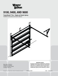
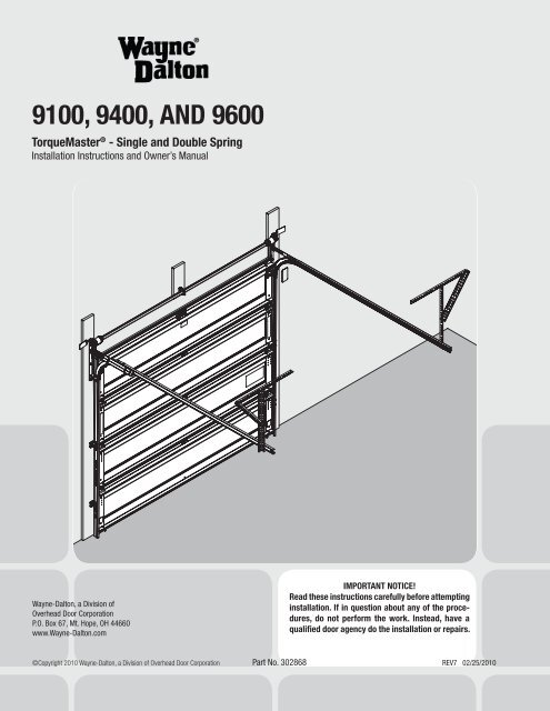
<strong>9100</strong>, <strong>9400</strong>, AND <strong>9600</strong><strong>TorqueMaster</strong> ® - Single and Double <strong>Spring</strong>Installation Instructions and Owner’s Manual<strong>Wayne</strong>-<strong>Dalton</strong>, a Division ofOverhead Door CorporationP.O. Box 67, Mt. Hope, OH 44660www.<strong>Wayne</strong>-<strong>Dalton</strong>.comIMPORTANT NOTICE!Read these instructions carefully before attemptinginstallation. If in question about any of the procedures,do not perform the work. Instead, have aqualified door agency do the installation or repairs.©Copyright 2010 <strong>Wayne</strong>-<strong>Dalton</strong>, a Division of Overhead Door Corporation Part No. 302868 REV7 02/25/2010
<strong>TorqueMaster</strong> ® - Single and Double <strong>Spring</strong>Installation Instructions and Owner’s ManualIMPORTANT NOTICE!Read these instructions carefully beforeattempting installation. If in question aboutany of the procedures, do not perform thework. Instead, have a qualified door agencydo the installation or repairs.Package ContentsNOTE: Depending on the door model, some parts listed will not be supplied if notnecessary. rear supports may or may not be included with your door.DOOR SectionS (as required)(2) Top Bracket Slide(1)<strong>TorqueMaster</strong> ® <strong>Spring</strong> tube(2) Fully Adjustable RH/LHFlagangle (as required)(2) Quick Install RH/LHFlagangle (as required)(2) Horizontal Track RH/LHasymmetrical u-bar(if included)U-Bar(if included)idrive ® Operator(sold separately)(2) Horizontal Angle(21-15/16” or 80”)(as required)right and left cabledrum assembliesright & leftDrum WrapsQ.I. Jamb Brackets(As Required)(1) operator bracket(2) Top Bracket Baseweather seal & nails(if included)(2) VerticalTrack RH/LHright & leftEnd Brackets36 Tooth Worm Gear(as required)Counter Covers(as required)Counter Gear(as required)Rollers(as required)(1) Center Bracketassembly<strong>9100</strong>, <strong>9600</strong>, 5120, 5140© Copyright 2005 <strong>Wayne</strong>-<strong>Dalton</strong> Corp. Part No. 302868 Rev. 2 08/04/2005MANUALstud plate(if included)lubricating oil(as required)pull rope(if included)(1) Loose Winding Shaft(SINGLE SPRING only)(1) 3/8” - 16 nylocknut (if included)1/4”- 20 Flanged HexNut (as required)(2) 3/8”- 16 Hex Nut5/16” x 1 5/8” Hex Head Lag Screw(as required)3/8”- 16 x 3/4” hex headbolt (if included)(2) 3/8”-16 x 3/4”Truss Head Bolt1/4”-20 x 11/16” Self DrillingScrew (as required)(4) 1/4”-20 x 9/16” largehead ribbed track bolts(4) 1/4”-20 x 5/8”Carriage Bolts1/4”-14 x 5/8” Self TappingScrew (as required)(2) #12 x 1/2” Phillipshead screws(2) #10 Phillipshead screwsPlease Do Not Return This Product To The Store. Contact your local <strong>Wayne</strong>-<strong>Dalton</strong> dealer. To find your local <strong>Wayne</strong>-<strong>Dalton</strong> dealer, refer to yourlocal yellow pages/business listings or go to the Find a Dealer section online at www.<strong>Wayne</strong>-<strong>Dalton</strong>.com3
Door Section IdentificationTools Needed:NOTE: This provides an alternative methodfor identifying your door sections/stackposition.Hinges are always pre-attached at the topof each section (except top section) andthe hinges are stamped for identification,#1, #2, #3, and #4 (#4 only on fivesection doors). See view below. Thestamp identifies the stacking sequenceof the section. The sequence is alwaysdetermined by #1 being the bottomsection to #3 or #4 being the highestintermediate section. See views to theright. If the stamp on the end hinge isillegible, refer to the section side viewillustration to the right.#3#2Warning labelTop SectionWarning labelIntermediate SectionYellow and blackwarning labelThe section side view illustration showsthe end hinge profile of all the sections,and can also be used in conjunction withidentifying each sections.#1Lock SectionThe bottom section can be identifiedby a #1 end hinge, the factory attachedbottom astragal, or by the bottom bracketwarning labels on each end stile.The lock section can be identified bya #2 end hinge. Some sections may havea yellow and black warning label on theright side of the section.The intermediate section can beidentified by a #3 end hinge. Somesections may have a warning labelattached to either the right or left of thesection.NOTE: #4 End hinges are used on thefourth section of five section doors.Astragal7/8”Bottom Bracketwarning LabelsBottom SectionSECTION side view1 1/8”1 3/8” 1 19/32”The top section can be identified withno pre-installed end or center hinges onthe section and the warning label attachedin the upper middle of the section.#1 endhinge#2 endhinge#3 endhinge#4 endhingeBOT.BOTTOMBRACKETLOCKINT.INT.(USED ONLYON FIVESECTIONS)Typical hinge stamping locationASTRAGAL4Please Do Not Return This Product To The Store. Contact your local <strong>Wayne</strong>-<strong>Dalton</strong> dealer. To find your local <strong>Wayne</strong>-<strong>Dalton</strong> dealer, refer to yourlocal yellow pages/business listings or go to the Find a Dealer section online at www.<strong>Wayne</strong>-<strong>Dalton</strong>.com
Tools RequiredPower Drill Ratchet Wrench Pliers/Wire CuttersTape Measure1/8”, 3/16” Drill BitsPRE-INSTALLATIONPhillips Head ScrewdriverFlat Tip ScrewdriverPencilNeedle Nose PliersGloves7/16”, 1/2”, 9/16”Sockets7/16” Socket Driver3/8”, 7/16”, 1/2”, 9/16”WrenchesSafety GlassesStep LadderHammervice gripsVice clamps(2) Saw HorsesWARNINGRemoving An Old DoorIf your counterbalance system is other than those mentioned, do not attempt to work on it, buthave a qualified door agency perform the work. Otherwise, severe or fatal injury could result.WARNINGDisconnect and remove any electric opener prior to removal of counterbalance systems toprevent unintended door operation. Otherwise, severe or fatal injury could result.WARNINGCounterbalance spring tension must be relieved before removing any hardware. A powerfulspring releasing it’s energy suddenly can cause severe or fatal injury.WARNINGIf you have back problems do not attempt this, or severe injury could resultWARNINGRemoving an existing door can be dangerous. Follow instructions on pages 6-10 “removing an olddoor/preparing the opening” carefully, otherwise, severe or fatal injury could result.If you have an existing door, follow the instructions to identify which counterbalance removal is necessary. The process of removingan existing door begins by identifying it’s counterbalance system. If you are not removing an existing door, proceed to Preparing TheOpening on page 10. Generally, you will find three (3) types of counterbalance systems: extension <strong>Spring</strong>, <strong>Wayne</strong>-<strong>Dalton</strong> ® exclusive<strong>TorqueMaster</strong> ® and Torsion spring counterbalance systems.For more technical information regarding the opening preparation, installation and use of your garage door and opener, you can go towww.dasma.com and click on Publications and then Technical Data Sheet.Please Do Not Return This Product To The Store. Contact your local <strong>Wayne</strong>-<strong>Dalton</strong> dealer. To find your local <strong>Wayne</strong>-<strong>Dalton</strong> dealer, refer to yourlocal yellow pages/business listings or go to the Find a Dealer section online at www.<strong>Wayne</strong>-<strong>Dalton</strong>.com5
P1Tools Needed:ApprovedWinding Bars3/8” WrenchVice ClampRecommendedtools frompage 5Torsion <strong>Spring</strong> RemovalFor Standard LiftWARNINGFailure to use approvedwinding bars can causespring energy to be releasedsuddenly, resulting in severeor fatal injury.WARNINGCOUNTERBALANCE SPRINGTENSION MUST BE RELIEVEDBEFORE REMOVING ANYHARDWARE. A POWERFULSPRING RELEASING IT’S ENERGYSUDDENLY CAN CAUSE SEVERE ORFATAL INJURY.Do not release the torsion spring tensionunless you are qualified and experienceddoor technician, but have a professionaldoor agency release the tension.Step 1: Close the door and place viceclamps to the back legs on both verticaltracks, above the third roller to preventthe door from lifting as you unwind thesprings. Use only approved winding barsavailable from your dealer. Do not useundersized steel rods, screw drivers oranything else to unwind the springs.Position the ladder just off to the sideof the winding cone. The winding coneshould be easy to reach without puttingyour body directly in front of it.Step 2: Insert a winding bar into oneof the holes in the winding cone. Exertupward pressure. Using caution, loosenthe two (2) set screws in the windingcone. Be prepared to support the fulltorsional force of the spring when the setscrews are loosened.Step 3: Once set screws are loose, slowlyand carefully lower the winding rod until itrests against the door. Insert other windingbar into the upper hole. Push up andremove lower bar. Carefully lower upperwinding bar until it rests against the door.Repeat process until all tension is relieved.If your door is equipped with two (2)torsion springs, follow the same procedureto relieve tension on the second spring.Step 4: Remove vice clamps from tracks,unbolt torsion shaft assembly and removefrom work area.NOTE: Continue with “P4” on page 9 aftercompleting this step.APPROVED WINDING BARWINDING CONESET SCREWSTORSION ASSEMBLYfirmly hold winding bars andcautiously loosen set screws6Please Do Not Return This Product To The Store. Contact your local <strong>Wayne</strong>-<strong>Dalton</strong> dealer. To find your local <strong>Wayne</strong>-<strong>Dalton</strong> dealer, refer to yourlocal yellow pages/business listings or go to the Find a Dealer section online at www.<strong>Wayne</strong>-<strong>Dalton</strong>.com
P2<strong>TorqueMaster</strong> ® <strong>Spring</strong> Removalloosen locknut 1/4 turncountergear/ coverTools Needed:Recommendedtools frompage 5A <strong>TorqueMaster</strong> ® spring system can beidentified by the end brackets. For singlespring applications, the right hand endbracket will always have a drive gear,counter gear, counter cover, and a windingbolt head. The left hand end bracket willhave no gears, counter cover, or windingbolt head. The hole for the winding bolthead will be plugged.For double springs, both the right handand left hand end brackets will alwayshave a drive gear, counter gear, countercover and a winding bolt head.IMPORTANT: Right and left hand isalways determined from inside thebuilding looking out.Step 1: If you have a black counter cover:Place a mark on the drive gear tooth and anadjacent mark on the right hand end bracket(Fig. 1). Loosen the lock nut 1/4 turn using a7/16” wrench and continue with Step 2.If you have a gray counter cover: Loosenthe lock nut 1/4 turn using a 7/16” wrenchand continue with Step 2.Step 2: Using an electric drill (Hightorque / gear reduced to 1300 rpmpreferred) with a 7/16” hex head driver,unwind the right hand winding bolt headcounterclockwise (Fig. 2) and count thenumber of turns the mark on the drivegear passes the adjacent mark on the endbracket. Referencing the chart below, bydoor height, stop unwinding the springonce the counted turns have reached thelisted number of turns.6’-0” Door Height = 14 turns6’-3” Door Height = 14 1/2 turns6’-5” Door Height = 15 turns6’-6” Door Height = 15 turns6’-8” Door Height = 15 1/2 turns6’-9” Door Height = 15 1/2 turns7’-0” Door Height = 16 turns7’-3” Door Height = 16 1/2 turns7’-6” Door Height = 17 turns7’-9” Door Height = 17 1/2 turns8’-0” Door Height = 18 turnsFig. 1right handend bracketplace mark on end bracketand drive gear toothbefore unwinding springsPRE-INSTALLATIONend bracketright handwinding bolt headelectric drillwith 7/16” hexdriver (do notuse impactgun)CAUTION: DO NOT USE IMPACT GUN TOUNWIND SPRINGS.IMPORTANT: DO NOT reference thecounter cover when counting thenumber of turns being unwoundon the spring, but follow theinstructions above.Step 3: Verify that spring tension has beenreleased by pulling the counterbalancecable on the right hand cable drum awayfrom the header (Fig. 3). If spring tensionhas been released, the cable will be loose.In addition, the <strong>TorqueMaster</strong> ®right handcable drum<strong>TorqueMaster</strong> ®<strong>Spring</strong> TubeFig. 2Fig. 3check cabletensioncountergearcountercoverpry counter gearand counter coverfrom end bracketusing flat TipscrewdriverFig. 4Please Do Not Return This Product To The Store. Contact your local <strong>Wayne</strong>-<strong>Dalton</strong> dealer. To find your local <strong>Wayne</strong>-<strong>Dalton</strong> dealer, refer to yourlocal yellow pages/business listings or go to the Find a Dealer section online at www.<strong>Wayne</strong>-<strong>Dalton</strong>.com7
<strong>TorqueMaster</strong> ® <strong>Spring</strong>Removal continued...8Tools Needed:Recommendedtools frompage 5<strong>Spring</strong> tube should be free to rotate ineither direction. If the counterbalancecable is still taut and the <strong>TorqueMaster</strong> ®spring tube is difficult to rotate, that is anindication that spring tension still existson the left hand spring. Repeat Steps 1and 2 for releasing spring tension on theleft hand side.Step 4: Using a flat tip screwdriver, prythe counter gear and counter coverfrom the right hand end bracket (Fig. 4on previous page). Discard the countergear and counter cover. On double springapplications, repeat for left hand side.Step 5: Remove the upper 5/16” x1-5/8” lag screw from the right hand endbracket (Fig. 5). Attach locking pliers tothe upper portion of the end bracket andhold the housing steady while removingthe lower 5/16” x 1-5/8” lag screw and#10 x 1/2” phillips head screw from theend bracket (Fig. 6).Step 6: Holding the right hand endbracket steady with locking pliers,carefully pry the end bracket and drivegear off the winding shaft using a flat tipscrewdriver (Fig. 7).CAUTION: THE WINDING SHAFT MAYROTATE WHEN REMOVING THE ENDBRACKET AND DRIVE GEAR.Step 7: Repeat Step 4 for the left handside. Holding the left hand end bracketsteady with locking pliers, carefully prythe end bracket off the winding shaftusing a flat tip screwdriver (Fig. 7).Step 8: Remove the two (2) lag boltsattaching the center bracket assembly tothe header board (Fig. 8).Step 9: Lift the right hand side of the<strong>TorqueMaster</strong> ® spring tube and slide thecable drum off. Realign the groove in thewinding shaft with the radial notch in theflagangle and drape the counterbalancecable with drum over the flagangle. Liftthe left hand side of the <strong>TorqueMaster</strong> ®spring tube and slide the cable drumand winding shaft off (Fig. 9). Drape thecounterbalance cable with drum over theflagangle. Lift the <strong>TorqueMaster</strong> ® springassembly off the flagangles and out ofthe doorway. Unhook the counterbalancecables from the bottom brackets andremove all parts from the work area.NOTE: The cable drums may be difficult toremove. If so, twist the cable drum to aidin removal.NOTE: Continue with “P4” on page 9 aftercompleting this step.remove toplag screwremovebottom lagscrewCENTERBRACKETASSEMBLY(2) 5/16” x 1-5/8”hex head lagscrewsPlease Do Not Return This Product To The Store. Contact your local <strong>Wayne</strong>-<strong>Dalton</strong> dealer. To find your local <strong>Wayne</strong>-<strong>Dalton</strong> dealer, refer to yourlocal yellow pages/business listings or go to the Find a Dealer section online at www.<strong>Wayne</strong>-<strong>Dalton</strong>.comFig. 8Fig. 5use locking pliersto hold end bracketFig. 6Fig. 7remove cable drum andwinding shaftremove #10phillipshead screwhold theend bracketsteady withlocking plierspry end bracket from windingshaft using a flat tip screwdriver and locking pliersdrape cableacrosstop offlaganglelift<strong>TorqueMaster</strong> ®<strong>Spring</strong> Tubeoff flagangleFig. 9
P3Tools Needed:Recommendedtools frompage 5Extension <strong>Spring</strong> RemovalStep 1: Raise the door to the fully openposition and place vice clamps to the backlegs of both vertical tracks, below thebottom rollers to prevent the door fromfalling. By opening the door you releasemost of the spring tension. Carefullyunfasten the S-hook from the horizontalangle. Remove cable, sheave and extensionspring. Repeat for the other side. If safetycables are running through the extensionsprings, remove them also. Remove partsfrom work area.remove lag screwfrom safety cable (ifinstalled). repeat foropposite side.bottom section(door open)PRE-INSTALLATIONStep 2: Holding door in the open position,remove the vice clamps, be preparedto support the entire weight of the door.Garage doors can weigh 200-400 pounds.With assistance, carefully lower the door, bygrasping the door firmly by it’s lift handles.Do not place fingers or hands near joints,between sections, or between bottom ofdoor and floor. Otherwise, severe injurycould result.carefully remove “s”hook and countrebalancecable (repeat for theopposite side)horizontal angleNOTE: Continue with “P4” on page 9 aftercompleting this step.P4Removing the Old DoorTools Needed:Recommendedtools frompage 5Having removed the counterbalancesystem, the door can now bedisassembled.Start by first removing the top row ofcenter hinge(s).top brackethorizontal trackWith assistance, hold the top section tokeep it from falling and remove thetop brackets. With assistance, lift the topsection out of the opening and removeit from the work area. Repeat for allremaining sections.hingesAfter door is disassembled, unbolt bothtrack assemblies from the jambs andremove all material from the work area.You can neatly dispose of the old door byplacing it in the carton of your new door.Clean up area and complete “Preparingthe Opening” “P5” on page 10 beforeinstalling the new door.Please Do Not Return This Product To The Store. Contact your local <strong>Wayne</strong>-<strong>Dalton</strong> dealer. To find your local <strong>Wayne</strong>-<strong>Dalton</strong> dealer, refer to yourlocal yellow pages/business listings or go to the Find a Dealer section online at www.<strong>Wayne</strong>-<strong>Dalton</strong>.com9
P5Tools Needed:Recommendedtools frompage 5Preparing the OpeningWARNINGFailure to securelyattach a suitablemounting pad to structurally soundframing could cause springs to violentlypull mounting pad from wall, resultingin severe or fatal injury.If you just removed your existing door or you are installing a newdoor, complete all steps in preparing the opening.For detailed technical information regarding the openingpreparation, refer to the DASMA Technical Data Sheet TDS #161Connecting Garage Door Jambs to Building. Framing located atwww.dasma.com.header board2” x 6” lumberpreferredplumb jambslevel headerdoorwidthsuitable mountingsurface 2” x 6”lumber minimumdoorheightThe inside of your garage door opening should be framed withwood jambs and header. It is recommended that 2” x 6” lumberbe used. The jambs must be plumb and the header level. Thejambs should extend a minimum of 12” (305 mm) above thetop of the opening for <strong>TorqueMaster</strong> ® counterbalance systems.For low headroom applications, the jambs should extend tothe ceiling height. Minimum side clearance required, from theopening to the wall, is 3-1/2”.headerheadroombackroomIMPORTANT: Closely inspect jambs, header and mountingsurface. Any wood found not to be sound, must bereplaced.The jambs and header must be securely fastened to soundframing members. Do not place jambs and header over drywall,paneling, etc. Heads of fasteners must be flush or below jamband header surface, so they do not interfere with installation oroperation of new door.WEATHER SEALjamb<strong>TorqueMaster</strong> ® counterbalance systems, a suitable mountingsurface must be firmly attached to the wall, above the header atthe center of the opening.The mounting surface must be 2” x 6” lumber minimum (Selectsouthern yellow pine lumber. Do not use lumber marked asspruce-pine-fur or SPF).jambjambWeatherseal10The mounting surface must be securely attached to block orconcrete wall with four (4) 3/8” masonry anchors or four (4)5/16” x 4” lag screws for a wood structure.NOTE: Drill a 3/16” pilot hole in the mounting surface to avoidsplitting the lumber. Do not attach the mounting surface withnails.Weather seal: Fit weather seal (may not be included) to fit thejambs and header. Align the edge of the weather seals an 1/8” to1/4” inside the edge of the opening. Temporarily nail the weatherseal to the jambs to keep the bottom section from falling out ofthe opening during installation. Space nails approximately 12”apart.NOTE: Do not permanently attach weather seal to the jambs atthis time. Permanent installation will be done in Step 34.HEADROOM REQUIREMENT: Headroom is defined as the spaceneeded above the top of the door for tracks, springs, etc. to allowthe door to open properly. If the door is to be motor operated,2-1/2” (64 mm) of additional headroom is required.NOTE: 6” LHR Conversion Kit is available for 12” Radius only.Contact your local <strong>Wayne</strong>-<strong>Dalton</strong> ® dealer.BACKROOM REQUIREMENT: Backroom is defined as thedistance needed from the opening back into the garage to allowthe door to open fully.Headroom requirementTRACK TYPE <strong>TorqueMaster</strong> ®15” Radius track 11-3/4” (299 mm)12” Radius track 10-1/2” (267 mm)6” LHR Kit † 6” (152 mm)Backroom requirementMANUALDOOR HEIGHT TRACKLIFT98”6’5”, 6’6”, 7’0” 12”, 15” Radius(2489 mm)7’6”, 8’0” 12”, 15” RadiusQuick Install Track110”(2794 mm)MOTOROPERATED120”(3048 mm)132”(3353 mm)Please Do Not Return This Product To The Store. Contact your local <strong>Wayne</strong>-<strong>Dalton</strong> dealer. To find your local <strong>Wayne</strong>-<strong>Dalton</strong> dealer, refer to yourlocal yellow pages/business listings or go to the Find a Dealer section online at www.<strong>Wayne</strong>-<strong>Dalton</strong>.com
InstallationIMPORTANT: Read instructions titled “p4” “Removing the old door” on page 9 and “p5” “PREPARING THE OPENING” onpage 10 before attempting door installation.IMPORTANT: Stainless steel or PT2000 coated lag screws MUST be used when installing center bearing brackets,end brackets, jamb brackets, operator mounting/support brackets and disconnect brackets on treated lumber(preservative-treated). Stainless steel lag screws are NOT necessary when installing products on un-treatedlumber.NOTE: It is recommended that 5/16” x 1-5/8” lag screws be pilot drilled using a 3/16” drill bit, and 1/4” x 2” lag screws and1/4” x 1-1/2” lag screws be pilot drilled using a 1/8” drill bit, prior to fastening.NOTE: If you have riveted track, skip these steps, 1 through 2 and proceed to step3.INSTALLATION1Attaching Quick Install FlagAngle to Vertical TrackQUICK INSTALL TAB UNLOCKEDQUICK INSTALL TAB LOCKEDTools Needed:NoneNOTE: If you have fully adjustableflagangle, skip this step and completeStep 2.Place the lower quick install tab of theflagangle in the quick install feature ofthe vertical track. Give the flagangle 1/4turn to lock in place. Repeat for otherside.FLAGANGLEFLAGANGLENOTE: After completing this step,continue with Step 3.VERTICALTRACKVERTICALTRACKleft hand track and flagangle right hand track and flagangle11Please Do Not Return This Product To The Store. Contact your local <strong>Wayne</strong>-<strong>Dalton</strong> dealer. To find your local <strong>Wayne</strong>-<strong>Dalton</strong> dealer, refer to yourlocal yellow pages/business listings or go to the Find a Dealer section online at www.<strong>Wayne</strong>-<strong>Dalton</strong>.com
2Attaching Fully AdjustableFlagangle to Vertical TrackFully Adjustable flagangleTools Needed:NoneNOTE: If quick install flagangle wasinstalled in Step 1, skip this step andcontinue with Step 3. If not, completethis step.Hand tighten the flagangle to the verticaltrack using (2) 1/4” - 20 x 9/16” largehead ribbed track bolts (or stud plate ifincluded) and (2) 1/4” - 20 flange hexnuts.1/4”- 20flange hexnuts1/4” - 20 x 9/16”large head ribbedTrack BoltsSecure the flange nuts after flaganglespacing is complete (Step 13).veritcal trackstud plate3Horizontal AngleholetabsHOrizontalAnglekey slotTools Needed:HammerPosition the horizontal angle as shown.Place tabs of horizontal angle in the keyslot of horizontal track. Using a hammer,tap the horizontal angle towards thecurved end of the track until the hole intrack and angle are aligned. Set tracksaside.NOTE: For larger doors, a full lengthhorizontal angle may or may not bespot welded to the horizontal track. Ifthe horizontal angle is not welded, thehorizontal angle will be installed asshown.NOTE: If you have riveted track, skipthese step 4 and proceed to step 5.Horizontal Anglehorizontal TRACKhorizontalTRACKholehorizontalTRACKhorizontalanglehorizontalTRACK12Please Do Not Return This Product To The Store. Contact your local <strong>Wayne</strong>-<strong>Dalton</strong> dealer. To find your local <strong>Wayne</strong>-<strong>Dalton</strong> dealer, refer to yourlocal yellow pages/business listings or go to the Find a Dealer section online at www.<strong>Wayne</strong>-<strong>Dalton</strong>.comtabs
4Tools Needed:NoneInstalling Q.I. Jamb BracketsMeasure the length of the vertical tracks.Using the jamb bracket schedule,determine the placement of the jambbrackets for your door height and tracktype. To install the jamb brackets,align the twistlock tab on the quickinstall jamb bracket with the quickinstall feature in the track and turn thebracket perpendicular to the track so themounting flange is toward the back (flat)leg of the track.DOORHEIGHTJAMB BRACKET SCHEDULE1ST SET 2ND SET 3RD SETJAMB BKT POSITION JAMB BKT POSITION JAMB BKT POSITIONleft side showntwistlock tabright side shown3rd SET HOLES6’0” 64” TRACK(1626 mm)QIJB - 5 MIDDLE QIJB - 6 BOTTOM NOT APPLICABLE6’5” 69” TRACK(1753 mm)6’8” 72” TRACK(1829 mm)7’0” 76” TRACK(1930 mm)7’3” 79” TRACK(2007 mm)7’6” 82” TRACK(2083 mm)QIJB - 3 BOTTOM QIJB - 6 MIDDLE NOT APPLICABLEQIJB - 3 BOTTOM QIJB - 6 MIDDLE NOT APPLICABLEQIJB - 3 BOTTOM QIJB - 7 TOP NOT APPLICABLEQIJB - 3 BOTTOM QIJB - 5 BOTTOM QIJB - 6 BOTTOMQIJB - 3 BOTTOM QIJB - 5 BOTTOM QIJB - 6 BOTTOMQI jamb bracketTopholeMiddlehole2nd SET HOLES1st SET HOLESINSTALLATION7’9” 85” TRACK(2159 mm)8’0” 4 SECTIONS88” TRACK (2235 mm)QIJB - 3 BOTTOM QIJB - 5 BOTTOM QIJB - 6 BOTTOMQIJB - 3 MIDDLE QIJB - 6 TOP QIJB - 7 MIDDLEBottomhole8’0” 5 SECTIONS88” TRACK (2235)QIJB - 3 BOTTOM QIJB - 7 TOP QIJB - 8 TOPquick install feature5DrumsLeft Hand TORQUEMASTER ®counterbalance DRUM#1 End Hinge(hinge tube)Tools Needed:NoneIMPORTANT: Right and left hand isalways determined from inside thebuilding looking out.NOTE: For door section identification seepage 4.<strong>TorqueMaster</strong> ® counterbalance drumsare marked right and left hand. Uncoil thecounterbalance cables and make sure youplace the right hand cable loop on the righthand milford pin and place the left handcable loop on the left hand milford pin.Insert a roller into bottom bracket of thebottom section and insert another rollerat #1 end hinge at the top of the bottomsection. Repeat for other side.NOTE: Verify astragal (bottom seal) isaligned with door section. If there is morethan 1/2” excess astragal on either side,trim astragal even with door section.astragalCounterbalancecableMILFORD PINBOTTOMSECTIONRollersBOTTOMSECTIONBOTTOMSECTIONbottom bracketPlease Do Not Return This Product To The Store. Contact your local <strong>Wayne</strong>-<strong>Dalton</strong> dealer. To find your local <strong>Wayne</strong>-<strong>Dalton</strong> dealer, refer to yourlocal yellow pages/business listings or go to the Find a Dealer section online at www.<strong>Wayne</strong>-<strong>Dalton</strong>.com13
6Tools Needed:LevelBottom SectionBefore installing the bottom section,the weather seal (may not be included)must be installed (see Preparing theOpening on page 10)Center the bottom section in the dooropening. Level section using woodenshims (if necessary) under the bottomsection.weather sealdoor openinglevelBOTTOM SECTIONwooden shims(if necessary)7Vertical Trackcable drumfLAGANGLEvertical trackBOTTOM SECTIONTools Needed:3/16” Drill BitPower Drill7/16” SocketDriverTape MeasureLevelIMPORTANT: The tops of thevertical tracks must be levelfrom side to side. If the bottomsection was shimmed to level it.The vertical track on the shimmedside, must be raised the height ofthe shim.Position the left hand vertical trackassembly over the rollers of the bottomsection. Make sure the counterbalancecable is located between the rollersand the door jamb. Drill 3/16” pilotholes for the lag screws. Loosely fastenjamb brackets and flagangle to thejamb using 5/16” x 1-5/8” lag screws.Tighten lag screw securing bottomjamb bracket to jamb, to maintain5/8” spacing. Hang cable drum overflagangle. Repeat for the right handside.CABLEJAMBBRACKET5/16” x 1-5/8”LAG SCREWSVERTICALTRACKASSEMBLYBOTTOM SECTIONrollerLAGSCREWlocations5/8”12r qi flagangleLAGSCREWlocationsLAGSCREWlocations15r qi flaganglequick installjamb bracket1412r & 15r FullyAdjustable flaganglelagscrewPlease Do Not Return This Product To The Store. Contact your local <strong>Wayne</strong>-<strong>Dalton</strong> dealer. To find your local <strong>Wayne</strong>-<strong>Dalton</strong> dealer, refer to yourlocal yellow pages/business listings or go to the Find a Dealer section online at www.<strong>Wayne</strong>-<strong>Dalton</strong>.com
8Tools Needed:Power Drill7/16” SocketDriverStacking SectionsNOTE: For door section identification seepage 4.NOTE: Make sure hinges are flipped down,when stacking another section on top.Place rollers in hinge tubes of the secondsection (lock section). With assistance,lift second section and guide rollers intothe vertical tracks. Keep sections alignedand fasten hinges to connect the sectionsusing 1/4”-14 x 5/8” self tapping screws.Repeat for other section(s) except topsection.LOCK SECTIONIMPORTANT: Push & hold the hingeleaf against section while securingwith 1/4”-14 x 5/8” self tappingscrews. End Hinges have (2) screwsand Intermediate hinges have (3)screws.NOTE: Install lock at this time (soldseparately) see instructions in OPTIONALSIDELOCK INSTALLATION on page 32.(2) 1/4”-14 X 5/8”SELF TAPPING SCREWSend hinges (left hand shown, righthinge symmetrically opposite)(3) 1/4”-14 X 5/8” SELF TAPPINGSCREWSintermediate hingesINSTALLATION9Tools Needed:Power Drill7/16” SocketDriverTop BracketsTo install the L-shaped top brackets,align the top holes in the top bracketbase with the second set of holes in theendcap.Fasten using (4) 1/4” - 14 x 5/8” selftapping screws. Secure the top bracketslide to the bracket base loosely using(2) 1/4” - 20 x 5/8” carriage bolts and(2) 1/4” - 20 flanged hex nuts. Thebracket will be tightened and adjustedin Step 16. Insert rollers into top bracketslide. Repeat for other side.1st SetTOP SECTION2nd setTOP BRACKET BASETOP BRACKET SLIDETOP SECTION(4) 1/4” - 14 x 5/8”SELF TAPPINGSCREWS(2) 1/4” - 20 x 5/8”CARRIAGE BOLTS(2) 1/4” - 20FLANGED HEXNUTSROLLERTOP SECTIONTOP BRACKET SLIDEPlease Do Not Return This Product To The Store. Contact your local <strong>Wayne</strong>-<strong>Dalton</strong> dealer. To find your local <strong>Wayne</strong>-<strong>Dalton</strong> dealer, refer to yourlocal yellow pages/business listings or go to the Find a Dealer section online at www.<strong>Wayne</strong>-<strong>Dalton</strong>.com15
10U-Baroperator bracket(installed in the step 12)6”6”Tools Needed:Power Drill7/16” SocketDriver(2) Saw HorsesNOTE: If you have a model <strong>9400</strong>/<strong>9600</strong>Series door with windows in the topsection or <strong>9100</strong> Sonoma (8’ high), skipthis step and complete Step 11.NOTE: Model <strong>9100</strong> Series door over 13’wide require a 3” U-Bar (supplied).Place the 3” u-bar over the top rib.Fasten each end of the u-bar to theendcap with (2) 1/4”- 20 x 11/16” selfdrilling screws.(2) 1/4”-20 x 11/16”SELF DRILLING SCREWSU-Bartop door section(2) 1/4”-20 x 5/8”SELF tappingSCREWSFasten center of the u-bar as shownto the rib using (2) 1/4”-20 x 5/8” selftapping screws one 6” to the left and one6” to the right of the center of the doorsection.NOTE: After completing this step,continue with Step 12.attaching center of u-Barattaching ends of u-Bar11Tools Needed:Power DrillU-Bar - AsymmetricalNOTE: If a 3” U-Bar was installed in Step10, skip this step.30” to 36”operator bracket(installed in the step 12)6”6”7/16” SocketDriverNOTE: Model <strong>9400</strong>/<strong>9600</strong> glazed topdoors 13’-0” wide or greater will besupplied with a 3” asymmetrical u-barfor the top section.Place the 3” asymmetrical u-bar over thetop rib. Fasten each end of the u-bar tothe endcap with (2) 1/4”- 20 x 11/16”self drilling screws.U-Bar(2) 1/4”-20 x 5/8” SelfTapping screws(2) 1/4”-20 x 11/16”SELF DRILLINGSCREWStop door section(2) 1/4”-20 x 5/8”SELF tappingSCREWSFasten center of the u-bar as shownto the rib using (2) 1/4”-20 x 5/8” selftapping screws 6” off of the center of thedoor section.Fasten both walls of the u-bar asshown using (2) 1/4”-20 x 5/8” selftapping screws every 30-36 inches.(Approximately 18 self tapping screwsper 18’ u-bar)16attaching center of u-Barattaching intermediates of u-BarPlease Do Not Return This Product To The Store. Contact your local <strong>Wayne</strong>-<strong>Dalton</strong> dealer. To find your local <strong>Wayne</strong>-<strong>Dalton</strong> dealer, refer to yourlocal yellow pages/business listings or go to the Find a Dealer section online at www.<strong>Wayne</strong>-<strong>Dalton</strong>.com
12Tools Needed:Power Drill7/16” SocketDriverVice ClampsPhillips HeadScrewdriverOperator BracketNOTE: Operator bracket must bemounted and secured prior to installingtop section.IMPORTANT: When installing atrolley type operator on <strong>9100</strong>,<strong>9400</strong>, and <strong>9600</strong> Series doors, a<strong>Wayne</strong>-<strong>Dalton</strong> trolley bracketmust be securely attached tothe top section, along with anyu-bar’s initially provided with thedoor. It is then unnecessary tofurther reinforce the top sectionof the above model <strong>Wayne</strong>-<strong>Dalton</strong>door, when attaching a trolleytype operator, as long as theinstallation of the operatoris according to Installationinstructions and owner’s manualand force settings are adjustedproperly.Prior to installing top section, locate thecenter of the top section and seat theoperator bracket on male part of the topsection. For retro fit applications, theoperator bracket must be aligned withan existing operator and positioned ontop section so it bridges the transitionpoint of the section thickness, as shownin FIG. 1.1 and 1.2. Install (2) #12 x 1/2”phillips head screws on the oppositeside of operator bracket, as shown inFIG. 1.3. Clamp operator bracket to u-bar(if furnished), as shown in FIG. 1.4. Firstattach (4) 1/4” - 14 x 5/8” self-tappingscrews to the operator bracket, asshown in FIG. 1.5. Then attach (2) 1/4”- 14 x 5/8” self-tapping screws to theoperator bracket, as shown in FIG. 1.6.Remove vice clamps.NOTE: If you have a <strong>9100</strong> door, (2) of the1/4” - 20 x 11/16” self-drilling screwsused to attach the u-bar instead of (2)1/4” - 14 x 5/8” self-tapping screwswhen attaching operator bracket to u-bar, as shown in FIG. 1.6.NOTE: When attaching operatorbracket to top section with u-bar, applyadditional pressure to thread into theu-bar.NOTE: See FIG. 1.7 for installing operatorbracket on top section without u-bars.Align center of both tabs withcenter line of top sectionTopsectionWith orwithoutU-barFIG. 1.1Opposite side ofOperator bracketFIG. 1.3(4) 1/4” - 14 x 5/8”self-tappingscrewsFIG. 1.5OperatorBracket(2) #12 x 1/2”Phillips headscrewsOperatorbracketMale part oftop sectionOperatorBracketTopsectionFIG. 1.2Please Do Not Return This Product To The Store. Contact your local <strong>Wayne</strong>-<strong>Dalton</strong> dealer. To find your local <strong>Wayne</strong>-<strong>Dalton</strong> dealer, refer to yourlocal yellow pages/business listings or go to the Find a Dealer section online at www.<strong>Wayne</strong>-<strong>Dalton</strong>.comU-barFIG. 1.7U-barU-barOperator BracketVice clampNOTE: not requiredfor j-struts.FIG. 1.4(2) 1/4” - 14 x 5/8”self-tappingscrewsU-bar(2) 1/4” - 20 x 11/16”self-DRILLING screwsFIG. 1.6(6) 1/4” - 14 x 5/8”Self-tappingscrewsOperatorbracketOperatorbracket17INSTALLATION
13Top SectionNAILdoor width+3-3/8” to 3-1/2”Tools Needed:HammerPlace the top section in the openingand vertically align with lower sections.Temporarily secure the top section bydriving a nail in the header near thecenter of the door and bending it over thetop section. Now flip up hinge leaf, holdtight against section, and fasten centerhinges first, and end hinges last. (Referto Step 8). When installing a door with a<strong>TorqueMaster</strong> ® counterbalance system,vertical track alignment is critical.Position flagangle between 1-11/16” (43mm) to 1-3/4” (44 mm) from the edgeof the door. Flagangles must be parallelto the door sections. Now complete thevertical track installation by securing thecenter jamb bracket and tightening theother lag screws. Repeat for other side.1-11/16”TO 1-3/4”IMPORTANT: The dimension betweenthe flagangles must be doorwidthplus 3-3/8” (86 mm) to 3-1/2”(89 mm) for smooth, safe dooroperation.FLAGANGLEtopSECTION1814Tools Needed:9/16” SocketRatchet Wrench9/16” WrenchLevelAttaching Quick Install Flagangleto Horizontal TrackNOTE: If you have fully adjustable flagangle,skip this step and complete Step 15.To install horizontal track, place the curvedend over the top roller. Align key slot of thehorizontal track with the quick install tabof the flagangle. Push curved portion ofhorizontal track down to lock in place.WARNINGDO NOT RAISE DOOR UNTIL HORIZONTALTRACKS ARE SE CURED AT REAR, ASOUTLINED IN Step 34, OR DOOR COULDFALL FROM OVERHEAD POSI TION CAUSINGSEVERE OR FATAL INJURY.Level the horizontal track assembly andbolt the horizontal angle to the slot in theflagangle using (1) 3/8” - 16 x 3/4” trusshead bolt and (1) 3/8” - 16 hex nut. Repeatfor other side. Remove the nail that wastemporarily holding the top section in place,installed in Step 13.IMPORTANT: Failure to remove nailbefore attempting to raise doorcould cause permanent damage totop section.NOTE: If an idrive ® opener will be installed,position horizontal tracks slightly above level.NOTE: After completing this step, continuewith Step 16.horizontaltrackQUICKINSTALLTABverticaltrackPlease Do Not Return This Product To The Store. Contact your local <strong>Wayne</strong>-<strong>Dalton</strong> dealer. To find your local <strong>Wayne</strong>-<strong>Dalton</strong> dealer, refer to yourlocal yellow pages/business listings or go to the Find a Dealer section online at www.<strong>Wayne</strong>-<strong>Dalton</strong>.comkeyslot3/8” - 16 X 3/4”TRUSS HEAD BOLTflaganglehorizontaltrackkey slotverticaltrackQUICKINSTALLTAB3/8” - 16 Hex nutHORIZONTAL TRACKflaganglehorizontal ANGLE
15Tools Needed:7/16” Socket9/16” SocketRatchet Wrench9/16” WrenchLevelFlat TipScrewdriverAttaching Adjustable Flagangleto Horizontal TrackNOTE: If quick install flagangles wereinstalled in Step 14, skip this step andcontinue with Step 16. If not, complete thisstep.To install horizontal track, place the curvedend over the top roller. Align the bottom ofthe horizontal track with the vertical track.Hand tighten the horizontal track to theflagangle with (2) 1/4” - 20 x 9/16” largehead ribbed track bolts (or stud plate ifincluded) and (2) 1/4”-20 flange hex nuts.WARNINGDO NOT RAISE DOOR UNTIL HORIZONTALTRACKS ARE SE CURED AT REAR, ASOUTLINED IN STEP 34, OR DOOR COULDFALL FROM OVERHEAD POSI TION CAUSINGSEVERE OR FATAL INJURY.Level the horizontal track assembly andbolt the horizontal angle to the slot in theflagangle using (1) 3/8” - 16 x 3/4” trusshead bolt and (1) 3/8” - 16 hex nut. Repeatfor other side. Remove the nail that wastemporarily holding the top section inplace, installed in Step 13.IMPORTANT: Failure to remove nailbefore attempting to raise doorcould cause permanent damage totop section.NOTE: If an idrive ® opener will be installed,position horizontal tracks slightly abovelevel.1/4”-20 flangehex nutsflagangle 1/4” - 20 X 9/16”large headribbed trackbolts3/8” - 16 X 3/4”TRUSS HEAD BOLTstud plate3/8” - 16 Hex nuthorizontal ANGLEHORIZONTAL TRACKINSTALLATION16Tools Needed:7/16” WrenchAdjusting Top BracketsWith horizontal tracks installed, you cannow adjust the top brackets.topsectionHORIZONTALtrackVertically align the top section of thedoor with the lower sections. Oncealigned, position the top bracket slide,out against the horizontal track.Maintaining the slide’s position, tightenthe (2) 1/4” - 20 flange hex nuts tosecure the top roller slide to the topbracket base.CorrecttopsectiontopSECTIONTOPBRACKETSLIDE(2) 1/4” - 20FLANGE HEXNUTSinCorrectPlease Do Not Return This Product To The Store. Contact your local <strong>Wayne</strong>-<strong>Dalton</strong> dealer. To find your local <strong>Wayne</strong>-<strong>Dalton</strong> dealer, refer to yourlocal yellow pages/business listings or go to the Find a Dealer section online at www.<strong>Wayne</strong>-<strong>Dalton</strong>.com19
17Tools Needed:None<strong>TorqueMaster</strong> ® <strong>Spring</strong> Tube<strong>TorqueMaster</strong> ® springs come lubricatedand pre-assembled inside the<strong>TorqueMaster</strong> ® spring tube. To install, laythe <strong>TorqueMaster</strong> ® spring tube on thefloor (inside garage) in front of the doorwith the labeled end to the left.<strong>TorqueMaster</strong> ®<strong>Spring</strong> TubeLABELED END18Center Bracket BushingTools Needed:NOTE: If you are installing the idrive ®opener on your garage door, skip thisstep and continue with Step 19.CENTERBRACKETASSEMBLYNOTE: If you are not installing theidrive ® opener on your garage door, youmust install the center bracket bushingassembly. Follow these instructions fornon-idrive ® operated garage doors.<strong>TorqueMaster</strong> ®<strong>Spring</strong> TubeNOTE: If you are installing aDoorMaster opener, see optionalDoorMaster Bracket installations onpage 32, Figure A.Being cam shaped the center bracketbushing only fits one way.Slide the center bracket assemblytowards the center of the <strong>TorqueMaster</strong> ®spring tube, from the right side asshown.NOTE: Upon completion of this step,continue with Step 20.<strong>TorqueMaster</strong> ®<strong>Spring</strong> TubeCENTERBRACKETBUSHING20Please Do Not Return This Product To The Store. Contact your local <strong>Wayne</strong>-<strong>Dalton</strong> dealer. To find your local <strong>Wayne</strong>-<strong>Dalton</strong> dealer, refer to yourlocal yellow pages/business listings or go to the Find a Dealer section online at www.<strong>Wayne</strong>-<strong>Dalton</strong>.com
19Tools Needed:idrive ® InstallationNOTE: See idrive ® main installation andowners manual for idrive ® parts.IMPORTANT: Right and left handis always determined from insidethe garage looking out.With the <strong>TorqueMaster</strong> ® spring tube onthe floor (inside garage) in front of thedoor with the labeled end to the left.Look into the opener’s left side toensure the left hand bearing and theinternal (black) sleeve are aligned withthe <strong>TorqueMaster</strong> ® spring tube profile.Left Hand Side<strong>TorqueMaster</strong> ® <strong>Spring</strong> Tubeand Bearing profiles alignedRight Hand Endof <strong>TorqueMaster</strong> ®<strong>Spring</strong> TubeMotorIMPORTANT: Hold Opener by themain body. Do NOT hold by theMotor.NOTE: Opener will not slide over atorque tube label. Attempting to slideopener over the left end of the<strong>TorqueMaster</strong> ® spring tube can damagethe internal electronics.Once aligned, slide the opener onto theright hand end of the <strong>TorqueMaster</strong> ®spring tube. As the right end of the<strong>TorqueMaster</strong> ® spring tube enters theinternal (black) sleeve, rotate theopener back and forth slightly to helpaid alignment.Continue sliding the opener onto the<strong>TorqueMaster</strong> ® spring tube. Align theright hand bearing with the<strong>TorqueMaster</strong> ® spring tube and slidethe opener completely onto the<strong>TorqueMaster</strong> ® spring tube until the<strong>TorqueMaster</strong> ® spring tube exits theopener right hand bearing.Right Hand Side<strong>TorqueMaster</strong> ®<strong>Spring</strong> Tube andBearing profilesalignedINSTALLATIONNOTE: Do not force the opener onto the<strong>TorqueMaster</strong> ® spring tube ifmisalignment occurs.Continue sliding the opener to thecenter of the <strong>TorqueMaster</strong> ® springtube.Plug the motor power cord into theopener.Plug-in MotorPower CordPlease Do Not Return This Product To The Store. Contact your local <strong>Wayne</strong>-<strong>Dalton</strong> dealer. To find your local <strong>Wayne</strong>-<strong>Dalton</strong> dealer, refer to yourlocal yellow pages/business listings or go to the Find a Dealer section online at www.<strong>Wayne</strong>-<strong>Dalton</strong>.com21
20Cable Drum Installation<strong>TorqueMaster</strong> ®<strong>Spring</strong> TubeGrooveCounterbalanceCableTools Needed:NoneShake the <strong>TorqueMaster</strong> ® spring tubegently to extend the winding shafts outabout 5" on each side. For singlespring applications, there will be no lefthand spring in the <strong>TorqueMaster</strong> ®spring tube.Lift the <strong>TorqueMaster</strong> ® spring tube andrest it on the top of the flagangles.Orient <strong>TorqueMaster</strong> ® spring tube sothat back of opener is flat againstheader/mounting surface.NOTE: Cable drums are marked rightand left hand. Cable drums and<strong>TorqueMaster</strong> ® spring tube are camshaped to fit together only one way.To install the cable drum, slide thecorrect cable drum over the windingshaft until the cable drum seats againstthe <strong>TorqueMaster</strong> ® spring tube. Thewinding shaft must extend past thecable drum far enough to expose thesplines and the groove. Align thewinding shaft groove with the roundnotch in the flagangle.WindingShaft<strong>TorqueMaster</strong> ®<strong>Spring</strong> TubeSplinesright handcable drumCableDrumFlagAngleFlagAngleWindingShaftGrooveRoundNotchFor Double <strong>Spring</strong> Applications:Repeat for opposite side.For Single <strong>Spring</strong> Applications: Insertthe loose winding shaft into the lefthand cable drum prior to sliding thecable drum over the <strong>TorqueMaster</strong> ®spring tube.NOTE: On single spring applications,take care in handling the loose windingshaft (left side) so that it does not slideback into the <strong>TorqueMaster</strong> ® springtube.<strong>TorqueMaster</strong> ®<strong>Spring</strong> TubeRoundNotchWindingShaftCableDrumLeft Hand SideSingle <strong>Spring</strong> ApplicationGrooveleft handcable drumRoundNotch<strong>TorqueMaster</strong> ®<strong>Spring</strong> TubeLooseWindingShaft22Please Do Not Return This Product To The Store. Contact your local <strong>Wayne</strong>-<strong>Dalton</strong> dealer. To find your local <strong>Wayne</strong>-<strong>Dalton</strong> dealer, refer to yourlocal yellow pages/business listings or go to the Find a Dealer section online at www.<strong>Wayne</strong>-<strong>Dalton</strong>.com
31Winding Bolt RotationTools Needed:Power Drill7/16" SocketDriverSee chart in Step 32 for proper springtension setting.Beginning with the right hand side, ensurethe cable is in the first groove of the cabledrum. Apply light pressure to the canoeclip on counter cover while windingsprings.Using a power drill (high torque/gearreduced to 1300 RPM preferred) with a7/16" socket, carefully rotate right handwinding bolt clockwise, until countershows 2-3 turns.This will keep the counterbalance cabletaut while adjusting the left hand sidecounterbalance cable. Adjust left handcounterbalance cable tension. (refer toStep 30)NOTE: Single spring applications requireno spring winding on left hand side, butneed cable tension adjusted.NOTE: Ensure counterbalance cabletension is equal for both sides prior tofully winding spring(s) to appropriatenumber of turns. If cable tension isunequal refer to Step 30.WindingBoltCanoe ClipWARNINGPrior to winding or making adjustments to thesprings, ensure you’re winding in the properdirection as stated in the InstallationInstructions. Otherwise the spring fittings mayrelease from spring if not wound in the properdirection and could result in severe or fatalinjury.INSTALLATION32Tools Needed:Power Drill7/16” SocketDriver7/16" WrenchSetting <strong>Spring</strong> TensionNOTE: Apply light pressure to the canoe clip on thecounter cover while winding spring(s).See the <strong>Spring</strong> Turn chart.For SINGLE SPRING applications, return to the right handside and carefully rotate the winding bolt head clockwiseuntil the counter shows the correct number of turns foryour door.For DOUBLE SPRING applications, remain on the lefthand side and carefully rotate the winding bolt headclockwise until the counter shows the correct number ofturns for your door. Then return to the right hand side andwind the right hand spring to the required number ofturns.IMPORTANT: Do Not Overwind.After spring is wound, hold the lock nut (in back of endbracket) stationary on the right hand side with a 7/16”wrench while rotating the winding bolt clockwise untilsnug. Tightening of the lock nut prevents spring fromunwinding. Repeat for opposite side for double spring<strong>TorqueMaster</strong> ® systems.IMPORTANT: Cautiously remove vice clamps fromvertical tracks. Adjustments to therecommended number of turns may be required.AFTER REAR SUPPORT ASSEMBLY IS COMPLETE (STEP34), CHECK DOOR BALANCE. If door raises off floorunder spring tension alone, Reduce springtension until door rests on the floor. If thedoor is hard to raise or drifts down on its own,add spring tension. An unbalanced door such asthis can cause idrive ® operation problems.<strong>Spring</strong>TensionSampleSettingDoor HeightPlease Do Not Return This Product To The Store. Contact your local <strong>Wayne</strong>-<strong>Dalton</strong> dealer. To find your local <strong>Wayne</strong>-<strong>Dalton</strong> dealer, refer to yourlocal yellow pages/business listings or go to the Find a Dealer section online at www.<strong>Wayne</strong>-<strong>Dalton</strong>.com15.5RECOMMENDED SPRING TURNSidrive ® OperatedDoors 11’-11”Wide or LessLock NutNOTE: For 7’ high doors, 8’, 9’, 10’, 16’ or 18’ wide withwindows, the recommended number of spring turns is 15.Manually Operated Door,and idrive ® OperatedDoors 12’ Wide or Greater6’-0” 13-1/2 146’-3” 14 14-1/26’-5” 14-1/2 156’-6” 14-1/2 156’-8” 15 15-1/26’-9” 15 15-1/27’-0” 15-1/2 167’-3” 16 16-1/27’-6” 16-1/2 177’-9” 17 17-1/28’-0” 17-1/2 187/16”Wrench29
❉Side Lock1/8”Tools Needed:Power Drill7/16” SocketDriverInstall the side lock on the secondsection of the door. Secure the lock tothe section with (4) 1/4”- 20 x 11/16”self drilling screws. Square the lockassembly with the door section andalign with the square hole in the verticaltrack. The side lock should be spacedapproximately 1/8” from the sectionedge.IMPORTANT: side locks must beremoved or made inoperative inthe unlocked position if anoperator is installed on the door.NOTE: After completing this step,continue with Step 9 on page 15.(4) 1/4”- 20 x 11/16”self drilling screws❉Tools Needed:NoneDoorMaster TM BracketANOTE: When installing a DoorMaster TMoperator use the center bracket anddrive gear supplied with your operator(located in DoorMaster TM package).aDoorMaster TM bracket/DRIVE GEAR ASSEMBLYSlide the DoorMaster TM bracket/drivegear assembly onto the <strong>TorqueMaster</strong> ®spring tube, so that the drive gear/centerbracket assembly are in the center ofthe <strong>TorqueMaster</strong> ® spring tube.NOTE: After completing this step,continue with Step 20 on page 22.Torquemaster ® tubeTools Needed:Power Drill1/8” Drill Bit7/16” SocketDriverBTo locate the center bracket, mark theheader halfway between the flaganglesand level the <strong>TorqueMaster</strong> ® spring tube.Drill 1/8” pilot holes into header for thelag screws. Fasten the metal bracket tothe header using (2) 1/4” x 1-1/2” lagscrews.bCENTERBRACKETbushingASSEMBLY32NOTE: After completing this step,continue with Step 29 on page 28.(2) 1/4” x 1-1/2”hex head lagscrewsPlease Do Not Return This Product To The Store. Contact your local <strong>Wayne</strong>-<strong>Dalton</strong> dealer. To find your local <strong>Wayne</strong>-<strong>Dalton</strong> dealer, refer to yourlocal yellow pages/business listings or go to the Find a Dealer section online at www.<strong>Wayne</strong>-<strong>Dalton</strong>.com
❉Tools Needed:7/16” Drill BitPower Drill7/16" WrenchStep PlateMake one mark 1” (25 mm) up fromthe center of bottom edge of the bottomsection and another mark 2-3/16” (56 mm)up from the first mark.Drill a 7/16” (11 mm) hole through thesection at each mark and insert the outsidestep plate.Loosely fasten step plate slide to base with(1) 1/4” - 20 x 5/8” carriage bolt and nut.STEP PLATE OUTSIDEAlign inside step plate holes and fastenfrom inside using the #8 screws provided.Install one #8 x 3/4” screw in the bottomstep plate hole. The screw in the top holevaries with door models.1/4” - 20 x 5/8”carriage boltstep platebaseAssembledStep PlateSTEP PLATE INSIDE(2) #8 screwsUse the screw size shown below for yourmodel door.a) #8 x 3/4” screw for Model <strong>9100</strong>b) #8 x 1” screw Model <strong>9400</strong>/<strong>9600</strong>Tighten 1/4” - 20 carriage bolt and nut.step plateslidehex nut❉Tools Needed:Power Drill1/8” Drill BitPull RopeWARNINGDO NOT INSTALL PULL ROPESON DOORS WITH ELECTRICOPERATORS. CHILDREN MAYBECOME ENTANGLED IN THEROPE CAUSING SEVERE ORFATAL INJURY.NO. 6 SCEW EYEPULL ROPEOPTIONAL INSTALLATIONMeasure and mark the jambapproximately 48” to 50” (1220 to 1270mm) from floor on the right or left sideof jamb. Drill 1/8” pilot hole for No. 6screw eye. Tie the pull rope to the No.6 screw eye and to the bottom bracketas shown.PULL ROPEBOTTOM BRACKETPlease Do Not Return This Product To The Store. Contact your local <strong>Wayne</strong>-<strong>Dalton</strong> dealer. To find your local <strong>Wayne</strong>-<strong>Dalton</strong> dealer, refer to yourlocal yellow pages/business listings or go to the Find a Dealer section online at www.<strong>Wayne</strong>-<strong>Dalton</strong>.com33
❉Trolley Installation forStandard LiftMeasure the curved ends of the horizontal track to determineif you have a 12” or 15” radius horizontal track, as shownin FIG. 2.1. Determine center line of door. Mark vertical lineat this point, on the header wall. Raise the door slightly untilthe top section reaches the highest point of travel (high arc).Using a level, mark this high arc point of travel on the headerwall, intersecting the vertical center line, as shown in FIG.2.2 through 2.3. Hold the wall bracket’s bottom edge to theappropriate 1/2” - 1” (room permitting) above of the higharc line and centered on the vertical line, as shown in FIG.2.3. Spot the wall brackets mounting holes on the headerwall and then refer to your garage door operator manual forpre-drilling and securing the wall bracket to header. Using theoperator hook-up charts, refer to referenced illustrationsin FIG. 2.4 through FIG. 2.5 for correct arm hook-up fromtrolley to operator bracket.NOTE: Refer to your operator manual for specific details onhow to assembly the curved and straight arm, as shown inFIG. 2.4 through FIG. 2.5.NOTE: Depending on your setup, you may or may not have tocut straight arm to accomplish trolley settings, as shown inFIG. 2.4 through FIG. 2.5.Attach door arm to trolley and align the appropriate door armhole with the hole in the door operator bracket. Insert (1) hexhead bolt through hole of operator bracket and door arm.Install (1) Locking hex nut and just tighten until snug.WARNINGFailure to use locking nut can result in arm releasingand possible resulting in property damageand/or personal injury.Quantum and classic Operators require:(1) 3/8” - 16 x 1” hex bolt and (1) 3/8” - 16 locking hex nut,as shown in FIG. 2.6.Linear, Liftmaster (Sears), Genie Operatorsrequire:(1) 5/16” - 18 x 1” hex bolt and (1) 5/16” - 18 locking hexnut, as shown in FIG. 2.6.Determine the <strong>Wayne</strong>-<strong>Dalton</strong>track radius being used:HorizontaltrackHIGH ARClineFromstep 12StraightarmFIG. 2.112” or 15”Typical 1/2” - 1” above high arcFIG. 2.3Torquemaster ®CounterbalanceVerticalcenter lineCURVEDarmHeaderCut Straightarm toaccomplishtrolleysettingFIG. 2.5CurvedarmStraight armshownLevelTOPSECTIONFIG. 2.2Lockinghex nutOperatorBracketFIG. 2.6HIGH ARCStraightarmCut Straightarm toaccomplishtrolleysettingHex boltOperator hook-up chart Standard lift For 12” radiusOperator models Type of arm Being used Ref. Illustrations aboveQuantum/classic Curved / Straight Fig. 2.5Linear Straight / Curved Fig. 2.4Liftmaster(sears)Curved / Straight Fig. 2.5Genie Curved / Straight Fig. 2.5Operator hook-up chart Standard lift For 15” radiusOperator models Type of arm Being used Ref. Illustrations aboveQuantum/classic Curved / Straight Fig. 2.5Linear Straight / Curved Fig. 2.4Liftmaster(sears)Curved / Straight Fig. 2.5Genie Curved / Straight Fig. 2.534Please Do Not Return This Product To The Store. Contact your local <strong>Wayne</strong>-<strong>Dalton</strong> dealer. To find your local <strong>Wayne</strong>-<strong>Dalton</strong> dealer, refer to yourlocal yellow pages/business listings or go to the Find a Dealer section online at www.<strong>Wayne</strong>-<strong>Dalton</strong>.com
❉Trolley Installation forLow HeadroomDetermine center line of door. Mark vertical line at thispoint, on the header wall. Raise the door slightly until thetop section reaches the highest point of travel (high arc).Using a level, mark this high arc point of travel on the headerwall, intersecting the vertical center line, as shown in FIG.3.1 through 3.2. Hold the wall bracket’s bottom edge to theappropriate 1/2” - 1” (room permitting) above of the higharc line and centered on the vertical line, as shown in FIG.3.2. Spot the wall brackets mounting holes on the headerwall and then refer to your garage door operator manual forpre-drilling and securing the wall bracket to header. Using theoperator hook-up charts, refer to referenced illustrationsin FIG. 3.3 through FIG. 3.4 for correct arm hook-up fromtrolley to operator bracket.LevelHIGH ARCTOPSECTIONLowheadroomtrackTypical 1/2” - 1”above high arcHIGH ARClineFromstep 12FIG. 3.1 FIG. 3.2Torquemaster ®CounterbalanceVerticalcenter lineHeaderNOTE: Refer to your operator manual for specific details onhow to assembly the curved and straight arm, as shown inFIG. 3.3 through FIG. 3.4.NOTE: Depending on your setup, you may or may not have tocut straight arm to accomplish trolley settings, as shown inFIG. 3.3 through FIG. 3.4.Attach door arm to trolley and align the appropriate door armhole with the hole in the door operator bracket. Insert (1) hexhead bolt through hole of operator bracket and door arm.Install (1) Locking hex nut and just tighten until snug.WARNINGFailure to use locking nut can result in arm releasingand possible resulting in property damageand/or personal injury.Quantum and classic Operators require:(1) 3/8” - 16 x 1” hex bolt and (1) 3/8” - 16 locking hex nut,as shown in FIG. 3.5.Linear, Liftmaster (Sears), Genie Operatorsrequire:(1) 5/16” - 18 x 1” hex bolt and (1) 5/16” - 18 locking hexnut, as shown in FIG. 3.5.FIG. 3.3Lockinghex nutStraightarmStraight armshownFIG. 3.5OperatorBracketCURVEDarmCut Straightarm toaccomplishtrolleysettingFIG. 3.4Hex boltOPTIONAL INSTALLATIONOperator modelsQuantum/classicOperator hook-up chart for Low headroomPREFERREDhookupCurved /StraightType of arm Being usedRef. IllustrationsaboveOptionalhookupRef. IllustrationsaboveFig. 3.4 STRAIGHT Fig. 3.3Linear Straight Fig. 3.3 N/A N/aLiftmaster(sears)GenieCurved /StraightCurved /StraightFig. 3.4 STRAIGHT Fig. 3.3Fig. 3.4 STRAIGHT Fig. 3.3Please Do Not Return This Product To The Store. Contact your local <strong>Wayne</strong>-<strong>Dalton</strong> dealer. To find your local <strong>Wayne</strong>-<strong>Dalton</strong> dealer, refer to yourlocal yellow pages/business listings or go to the Find a Dealer section online at www.<strong>Wayne</strong>-<strong>Dalton</strong>.com35
❉Tools Needed:Trolley OperatorWARNINGSuitable mountingsurface (2” x 6”)lumber minimumOPERATOR RAILOPERATOR MUST BE TESTED AT TIMEOF INSTALLATION AND MONTHLYTHEREAFTER TO ENSURE THAT DOORREVERSES ON CONTACT WITH 2 X 4BOARD LAID FLAT UNDER THE DOOR.FAILURE TO ADJUST OPERATOR,IF NECESSARY, CAN RESULT INSEVERE OR FATAL INJURY. IF YOUROPERATOR IS EQUIPPED WITH APHOTOELECTRIC EYE SYSTEM, THENTHIS MUST BE TESTED AT THE SAMETIME TO ENSURE THAT DOOR DOESNOT CLOSE AND A CLOSING DOOROPENS IF PHOTOELECTRIC EYE SYSTEMIS OBSTRUCTED. FAILURE TO MAKEADJUSTMENTS, IF NECESSARY, CANRESULT IN SEVERE OR FATAL INJURY.headerOPERATORraildoor arm tooperatorbracketperforatedangle1. Install operator rail 1/2” to 1-1/2”(13 - 38 mm) above high arc of topsection of the door.2. Mount operator to ceiling so that1” to 1-1/2” (25 - 38 mm)clearance is maintained betweentrolley rail and top section whendoor is fully open (trolley rail willslope down towards rear).OPERATOR3. Attach door arm to operator bracketinstalled in Step 12.4. Attach operator to a suitablemounting surface (2” x 6”) lumberminimum.FRAMING MEMBERS5. Attach operator to ceiling usingperforated angle.IMPORTANT: Angle must beattached to framing member(s).PERFORATED ANGLE36Please Do Not Return This Product To The Store. Contact your local <strong>Wayne</strong>-<strong>Dalton</strong> dealer. To find your local <strong>Wayne</strong>-<strong>Dalton</strong> dealer, refer to yourlocal yellow pages/business listings or go to the Find a Dealer section online at www.<strong>Wayne</strong>-<strong>Dalton</strong>.com
CleaningCleaning Your Garage DoorIMPORTANT: DO NOT USE A PRESSURE WASHER ON YOUR GARAGE DOOR!While factory-applied finishes on garage doors are durable, it is desirable to clean them on a routine basis. Some discoloration of thefinish may occur when a door has been exposed to dirt-laden atmosphere for a period of time. Slight chalking may also occur as aresult of direct exposure to sunlight.Cleaning the door will generally restore the appearance of the finish. To maintain an aesthetically pleasing finish of the garage door, aperiodic washing of the garage door is recommended.The following cleaning solution is recommendedA mild detergent solution consisting of one cup detergent (with less than 0.5% phosphate) dissolved into five gallons of warm water willaid in the removal of most dirt.NOTE: The use of detergents containing greater than 0.5% phosphate is not recommended for use in general cleaning of garage doors.NOTE: Be sure to clean behind weather stripping on both sides and top of door.CAUTION: NEVER MIX CLEANSERS OR DETERGENTS WITH BLEACH.GLASS CLEANING INSTRUCTIONSClean with a mild detergent solution (same as above) and a soft cloth. After cleaning, rinse thoroughly.ACRYLIC CLEANING INSTRUCTIONSClean acrylic glazing with nonabrasive soap or detergent and plenty of water. Use your bare hands to feel and dislodge any caked onparticles. A soft, grit-free cloth, sponge or chamois may be used to wipe the surface. Do not use hard or rough cloths that will scratchthe acrylic glazing. Dry glazing with a clean damp chamois.NOTE: DO NOT USE any window cleaning fluids, scouring compounds, gritty cloths or solvent-based cleaners of any kind.PaintingSurface Preparation for PaintingWax on the surface must be removed or paint peeling/flaking will result. To remove this wax, it will be necessary to lightly scuff thesurface with a fine steel wool pad, saturated with soapy water. A final wipe and rinse should be done with clean water only, to removeany loose particles and any soapy film residue.Surface scratches, which have not exposed the metal substrate, can be lightly buffed or sanded with 0000 steel wool or No. 400 sandpaper to create a smoother surface. Care must be taken to not expose the substrate under the paint. Once the substrate is exposed, thelikelihood for rusting is greatly increased.If substrate is exposed, it must be treated to prevent rust from forming. Sand the exposed area lightly and paint with a high quality metalprimer, specifically intended for galvanized surfaces, to protect the area from corrosion. Allow for drying time on primer can label beforeapplying topcoat. The surface of the factory-applied finish, that is being painted, must not be too smooth, or the paint will not adhere toit. It is advisable to test in an inconspicuous area, to evaluate adhesion. If poor adhesion is observed, surface preparation for painting thefactory-applied finish must be repeated until desired results are achieved. Again, care must be taken to not expose the substrate underthe paint.PaintingAfter surface has been properly prepared, it must be allowed to dry thoroughly, and then coated immediately with premium quality latexhouse paint. Follow paint label directions explicitly. Oil base or solvent base paints are not recommended. Please note that if substrate isexposed and not properly primed, painting with latex paint may cause accelerated rusting of the steel in the exposed area.37Please Do Not Return This Product To The Store. Contact your local <strong>Wayne</strong>-<strong>Dalton</strong> dealer. To find your local <strong>Wayne</strong>-<strong>Dalton</strong> dealer, refer to yourlocal yellow pages/business listings or go to the Find a Dealer section online at www.<strong>Wayne</strong>-<strong>Dalton</strong>.comMAINTENANCE
Painting Continued....NOTES:1. Repainting of finish painted steel doors cannot be warranted, as this condition is totally beyond the door manufacturer’s control.2. Consult a professional coatings contractor if in doubt about any of the above directions.3. Follow directions explicitly on the paint container labels for proper applications of coatings and disposal of containers. Pay particularattention to acceptable weather and temperature conditions in which to paint.38Please Do Not Return This Product To The Store. Contact your local <strong>Wayne</strong>-<strong>Dalton</strong> dealer. To find your local <strong>Wayne</strong>-<strong>Dalton</strong> dealer, refer to yourlocal yellow pages/business listings or go to the Find a Dealer section online at www.<strong>Wayne</strong>-<strong>Dalton</strong>.com
Lifetime Limited WarrantyModels <strong>9100</strong>, <strong>9400</strong>, <strong>9600</strong>Subject to the terms and conditions contained in this Lifetime Limited Warranty, <strong>Wayne</strong>-<strong>Dalton</strong> (“Manufacturer”) warrants the sections of the door, which is described at thetop of this page, for as long as you own the door against:(i) The door becoming inoperable due to rust-through of the steel skin from the core of the door section, due to cracking, splitting, or otherdeterioration of the steel skin, or due to structural failure caused by separation or degradation of the foam insulation.(ii) Peeling of the original paint on the door as a result of a defect in the original paint or in the application of the original paint coating, in caseswhere the door sections and the original paint: (a) have not been subjected to adverse atmospheric conditions or contaminates (such as salt wateror other marine environment, or to toxic or abrasive substances, including those in the air); (b) have been maintained in compliance withManufacturer’s recommendations; and (c) have not been subject to physical abrasion, impacted by a hard object, or punctured (includingwithout limitation “paint rub” occurring in metal to metal contact and movement).The Manufacturer warrants the garage door hardware (except springs) and the tracks of the above-described door, for as long as you own the door, againstdefects in material and workmanship, subject to all the terms and conditions below.The Manufacturer warrants those component parts of the door not covered by the preceding provisions of this Lifetime Limited Warranty against defects inmaterial and workmanship for a period of ONE (1) YEAR from the date of installation.The Manufacturer warrants the factory-applied finish and the factory attached stiles against fading and cosmetic changes from the time of installation for TWO(2) YEARS. If the door is re-stained or re-painted, the TWO (2) YEARS warranty for the factory-applied finish is void. The Model <strong>9400</strong> factory attached stiles are warrantedagainst peeling, cracking, chalking, or delamination from the time of installation for TWO (2) YEARS.After a period of TWENTY (20) YEARS, from time of installation, replacement of Lifetime Limited Warranty materials will be pro-rated at 50 per cent of Manufacturer’spublished list pricing at time of claim, and you must pay this amount.This Limited Warranty is extended only to the person who purchased the product and continues to own the premises (where the door is installed) as his/herprimary residence (“Buyer”). This Limited Warranty does not apply to residences other than primary, or to commercial or industrial installations, or to installations on rentalproperty (even when used by a tenant as a residence). This Limited Warranty is not transferable to any other person (even when the premises is sold), nor does it extendbenefits to any other person. As a result this warranty does NOT apply to any person who purchases this product from someone other than an authorized <strong>Wayne</strong>-<strong>Dalton</strong>dealer or distributor.The Manufacturer will not be responsible for any damage attributable to improper storage, improper installation, or any alteration of the door or its components,abuse, damage from corrosive fumes or substances, salt spray or saltwater air, fire, Acts of God, failure to properly maintain the door, or attempt to use the door, itscomponents or related products for other than its intended purpose and its customary usage. This Limited Warranty does not cover ordinary wear. This Limited Warrantywill be voided if the original finish is painted over, unless Manufacturer’s preparation and painting instructions are followed explicitly. This Limited Warranty will be voided ifany holes are drilled into the door, other than those specified by the Manufacturer.THIS LIMITED WARRANTY COVERS A CONSUMER PRODUCT AS DEFINED BY THE MAGNUSON-MOSS ACT. NO WARRANTIES, EXPRESS OR IMPLIED (INCLUDINGBUT NOT LIMITED TO THE WARRANTY OF MERCHANTABILITY OR FITNESS FOR A PARTICULAR PURPOSE) WILL EXTEND BEYOND THE TIME PERIOD SET FORTH IN UNDER-SCORED BOLD FACE TYPE IN THIS LIMITED WARRANTY, ABOVE.• Some States do not allow limitations on how long an implied warranty lasts, so the above limitations may not apply to you.Any claim under this Limited Warranty must be made in writing, within the applicable warranty period, to the dealer from which the product was purchased.Unless the dealer is no longer in business, a written claim to the Manufacturer will be the same as if no claim had been made at all.At the Manufacturer’s option, a service representative may inspect the product on site, or Buyer may be required to return the product to the Manufacturer atBuyer’s expense. Buyer agrees to cooperate with any representative of the Manufacturer and to give such representative full access to the product with the claimed defectand full access to the location of its installation.If the Manufacturer determines that the claim is valid under the terms of this Limited Warranty, the Manufacturer will repair or replace the defective product.The decision about the manner in which the defect will be remedied will be at the discretion of the Manufacturer, subject to applicable law. THE REMEDY WILL COVER ONLYMATERIAL. THIS LIMITED WARRANTY DOES NOT COVER OTHER CHARGES, SUCH AS FIELD SERVICE LABOR FOR REMOVAL, INSTALLATION, PAINTING, SHIPPING, ETC.Any repairs or replacements arranged by Manufacturer will be covered by (and subject to) the terms, conditions, limitations and exceptions of this Limited Warranty;provided, however, that the installation date for the repaired or replaced product will be deemed to be the date the original product was installed, and this LimitedWarranty will expire at the same time as if there had been no defect. If a claim under this Limited Warranty is resolved in a manner other than described in the immediatelypreceding paragraph, then neither this Limited Warranty nor any other warranty from the Manufacturer will cover the repaired or replaced portion of the product.THE REMEDIES FOR THE BUYER DESCRIBED IN THIS LIMITED WARRANTY ARE EXCLUSIVE and take the place of any other remedy. The liability of the Manufacturer,whether in contract or tort, under warranty, product liability, or otherwise, will not go beyond the Manufacturer’s obligation to repair or replace, at its option, asdescribed above. THE MANUFACTURER WILL NOT UNDER ANY CIRCUMSTANCES BE LIABLE FOR SPECIAL, INCIDENTAL, OR CONSEQUENTIAL DAMAGES, including (but notlimited to) damage or loss of other property or equipment, personal injury, loss of profits or revenues, business or service interruptions, cost of capital , cost of purchase orreplacement of other goods, or claims of third parties for any of the foregoing.• Some States do not allow the exclusion or limitation of incidental or consequential damages, so the above limitation or exclusion may not apply toyou.No employee, distributor, dealer, representative, or other person has the authority to modify any term or condition contained in this Limited Warranty or to grantany other warranty on behalf of or binding on the Manufacturer, and anyone’s attempt to do so will be null and void.Buyer should be prepared to verify the date of installation to the satisfaction of the Manufacturer.The rights and obligations of the Manufacturer and Buyer under this Limited Warranty will be governed by the laws of the State of Ohio, USA, to the extentpermitted by law.• This Limited Warranty gives you specific legal rights and you may also have other rights, which may vary from State to State.Please Do Not Return This Product To The Store. Contact your local <strong>Wayne</strong>-<strong>Dalton</strong> dealer. To find your local <strong>Wayne</strong>-<strong>Dalton</strong> dealer, refer to yourlocal yellow pages/business listings or go to the Find a Dealer section online at www.<strong>Wayne</strong>-<strong>Dalton</strong>.com39
Covered by one or more of the following Patents; 5,408,724; 5,409,051; 5,419,010; 5,495,640; 5,522,446; 5,562,141; 5,566,740;5,568,672; 5,718,533; 6,019,269; 6,089,304; 6,644,378; 6,374,567; 6,561,256; 6,527,037; 6,640,872; 6,672,362; 6,725,898; 6,843,300;6,915,573; 6,951,237; 7,014,386; 7,036,548; 7,059,380; 7,121,317; 7,128,123; 7,134,471; 7,134,472; 7,219,392; 7,254,868. Canadian:2,384,936; 2,477,445; 2,495,175; 2,507,590; 2,530,701; 2,530,74; 2, 2,532,824. Other US and Foreign Patents pending.Please Do Not Return This Product To The StoreContact your local <strong>Wayne</strong>-<strong>Dalton</strong> dealer. To find your local <strong>Wayne</strong>-<strong>Dalton</strong> dealer, refer to your local yellow pagesbusiness listings or go to the Find a Dealer section online at www.<strong>Wayne</strong>-<strong>Dalton</strong>.comThank you for your purchase40