TorqueMaster SD Spring - 9100 9400 9600 - Wayne Dalton
TorqueMaster SD Spring - 9100 9400 9600 - Wayne Dalton
TorqueMaster SD Spring - 9100 9400 9600 - Wayne Dalton

Create successful ePaper yourself
Turn your PDF publications into a flip-book with our unique Google optimized e-Paper software.
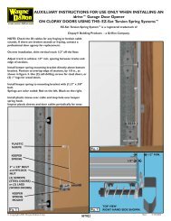
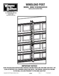
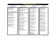
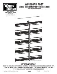
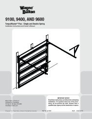
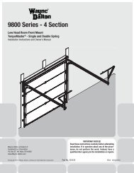
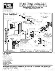
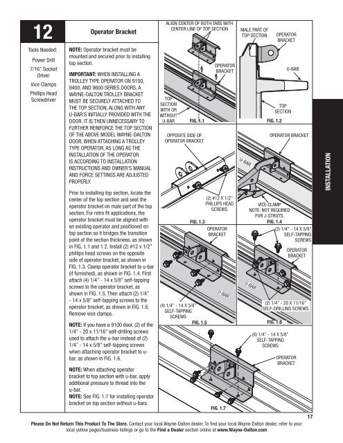
12Tools Needed:Power Drill7/16” SocketDriverVice ClampsPhillips HeadScrewdriverOperator BracketNOTE: Operator bracket must bemounted and secured prior to installingtop section.IMPORTANT: When installing atrolley type operator on <strong>9100</strong>,<strong>9400</strong>, and <strong>9600</strong> Series doors, a<strong>Wayne</strong>-<strong>Dalton</strong> trolley bracketmust be securely attached tothe top section, along with anyu-bar’s initially provided with thedoor. It is then unnecessary tofurther reinforce the top sectionof the above model <strong>Wayne</strong>-<strong>Dalton</strong>door, when attaching a trolleytype operator, as long as theinstallation of the operatoris according to Installationinstructions and owner’s manualand force settings are adjustedproperly.Prior to installing top section, locate thecenter of the top section and seat theoperator bracket on male part of the topsection. For retro fit applications, theoperator bracket must be aligned withan existing operator and positioned ontop section so it bridges the transitionpoint of the section thickness, as shownin FIG. 1.1 and 1.2. Install (2) #12 x 1/2”phillips head screws on the oppositeside of operator bracket, as shown inFIG. 1.3. Clamp operator bracket to u-bar(if furnished), as shown in FIG. 1.4. Firstattach (4) 1/4” - 14 x 5/8” self-tappingscrews to the operator bracket, asshown in FIG. 1.5. Then attach (2) 1/4”- 14 x 5/8” self-tapping screws to theoperator bracket, as shown in FIG. 1.6.Remove vice clamps.NOTE: If you have a <strong>9100</strong> door, (2) of the1/4” - 20 x 11/16” self-drilling screwsused to attach the u-bar instead of (2)1/4” - 14 x 5/8” self-tapping screwswhen attaching operator bracket to u-bar, as shown in FIG. 1.6.NOTE: When attaching operatorbracket to top section with u-bar, applyadditional pressure to thread into theu-bar.NOTE: See FIG. 1.7 for installing operatorbracket on top section without u-bars.Align center of both tabs withcenter line of top sectionTopsectionWith orwithoutU-barFIG. 1.1Opposite side ofOperator bracketFIG. 1.3(4) 1/4” - 14 x 5/8”self-tappingscrewsFIG. 1.5OperatorBracket(2) #12 x 1/2”Phillips headscrewsOperatorbracketMale part oftop sectionOperatorBracketTopsectionFIG. 1.2Please Do Not Return This Product To The Store. Contact your local <strong>Wayne</strong>-<strong>Dalton</strong> dealer. To find your local <strong>Wayne</strong>-<strong>Dalton</strong> dealer, refer to yourlocal yellow pages/business listings or go to the Find a Dealer section online at www.<strong>Wayne</strong>-<strong>Dalton</strong>.comU-barFIG. 1.7U-barU-barOperator BracketVice clampNOTE: not requiredfor j-struts.FIG. 1.4(2) 1/4” - 14 x 5/8”self-tappingscrewsU-bar(2) 1/4” - 20 x 11/16”self-DRILLING screwsFIG. 1.6(6) 1/4” - 14 x 5/8”Self-tappingscrewsOperatorbracketOperatorbracket17INSTALLATION