TorqueMaster SD Spring - 9100 9400 9600 - Wayne Dalton
TorqueMaster SD Spring - 9100 9400 9600 - Wayne Dalton
TorqueMaster SD Spring - 9100 9400 9600 - Wayne Dalton

Create successful ePaper yourself
Turn your PDF publications into a flip-book with our unique Google optimized e-Paper software.
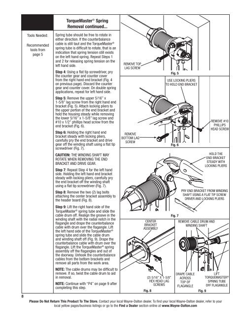
<strong>TorqueMaster</strong> ® <strong>Spring</strong>Removal continued...8Tools Needed:Recommendedtools frompage 5<strong>Spring</strong> tube should be free to rotate ineither direction. If the counterbalancecable is still taut and the <strong>TorqueMaster</strong> ®spring tube is difficult to rotate, that is anindication that spring tension still existson the left hand spring. Repeat Steps 1and 2 for releasing spring tension on theleft hand side.Step 4: Using a flat tip screwdriver, prythe counter gear and counter coverfrom the right hand end bracket (Fig. 4on previous page). Discard the countergear and counter cover. On double springapplications, repeat for left hand side.Step 5: Remove the upper 5/16” x1-5/8” lag screw from the right hand endbracket (Fig. 5). Attach locking pliers tothe upper portion of the end bracket andhold the housing steady while removingthe lower 5/16” x 1-5/8” lag screw and#10 x 1/2” phillips head screw from theend bracket (Fig. 6).Step 6: Holding the right hand endbracket steady with locking pliers,carefully pry the end bracket and drivegear off the winding shaft using a flat tipscrewdriver (Fig. 7).CAUTION: THE WINDING SHAFT MAYROTATE WHEN REMOVING THE ENDBRACKET AND DRIVE GEAR.Step 7: Repeat Step 4 for the left handside. Holding the left hand end bracketsteady with locking pliers, carefully prythe end bracket off the winding shaftusing a flat tip screwdriver (Fig. 7).Step 8: Remove the two (2) lag boltsattaching the center bracket assembly tothe header board (Fig. 8).Step 9: Lift the right hand side of the<strong>TorqueMaster</strong> ® spring tube and slide thecable drum off. Realign the groove in thewinding shaft with the radial notch in theflagangle and drape the counterbalancecable with drum over the flagangle. Liftthe left hand side of the <strong>TorqueMaster</strong> ®spring tube and slide the cable drumand winding shaft off (Fig. 9). Drape thecounterbalance cable with drum over theflagangle. Lift the <strong>TorqueMaster</strong> ® springassembly off the flagangles and out ofthe doorway. Unhook the counterbalancecables from the bottom brackets andremove all parts from the work area.NOTE: The cable drums may be difficult toremove. If so, twist the cable drum to aidin removal.NOTE: Continue with “P4” on page 9 aftercompleting this step.remove toplag screwremovebottom lagscrewCENTERBRACKETASSEMBLY(2) 5/16” x 1-5/8”hex head lagscrewsPlease Do Not Return This Product To The Store. Contact your local <strong>Wayne</strong>-<strong>Dalton</strong> dealer. To find your local <strong>Wayne</strong>-<strong>Dalton</strong> dealer, refer to yourlocal yellow pages/business listings or go to the Find a Dealer section online at www.<strong>Wayne</strong>-<strong>Dalton</strong>.comFig. 8Fig. 5use locking pliersto hold end bracketFig. 6Fig. 7remove cable drum andwinding shaftremove #10phillipshead screwhold theend bracketsteady withlocking plierspry end bracket from windingshaft using a flat tip screwdriver and locking pliersdrape cableacrosstop offlaganglelift<strong>TorqueMaster</strong> ®<strong>Spring</strong> Tubeoff flagangleFig. 9