TorqueMaster Plus Standard Lift - Wayne Dalton
TorqueMaster Plus Standard Lift - Wayne Dalton
TorqueMaster Plus Standard Lift - Wayne Dalton
- No tags were found...

You also want an ePaper? Increase the reach of your titles
YUMPU automatically turns print PDFs into web optimized ePapers that Google loves.
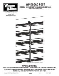
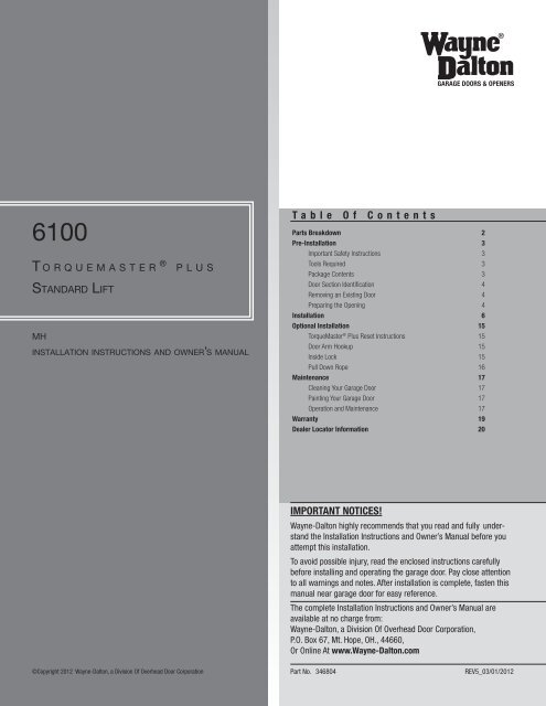
GARAGE DOORS & OPENERS6100T o r q u e m a s t e r ® p l u s<strong>Standard</strong> <strong>Lift</strong>MHinstallation instructions and owner’s manualT a b l e O f C o n t e n t sParts Breakdown 2Pre-Installation 3Important Safety Instructions 3Tools Required 3Package Contents 3Door Section Identification 4Removing an Existing Door 4Preparing the Opening 4Installation 6Optional Installation 15<strong>TorqueMaster</strong> ® <strong>Plus</strong> Reset Instructions 15Door Arm Hookup 15Inside Lock 15Pull Down Rope 16Maintenance 17Cleaning Your Garage Door 17Painting Your Garage Door 17Operation and Maintenance 17Warranty 19Dealer Locator Information 20IMPORTANT NOTICES!<strong>Wayne</strong>-<strong>Dalton</strong> highly recommends that you read and fully understandthe Installation Instructions and Owner’s Manual before youattempt this installation.To avoid possible injury, read the enclosed instructions carefullybefore installing and operating the garage door. Pay close attentionto all warnings and notes. After installation is complete, fasten thismanual near garage door for easy reference.The complete Installation Instructions and Owner’s Manual areavailable at no charge from:<strong>Wayne</strong>-<strong>Dalton</strong>, a Division Of Overhead Door Corporation,P.O. Box 67, Mt. Hope, OH., 44660,Or Online At www.<strong>Wayne</strong>-<strong>Dalton</strong>.com©Copyright 2012 <strong>Wayne</strong>-<strong>Dalton</strong>, a Division Of Overhead Door CorporationPart No.346804 REV5_03/01/2012
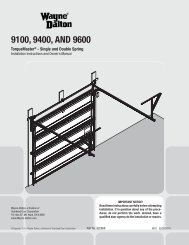
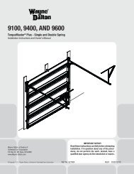
Parts BreakdownNOTE: The illustrations shown on this page are generalrepresentations of the door parts. Each specific doormodels may have unique variations.J9.J6.A2.A1.J4.J1.C1.I2.K2.J2.F2.G2.H3.J8.F3.F1.G1.H2.J5.E1.J7.J3.F2.C1.F3.F1.E2.B2.B1.H1.Top of verticaltrack3rd holesetTop of verticaltrackFullyAdjustableFeatureA1. A2.B2.B1.D2.D4.C2.D3.K1.E3.E4.I1.I4.2ndhole setB2. (QuickInstallFeature)Tophole3rdhole set2ndhole setI3.D1.C1.1st holesetMiddleholeBottomhole1sthole setLower holeof hole/slot patternA. Flag Angles (As Required):A1. Fully Adjustable (F.A.) Flag AnglesA2. Quick Install (Q.I.) Flag AnglesB. Jamb Brackets (As Required):B1. Fully Adjustable (F.A.) Jamb BracketsB2. Quick Install (Q.I.) Jamb BracketsC. Track Rollers:C1. Short Stem Track RollersC2. Long Stem Track RollersD. Graduated End Hinges:D1. Single Graduated End Hinges (S.E.H.), Anti-PinchD2. Single Graduated End Hinges (S.E.H.), Industry <strong>Standard</strong>D3. Double Graduated End Hinges (D.E.H.), Anti-PinchD4. Double Graduated End Hinges (D.E.H.), Industry <strong>Standard</strong>E. Stacked Sections:E1. Top SectionE2. Intermediate(s) SectionE3. Lock SectionE4. Bottom SectionF. Top Fixtures (As Required):F1. Top Fixture Bases - (L-Shaped)F2. Top Fixture Slides - (L-Shaped)F3. Top Fixture Assemblies – (A-Shaped)G. Strut(s) (As Required):G1. Strut (U-shaped)G2. Strut (A-symmetrical)H. Drawbar Operator Bracket (For Trolley Operated Doors):H1. Top Half Drawbar Operator BracketH2. Bottom Half Drawbar Operator BracketH3. Drawbar Operator Bracket ArmI. Tracks:I1. Left Hand Horizontal Track AssemblyI2. Right Hand Horizontal Track AssemblyI3. Left Hand Vertical TrackI4. Right Hand Vertical TrackJ. <strong>TorqueMaster</strong> <strong>Plus</strong> ® Spring Assembly:J1. Center Bracket Bushing AssemblyJ2. <strong>TorqueMaster</strong> ® Spring Tube (Single Or Double Springs)J3. Left Hand End BracketJ4. Right Hand End Bracket (Disconnect Cable Guide)J5. Left Hand Cable Drum AssemblyJ6. Right Hand Cable Drum AssemblyJ7. Loose Winding Shaft (Single Spring Only)J8. Left Hand Drum Wrap (As Required)J9. Right Hand Drum Wrap (As Required)K. Rear Back Hangs:K1. Left Hand Rear Back Hang AssembliesK2. Right Hand Rear Back Hang Assemblies2Please Do Not Return This Product To The Store. Contact your local <strong>Wayne</strong>-<strong>Dalton</strong> dealer. To find your local <strong>Wayne</strong>-<strong>Dalton</strong> dealer,refer to your local yellow pages business listings or go to the Find a Dealer section online at www.<strong>Wayne</strong>-<strong>Dalton</strong>.com
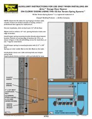
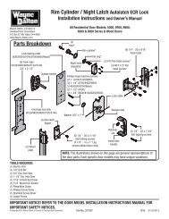
1-9/16”5/16” x 1 5/8” Hex head lag screws(as required)1/4”-20 x 11/16” Selfdrilling screws (as required)#3Warning labelTop sectionWarning label1-3/8”#3 Graduatedend hinge#4Graduatedend hinge1/4”-20 x 9/16”Track bolts (as required)(2) 5/16”-18 x 3/4”Carriage bolts#2Intermediate section1-1/8”#2 Graduatedend hingeDrawbar operatorbracket arm(2) 3/8”-16 x 3/4”Truss head bolts1/4”-14 x 5/8” Self tappingscrews (as required)#1Lock sectionBottom corner bracket warning labels7/8”#1 Graduatedend hingePull handles (as required)5/16” x 1-1/4” Clevis pin<strong>Lift</strong> handles (as required)Cotter pin#10 x 5/8”Phillips pan head screws(black painted heads)AstragalTypical graduated endhinge stampinglocationBottom sectionBottom cornerbracketAstragalSection side view illustration#8 x 1-21/32” Quadrex pan head screws#8 x 1-13/32” Quadrex pan head screwsDoor Section IdentificationGraduated end and center hinges are always pre-attached at the top of each section (excepttop section) and the graduated end hinges are stamped for identification, #1, #2, #3, and #4(#4 only on five section doors). The stamp identifies the stacking sequence of the section. Thesequence is always determined by #1 being the bottom section to #3 or #4 being the highestintermediate section. If the stamp on the graduated end hinge is illegible, refer to the sectionside view illustration. The section side view illustration shows the graduated end hinge profile ofall sections, and can also be used to identify each section.The BOTTOM SECTION can be identified by #1 graduated end hinges, the factory attachedbottom astragal, the factory attached bottom corner brackets, and by the bottom corner bracketwarning labels on each end stile.The LOCK SECTION can be identified by #2 graduated end hinges.The INTERMEDIATE SECTION can be identified by #3 graduated end hinges. The section willhave a warning label attached to either the right or left hand end stile.Note: #4 graduated end hinges are used on the fourth section of five section doors.The TOP SECTION can be identified with no pre-installed graduated end or center hinges.Removing an Existing DoorImportant: Counterbalance spring tension must always be released before anyattempt is made to start removing an existing door.WARNINGA powerful spring releasing its energy suddenly can cause severeor fatal injury. To avoid injury, have a trained door systems technician,using proper tools and instructions, release the springtension.For detailed information see supplemental instructions “Removing an Existing Door/ Preparingthe Opening”. These instructions are not supplied with the door, but are available at no chargefrom <strong>Wayne</strong>-<strong>Dalton</strong>, A Division Of Overhead Door Corporation, P.O. Box 67, Mt. Hope, OH.,44660, or at www.<strong>Wayne</strong>-<strong>Dalton</strong>.com.Preparing the OpeningIMPORTANT: If you just removed your existing door or you are installing a newdoor, complete all steps in preparing the opening.To ensure secure mounting of track brackets, side and center brackets, or steel angles to new orretro-fit construction, it is recommended to follow the procedures outlined in DASMA technicaldata sheets #156, #161 and #164 at www.dasma.com.The inside perimeter of your garage door opening should be framed with wood jamb and headermaterial. The jambs and header must be securely fastened to sound framing members. It isrecommended that 2” x 6” lumber be used. The jambs must be plumb and the header level. Thejambs should extend a minimum of 12” (305 mm) above the top of the opening for <strong>TorqueMaster</strong>® counterbalance systems. For low headroom applications, the jambs should extend to theceiling height. Minimum side clearance required, from the opening to the wall, is 3-1/2” (89mm).Important: Closely inspect jambs, header and mounting surface. Any woodfound not to be sound, must be replaced.For <strong>TorqueMaster</strong> ® counterbalance systems, a suitable mounting surface (2” x 6”) must be firmlyattached to the wall, above the header at the center of the opening.Note: Drill a 3/16” pilot hole in the mounting surface to avoid splitting the lumber. Do not attachthe mounting surface with nails.Weatherstrips (may not be included):Depending on the size of your door, you may have to cut or trim the weatherstrips (if necessary)to properly fit into the header and jambs.Note: If nailing product at 40°F or below, pre-drilling is required.Note: Do not permanently attach weatherstrips to the header and jambs at this time.For Quick Install track: For the header, align the weatherstrip with the inside edge of the headerand temporarily secure it to the header with equally spaced nails. Starting at either side of the4Please Do Not Return This Product To The Store. Contact your local <strong>Wayne</strong>-<strong>Dalton</strong> dealer. To find your local <strong>Wayne</strong>-<strong>Dalton</strong> dealer,refer to your local yellow pages business listings or go to the Find a Dealer section online at www.<strong>Wayne</strong>-<strong>Dalton</strong>.com
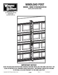
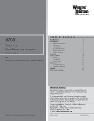
jamb, fit the weatherstrip up tight against the temporarily attached weatherstrip in the headerand flush with the inside edge of the jamb. Temporarily secure the weatherstrip with equallyspaced nails. Repeat for other side. This will keep the bottom section from falling out of theopening during installation. Equally space nails approximately 12” to 18” apart.For Fully Adjustable track: For the header, align the weatherstrip 1/8” to 1/4” inside the headeredge, and temporarily secure it to the header with equally spaced nails. Starting at either sideof the jamb, fit the weatherstrip up tight against the temporarily attached weatherstrip in theheader and 1/8” to 1/4” inside the jamb edge. Temporarily secure the weatherstrip with equallyspaced nails. Repeat for other side. This will keep the bottom section from falling out of theopening during installation. Equally space nails approximately 12” to 18” apart.Headroom requirement: Headroom is defined as the space needed above the top of the doorfor tracks, springs, etc. to allow the door to open properly. If the door is to be motor operated,2-1/2” (64 mm) of additional headroom is required.Note: 6” low headroom conversion kit is available for 12” radius only. Contact your local<strong>Wayne</strong>-<strong>Dalton</strong> dealer.Backroom requirement: Backroom is defined as the distance needed from the opening backinto the garage to allow the door to open fully.Backroom RequirementsDOOR HEIGHT TRACK MANUAL LIFT MOTOR OPERATED6’5” to 7’0” 12”,15” Radius 98” (2489 mm) 125” (3175 mm)7’1” to 8’0” 12”,15” Radius 110” (2794 mm) 137” (3480 mm)Headroom RequirementsTRACK TYPESPACE NEEDED15” Radius track 13-1/2” (343 mm)12” Radius track 11” (279 mm)6” LHR Kit 6” (152 mm)Suitable mounting surface2”x 6” lumber minimumHeader board 2”x 6”lumber preferredHeadroomMin. SideroomClearanceis 3 1/2”Min. SideroomClearanceis 3 1/2”FinishedDoorHeightLevel headerWeatherstripsNailBackroomPlumbjambsJambsFinishedDoor widthJambQuick Install trackJambFully Adjustable track1/8” to 1/4”WeatherstripsWeatherstrips5Please Do Not Return This Product To The Store. Contact your local <strong>Wayne</strong>-<strong>Dalton</strong> dealer. To find your local <strong>Wayne</strong>-<strong>Dalton</strong> dealer,refer to your local yellow pages business listings or go to the Find a Dealer section online at www.<strong>Wayne</strong>-<strong>Dalton</strong>.com
InstallationQuickInstalltabsHorizontal trackangleBefore installing your door, be certain that you have read and followed all of the instructionscovered in the pre-installation section of this manual. Failure to do so may result in animproperly installed door.NOTE: Reference TDS 160 for general garage door terminology at www.dasma.com.1Quick Install Flag AnglesTools: NoneNote: If you have Fully Adjustable flag angles, skip this step.NOTE: If you have riveted track, skip this step.Note: Flag angles are right and left handed.Place the lower Quick Install tab of the left hand flag angle in the Quick Install feature of theleft hand vertical track. Give the flag angle 1/4 turn to lock in place. Repeat for other side.Flag angle1/4 Turn4AlignmentholeKey slotsHorizontaltrackQuick Install Jamb BracketsTools: NoneQuick Install tabsin placeNote: If you have Fully Adjustable jamb brackets, skip this step.NOTE: If you have riveted track, skip this step.Measure the length of the vertical tracks. Using the jamb bracket schedule, determine theplacement of the jamb brackets for your door height and track length. To install the jambbrackets, align the Quick Install tab on the Quick Install jamb bracket with the Quick Installfeature in the vertical track and turn the bracket perpendicular to the track so the mountingflange is toward the back (flat) leg of the track. Repeat for other side.1st hole set2nd hole setVertical track3rd hole setTop of track2VerticaltrackLowerQuickInstall tabQuickInstallfeatureFully Adjustable Flag AnglesTools: NoneNote: If you have Quick Install flag angles, skip this step.NOTE: If you have riveted track, skip this step.Note: Flag angles are right and left handed.If you have Quick Install vertical tracks, hand tighten the left hand flag angle to the left handvertical track using (1) stud plate and (2) 1/4” – 20 flange hex nuts. Repeat for the other side.If you have Fully Adjustable vertical tracks, hand tighten the left hand flag angle to the lefthand vertical track using (2) 1/4”-20 x 9/16” track bolts and (2) 1/4”-20 flange hex nuts.Repeat for other side. Flange nuts will be secured after flag angle spacing is completed instep, Top Section.Flag angle1/4”-20Flange hex nutsQuick Installverticaltrack3StudplateFlag angle1/4”-20Flange hex nutsFully AdjustableverticaltrackHorizontal Track AnglesTools: Hammer1/4”- 20 x 9/16”Track boltsNOTE: For larger doors, a full length horizontal track angle may not already be spot welded tothe horizontal track. If the horizontal track angle is not welded, the horizontal track angle willbe installed, as shown.Position the left hand horizontal track angle, as shown. Place the Quick Install tabs of thehorizontal track angle in the key slot of the left hand horizontal track. Using a hammer, tapthe horizontal track angle towards the curved end of the track until the alignment hole in thetrack and angle are aligned. Repeat for other side. Set tracks aside.Bottom holeMiddle holeTop holeDOOR HEIGHT7’0”8’0” 4-SEC5Q.I. tabQ.I. jambbracketTRACKLENGTH76” (1930mm)88”(2235mm)JAMB BRACKET SCHEDULEJamb bracketin placeMounting flange1ST SET 2ND SET 3RD SET6 B 8 B NA7 M 8 B 10 TB= BOTTOM HOLE, M= MIDDLE HOLE, T= TOP HOLEFully Adjustable Jamb BracketsTools: NoneNote: If you have Quick Install jamb brackets, skip this step.NOTE: If you have riveted track, skip this step.Note: The bottom jamb bracket is always the shortest bracket, while the center jambbracket is the next tallest. If three jamb brackets per side are included with your door, you willhave received a top jamb bracket, which is the tallest.To attach the bottom jamb bracket, locate lower hole of the hole/ slot pattern of the 1st holeset on the vertical track. Align the slot in the jamb bracket with the lower hole of the hole/ slotpattern. Secure jamb bracket using (1) 1/4”-20 x 9/16” track bolt and (1) 1/4”-20 flange hexnut. Repeat for other side.Place the center jamb bracket over the lower hole of the hole/ slot pattern that is centeredbetween the bottom jamb bracket and flag angle of the 2nd hole set. Secure jamb bracketusing (1) 1/4”-20 x 9/16” track bolt and (1) 1/4”-20 flange hex nut. Repeat for other side.If a top jamb bracket was included, secure it to vertical track using the lower hole of the hole/slot pattern in the 3rd hole set and (1) 1/4”-20 x 9/16” track bolt and (1) 1/4”-20 flange hexnut. Repeat for other side.6Please Do Not Return This Product To The Store. Contact your local <strong>Wayne</strong>-<strong>Dalton</strong> dealer. To find your local <strong>Wayne</strong>-<strong>Dalton</strong> dealer,refer to your local yellow pages business listings or go to the Find a Dealer section online at www.<strong>Wayne</strong>-<strong>Dalton</strong>.com
(2) 1/4”-20 x 11/16”Self drilling screws(2) 1/4”-14 x 5/8”Self tapping screws(2) 1/4”-14 x 5/8”Self tapping screws(2) 1/4”-20 x 11/16”Self drilling screwsStrut (A-symmetrical) End cap(attached to top rib)Lock section30” To 36”Left double graduatedend hinge with longstem track rollerRight double graduatedend hinge with longstem track roller12Verticaltracks1/4”-14 x 5/8” Self tapping screw locationsLeft graduated end hingewith short stem track rollerCenterhinge(s)Secure topmiddlehole firstRight graduated end hingewith short stem track rollerTop FixturesTools: Power drill, 7/16” Socket driver, Phillips screwdriverTo install the top fixtures, align the top holes in the top fixture base with the second set ofholes in the end cap of the top section. Fasten to section using (4) 1/4”-14 x 5/8” self tappingscrews. Secure the top fixture slide to the fixture base loosely using (2) 1/4”-20 x 5/8”carriage bolts and (2) 1/4”-20 flange hex nuts.Fasten (2) Quadrex Pan Head screws, one in the middle hole of the top fixture base and theother in the corresponding hole below the top fixture base.NOTE: If you have 7’0” door height, use (2) #8 x 1-13/32” quadrex pan head screws.NOTE: If you have 8’0” door height, use (2) #8 x 1-21/32” quadrex pan head screws.The top fixture slide will be tightened and adjusted later, in step, Adjusting Top Fixture. Insertshort stem track roller into top fixture slide. Repeat same process for other side.Top fixture slideShort stem track roller(4) 1/4”- 14 x 5/8”Self-tapping screws(2) Quadrex panhead screws13(2) 1/4”- 20 x 5/8”Carriage boltsTop sectionEnd cap2nd SetTop fixturebase(2) 1/4”- 20Flange hex nutsStrut (A-symmetrical)Tools: Power drill, 7/16” Socket driver, Tape measureEndcap hole pattern2nd SetNOTE: If an a-symmetrical strut is supplied, complete this step.Place the a-symmetrical strut over the top rib of the top door section. Fasten each end ofthe a-symmetrical strut to the end cap with (2) 1/4”-20 x 11/16” self drilling screws. Fastenboth wall and the long leg of the a-symmetrical strut, as shown using (2) 1/4”-14 x 5/8”self tapping screws every 30-36 inches. (Approximately 18 self tapping screws per 18’a-symmetrical strut)IMPORTANT: When securing the a-symmetrical strut to the top section, itis recommended not to install any fasteners into the short leg of the a-symmetrical strut.14Strut (A-symmetrical) side viewLong legShort legDrawbar Operator BracketTools: Power drill, 7/16” Socket driver, Flat head screwdriver, 7/16”Wrench, Tape measure, PencilImportant: when connecting a drawbar operator type garage door openerto this door, a <strong>Wayne</strong>-<strong>Dalton</strong> operator/ drawbar operator bracket mustbe securely attached to the top section of the door, along with any strutprovided with the door. The installation of the drawbar operator must be accordingto manufacturer’s instructions and force settings must be adjustedproperly.Position the drawbar operator bracket arm inside the top portion of the top half of drawbaroperator bracket and flush against the back of the top half of drawbar operator bracket.Adjust the top holes in the drawbar operator bracket arm with the two upper holes in the tophalf of drawbar operator bracket.Fasten both the drawbar operator bracket arm and the top half of drawbar operator brackettogether using (2) 1/4”-20 x 9/16” track bolts and (2) 1/4”-20 flange hex nuts.Slide the bottom half of drawbar operator bracket inside the top half of drawbar operatorbracket. Adjust the both the top and bottom halves of drawbar operator brackets out againstthe top and bottom rib of the top section. Loosely fasten both the top and bottom halves ofdrawbar operator brackets together using (4) 1/4”-20 x 9/16” track bolts and (4) 1/4”-20flange hex nuts.NOTE: Install the 1/4”-20 x 9/16” track bolts and the 1/4”-20 flange hex nuts as far apartas possible, when positioning both the top and bottom halves of drawbar operator bracketstogether.NOTE: For retro fit applications, the drawbar operator bracket assembly must be aligned withan existing drawbar operator.Now, locate the center of the top section and align the center of the holes in the drawbar operatorbracket assembly with the top section center line. Align the drawbar operator bracketassembly vertically.First, secure the back of the drawbar operator bracket assembly to the top section insidesurface using (2) 1/4”-20 x 11/16” self drilling screws. Next, secure the drawbar operatorbracket assembly to the top and bottom ribs of the top section using (8) 1/4”-20 x 11/16”self drilling screws. Now, tighten all previously installed 1/4”-20 x 9/16” track bolts and1/4”-20 flange hex nuts.Secure the drawbar operator bracket assembly to the top section using (1) quadrex pan headscrew.NOTE: If you have 7’0” door height and your door width is less than or equal to 16’0”, use (1)#8 x 1 21/32” quadrex pan head screw.NOTE: If you have 7’0” door height and your door width is greater than 16’0”, use (1) #8 x 113/32” quadrex pan head screw.NOTE: For door heights greater than 7’0”, use (1) #8 x 1 13/32” quadrex pan head screw.(2) 1/4”-20 x9/16” Track bolts Top riband (2) 1/4”–20 Flange hex nutsDrawbar operatorbracket armTop half of drawbaroperator bracketTop half of drawbaroperator bracket(4) 1/4”-20 x9/16” Track boltsand (4) 1/4”–20 Flange hex nutsBottom half of drawbaroperator bracketBottom ribTopsectioninsidesurface9Please Do Not Return This Product To The Store. Contact your local <strong>Wayne</strong>-<strong>Dalton</strong> dealer. To find your local <strong>Wayne</strong>-<strong>Dalton</strong> dealer,refer to your local yellow pages business listings or go to the Find a Dealer section online at www.<strong>Wayne</strong>-<strong>Dalton</strong>.com
Drawbar operatorbracket armTop half ofdrawbaroperatorbracketTop ribBottom half of drawbaroperator bracket15BottomribTop sectionsurfaceTop SectionTools: Hammer, Step ladder, Tape measure1/4” -20 X 11/16”Self drilling screwsQuadrex panhead screwPlace the top section in the opening. Temporarily secure the top section by driving a nail intothe header near the center of the door and bending it over the top section. Now, flip up thegraduated end and center hinge leaves, hold tight against section, and fasten center hingesfirst and end hinges last (refer to step, Stacking Sections). Vertical track alignment is critical.Position flag angle between 1-11/16” (43 mm) to 1-3/4” (44 mm) from the edge of the door;tighten the bottom lag screw. Flag angles must be parallel to the door sections. Repeat sameprocess for other side.Important: the dimension between the flag angles must be door width plus3-3/8” (86mm) to 3-1/2” (89 mm) for smooth, safe door operation.For Quick Install Track:Complete the vertical track installation by securing the jamb bracket(s) and tightening theother lag screws. Repeat for other side.For Fully Adjustable track:Complete the vertical track installation by securing the jamb bracket(s) and tightening theother lag screws. Push the vertical track against the track rollers so that the track rollers aretouching the deepest part of the curved side of the track; tighten all the track bolts and nuts.Repeat for other side.Flagangle16Flag angle1-11/16”to 1-3/4”TopsectionDoor width+ 3-3/8” to 3-1/2”NailTop sectionVertical trackagainst track rollersHorizontal Tracks/Q.I. Flag AnglesTools: Ratchet wrench, 9/16” Socket, 9/16” Wrench, level, Step ladderNote: If you have Quick Install flag angles, complete this step.To install horizontal track, place the curved end over the top track roller of the top section.Align key slot of the horizontal track with the Quick Install tab of the flag angle. Push curvedportion of horizontal track down to lock in place.WARNINGDo not raise door until horizontal tracks are secured at rear,as outlined in Step, Rear Back Hangs, or door could fall fromoverhead position causing severe or fatal injury.Level the horizontal track assembly and bolt the horizontal track angle to the first encounteredslot in the flag angle using (1) 3/8”-16 x 3/4” truss head bolt and (1) 3/8”-16 hex nut.Repeat for other side.Remove the nail that was temporarily holding the top section in place, installed in step, TopSection.Important: Failure to remove nail before attempting to raise door couldcause permanent damage to top section.Note: If an idrive ® opener will be installed, position horizontal tracks slightly above level.Flag angleHorizontaltrackQuickInstall tab17QuickInstall tabin placeTracks flushKey slot3/8”-16Hex nutFlag angleHorizontal trackangle3/8”-16 x 3/4”Truss head boltHorizontal Tracks/F.A. Flag AnglesTools: Ratchet wrench, 7/16” Socket, 9/16” Socket, 9/16” Wrench,level, Step ladderNote: If you have Fully Adjustable flag angles, complete this step.To install horizontal track, place the curved end over the top track roller of the top section.Align the bottom of the horizontal track with the top of the vertical track. If you have QuickInstall horizontal track, tighten the horizontal track to the flag angle with a stud plate and (2)1/4”-20 flange hex nuts. If you have Universal horizontal track, tighten the horizontal track tothe flag angle with (2) 1/4”-20 x 9/16” track bolts and (2) 1/4”-20 flange hex nuts.WARNINGDo not raise door until horizontal tracks are secured at rear,as outlined in step, Rear Back Hangs, or door could fall fromoverhead position causing severe or fatal injury.Level the horizontal track assembly and bolt the horizontal track angle to the first encounteredslot in the flag angle using (1) 3/8”-16 x 3/4” truss head bolt and (1) 3/8”-16 hex nut.Repeat for other side.Remove the nail that was temporarily holding the top section in place, installed in step, TopSection.Important: Failure to remove nail before attempting to raise door couldcause permanent damage to top section.Note: If an idrive ® opener will be installed, position horizontal tracks slightly above level.Quick Installhorizontaltrack1/4”-20Flange hex nutsFlag angleupper slot18Fully Adjustablehorizontal trackStudplate1/4”-20Flange hex nutsFlag angleupper slotAdjusting Top FixturesTools: 7/16” Wrench, Step ladderHorizontaltrack angle1/4”-20 x 9/16”Track bolts3/8”-16Hex nut3/8”-16 x 3/4”Truss head boltWith horizontal tracks installed, you can now adjust the top fixtures. Vertically align the topsection of the door with the lower sections. Once aligned, position the top fixture slide, outagainst the horizontal track. Maintaining the slide’s position, tighten the (2) 1/4”-20 flangehex nuts to secure the top fixture slide to the top fixture base. Repeat for other side.19Horizontal track(2) 1/4”- 20Flange hex nutsTop sectionTop fixture slideTop fixture base<strong>TorqueMaster</strong> ® Spring TubeTools: None<strong>TorqueMaster</strong> ® springs come lubricated and pre-assembled inside the <strong>TorqueMaster</strong> ® springtube. To prepare for install, lay the spring tube assembly on the floor, inside garage, in front ofthe door, and with the labeled end to the left.10Please Do Not Return This Product To The Store. Contact your local <strong>Wayne</strong>-<strong>Dalton</strong> dealer. To find your local <strong>Wayne</strong>-<strong>Dalton</strong> dealer,refer to your local yellow pages business listings or go to the Find a Dealer section online at www.<strong>Wayne</strong>-<strong>Dalton</strong>.com
20Label<strong>TorqueMaster</strong> ® spring tubeCenter Bracket Bushing AssemblyTools: NoneNote: If you are installing the idrive ® opener with your garage door, skip this step and goto your idrive ® Installation Instructions and Owner’s Manual. After completing the steps upto and including, Drum Wrap Installation of your idrive ® Installation Instructions and Owner’sManual continue with Step, Rear Back Hangs, of this door Installation Instructions andOwner’s Manual.Note: If you are not installing the idrive ® opener on your garage door, you must install thecenter bracket bushing assembly. Follow these instructions for non-idrive ® operated garagedoors.Being cam shaped, the center bushing only fits one way. Slide the center bracket bushing assemblytowards the center of the <strong>TorqueMaster</strong> ® spring tube, from the right side, as shown.<strong>TorqueMaster</strong> ®spring tube21Center bracket bushing assemblyDrum WrapsTools: NoneCenter bracketCenter bushingCam peakon top of the flag angles.NOTE: Cable drum assemblies are marked right and left hand. Cable drums and <strong>TorqueMaster</strong>® spring tube assembly is cam shaped to fit together only one way.Starting on the right hand side, pre-wrap the cable drum with the counterbalance lift cable1-1/2 wraps, as shown.Position the <strong>TorqueMaster</strong> ® spring tube assembly so the cam peak is pointing straight up.Slide the cable drum over the winding shaft until the cable drum seats against the Torque-Master ® spring tube assembly.The winding shaft must extend past the cable drum far enough to expose the splines and thegrooves. Align the winding shaft grooves with the round notch in the flag angle.For double spring applications: Repeat for left hand side.For single spring applications: Pre-wrap the left hand cable drum with the counterbalancelift cable 1-1/2 wraps and insert the loose winding shaft into the cable drum, prior tosliding the cable drum over the <strong>TorqueMaster</strong> ® spring tube assembly.NOTE: On single spring applications, take care in handling the loose winding shaft (left handside), so that it does not slide back into the <strong>TorqueMaster</strong> ® spring tube assembly.Winding shaftCam peakstraight<strong>TorqueMaster</strong> ® springtube assembly235”Counterbalance lift cable1-1/2 wrapsRight cabledrumRound notchSplinesGroovesCable drumLoose winding shaftEnd BracketsTools: Power drill, 7/16” Socket driver, 1/2” Wrench, Step ladderWindingshaftFlagangleIMPORTANT: Warning tags must be securely attached to both end brackets.End brackets are right and left hand. You can identify the right hand end bracket by thedisconnect cable guide hole, located at the top of the end bracket.Beginning with the right hand side, slide the end bracket onto the winding shaft so that thesplines in the ratchet wheel fit onto the winding shaft grooves.Attach the end bracket to the flag angle using (1) 5/16”-18 x 3/4” carriage bolt, (1) 5/16”washer and (1) 5/16”-18 hex nut. Then secure the end bracket to the jamb using (1) 5/16” x1-5/8” lag screw.Repeat same process for left hand end bracket.NOTE: If ratchet wheel falls out of end bracket, refer to illustration for proper insertionorientation.NOTE: On single spring applications, no ratchet wheel is required on the left hand side.NOTE: If you don’t have drum wraps, then skip this step. Refer to Package Contents / PartsBreakdown, to determine if you have drum wraps.Drum wraps are marked right and left hand. Beginning with the left hand side, slide the lefthand drum wrap onto the <strong>TorqueMaster</strong> ® spring tube. Repeat for the right hand side. Thedrum wrap will be secured later, in Step, Securing Drum Wraps.Left handdrum wrapRight handdrum wrapFlag angleGroovesWindingshaftSplinesDisconnect cableguide holeWarning tagRight hand end bracket<strong>TorqueMaster</strong> ® spring tube22LabelCable Drum AssembliesTools: Tape measure, Step ladderShake the <strong>TorqueMaster</strong> ® spring tube assembly gently to extend the winding shafts outabout 5” on each side. For single spring applications, there will be no left hand spring in the<strong>TorqueMaster</strong> ® spring tube assembly. <strong>Lift</strong> the <strong>TorqueMaster</strong> ® spring tube assembly and rest it11Please Do Not Return This Product To The Store. Contact your local <strong>Wayne</strong>-<strong>Dalton</strong> dealer. To find your local <strong>Wayne</strong>-<strong>Dalton</strong> dealer,refer to your local yellow pages business listings or go to the Find a Dealer section online at www.<strong>Wayne</strong>-<strong>Dalton</strong>.com
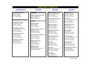
Right handend bracketRatchet wheel(teeth pointingupwards)Black tooth245/16” x 1-5/8”Lag screw5/16” -18 x 3/4”Carriage boltFlag angle5/16”Washer5/16” Hex nutSecuring Center Bracket Bushing AssemblyTools: Power drill, 3/16” Drill bit, 7/16” Socket driver, Step ladder, LevelIMPORTANT: <strong>TorqueMaster</strong> ® spring tube must be level before securing centerbracket bushing assembly to header.To locate the center bracket bushing assembly, mark the header halfway between the flagangles and level the <strong>TorqueMaster</strong> ® spring tube. Drill 3/16” pilot holes into header for the lagscrews. Fasten the center bracket bushing assembly to the header using (2) 5/16” x 1-5/8”lag screws.Center bracketbushing assembly25<strong>TorqueMaster</strong> ®spring tube(2) 5/16” x 1-5/8”Lag screwsSecuring Door For Winding Spring(s)Tools: Vice ClampsWith the door in the fully closed position, place vice clamps onto both vertical tracks justabove the third track roller. This is to prevent the garage door from rising while windingsprings.WARNINGFailure to place vice clamps onto vertical track can allowdoor to raise and cause severe or fatal injury.26Vice clamps above third trackroller on both sides of doorVice clamps attached to innerand outer rail of vertical trackBottom section<strong>Lift</strong> Cable AdjustmentsTools: Locking pliers, Flat tip screwdriver, Step ladder, Tape measure,Pliers/ Wire cuttersremove all cable slack.Snug the set screw and then tighten an additional 1-1/2 turns. Measure approximately 6” ofcable and cut off excess cable. Insert end of the cable into the hole of cable drum. Repeat forleft hand cable drum assembly.IMPORTANT: Ensure the counterbalance lift cable is aligned and seated in thefirst and second grooves of the cable drum prior to winding springs.NOTE: Illustration shows the right hand cable drum assembly, left hand cable drum assemblyis symmetrically opposite.First andsecond grooves<strong>TorqueMaster</strong> ®spring tube27Cam peakpointing straight upCut cable here6”Insertcable hereSet screwCounterbalancelift cableWinding SpringsTools: Ratchet wrench, 5/8” Socket, 3” Socket extension, Pliers/ Wirecutters, Flat tip screwdriver, Step ladderWARNINGIt is recommended that leather gloves be worn while windingsprings. Failure to wear gloves may cause injury to hands.Double check to ensure the counterbalance lift cable is aligned in the first and secondgrooves of the cable drum, see step <strong>Lift</strong> Cable Adjustments. There are two methods forcounting the spring turns as you wind. One method is to identify the black tooth on theratchet wheel inside of the end bracket. When the wheel makes one revolution and the toothreturns to its starting point, one turn has been made. The other method is to make a mark onthe winding shaft (or socket) and end bracket, and count your turns in this manner.Starting on the right hand side, turn the pawl knob on the end bracket to the upper position.Using a ratchet wrench with a 5/8” socket and a 3” extension, wind the spring by rotating thewinding shaft counter clockwise, while watching either the black tooth on the ratchet wheelor the mark on the winding shaft.NOTE: A 3” extension is recommended for added clearance from the horizontal track angle.IMPORTANT: Pawl knob must be in upper position to add / remove requirednumber of spring turns.After 2 to 3 turns, remove the ratchet wrench and adjust the counterbalance lift cable on theleft side. Ensure counterbalance lift cables are in the first and second grooves of the cabledrums, as shown in step <strong>Lift</strong> Cable Adjustments.NOTE: Single spring applications require no spring winding on the left hand side, but liftcable tension needs to be adjusted.IMPORTANT: Counterbalance lift cable tension must be equal on both sidesprior to fully winding springs.See the Winding Spring Turn Chart for the required number of winding turns:For single spring applications:Return to the right hand end bracket and continue winding the spring to the required numberof turns for your door. Place pawl knob in lower position.For double spring applications:Either use the black tooth on the ratchet wheel for winding reference or place a mark on thewinding shaft and end bracket. Place the ratchet wrench with 5/8” socket and a 3” extensiononto the left hand winding shaft end. To wind the spring, rotate the winding shaft clockwise,while watching the black tooth on the ratchet wheel or the mark on the winding shaft. Rotatethe winding shaft to the required number of winding turns for your door. Then return to theright hand side and wind the right hand spring to the required number of turns. Place pawlknob in lower position on both sides.Important: Mark the number of spring turns onto the end bracket warningtag.Note: Since total turns to balance door can deviate from winding spring turn chart valuesby ± 1/2 turn, adjustments to the recommended number of turns may be required after rearback hangs are installed.Starting on the right side, adjust the cable drum assembly by rotating the drum until the setscrew faces directly away from the header. The position of the cam peak on the <strong>TorqueMaster</strong>® spring tube should be pointing straight up.Loosen the set screw no more than 1/2 turn. Ensure counterbalance lift cable is aligned andseated in the first and second grooves of the cable drum. Pull on the end of the cable to12Please Do Not Return This Product To The Store. Contact your local <strong>Wayne</strong>-<strong>Dalton</strong> dealer. To find your local <strong>Wayne</strong>-<strong>Dalton</strong> dealer,refer to your local yellow pages business listings or go to the Find a Dealer section online at www.<strong>Wayne</strong>-<strong>Dalton</strong>.com
WindingshaftEnd bracketMarksBlack toothon ratchetwheelMark the number ofspring turns onto theend bracket warning tag5/8”SocketRatchetwrench3”ExtensionWINDING SPRING TURN CHARTDOOR HEIGHTSPRING TURNS6’-0” 146’-3” 14-1/26’-5” 156’-6” 156’-8” 15-1/26’-9” 15-1/27’-0” 167’-3” 16-1/27’-6” 177’-9” 17-1/28’-0” 1828Securing Drum WrapsTools: Step ladderPawl knob inlower positionPawl knob inupper positiontracks. Attach the horizontal tracks to the rear back hangs with 5/16”-18 x 1 hex bolts andnuts (may not be supplied). Horizontal tracks must be level and parallel with door within 3/4”to 7/8” maximum of door edge.NOTE: If an idrive ® opener is installed, position horizontal tracks one hole above level whensecuring it to the rear back hangs.WARNINGKeep horizontal tracks parallel and within 3/4” to 7/8” maximumof door edge, otherwise door could fall, resulting insevere or fatal injury.Important: Do not support the weight of the door on any part of the rearback hangs that cantilevers 4” or more beyond a sound framing member.Note: If rear back hangs are to be installed over drywall, use (2) 5/16” x 2” hex head lagscrews and make sure lag screws engage into solid structural lumber.Note: 26” angle must be attached to sound framing members and nails should not beused.Now, permanently attach the weatherstrips on both door jambs and header. The weatherstripswere temporarily attached in Preparing the Opening, in the pre-installation section ofthis manual.NOTE: When permanently attaching the weatherstrips to the jambs, avoid pushing the weatherstripstoo tightly against the face of door.Vice clampHorizontal tracks2nd Track rollerVice clampNOTE: If you don’t have drum wraps, then skip this step. Refer to Package Contents / PartsBreakdown, to determine if you have drum wraps.Starting on the left hand side, position the left hand drum wrap, as shown. Slide the left handdrum wrap over the cable drum assembly.IMPORTANT: Pull the counterbalance lift cable away from the header toclear the latch, while simultaneously sliding the drum wrap against the lastrib until the three catches engage the 3rd rib.Secure the hinge latch by rotating upward until a distinct snap is felt. Confirm the catch isfully engaged by lightly tugging on it. Repeat the same process for right hand side.Last ribDrum wrapCabledrum3 catches3rd rib3rd ribSound framingmembersCounterbalancelift cable. Pull toclear latch29Hinged latchRe-engagehinged latchRear Back HangsTools: Ratchet wrench, Socket: 1/2” 5/8”, Wrench: 1/2” 5/8”, (2) Viceclamps, Tape measure, Level, Hammer, Step LadderImportant: Hold the door down to prevent it from rising unexpectedly in theevent the spring(s) was over-wound and cautiously remove vice clamps fromvertical tracks.Raise the door until the top section and half of the next section are in the horizontal trackradius. Do not raise door any further since rear of horizontal tracks are not yet supported.WARNINGRaising door further can result in door falling and causesevere or fatal injury.Clamp a pair of vice clamps onto the vertical tracks just above the second track roller on oneside, and just below the second track roller on the other side. This will prevent the door fromraising or lowering while installing the rear back hangs.Using perforated angle (may not be supplied), (2) 5/16” x 1-5/8” hex head lag screws and(3) 5/16” bolts with nuts (may not be supplied), fabricate rear back hangs for the horizontal13Horizontaltrack5/16”-18 x 1-1/4”Hex bolt must extend into thetrack to serve as a roller stopPlease Do Not Return This Product To The Store. Contact your local <strong>Wayne</strong>-<strong>Dalton</strong> dealer. To find your local <strong>Wayne</strong>-<strong>Dalton</strong> dealer,refer to your local yellow pages business listings or go to the Find a Dealer section online at www.<strong>Wayne</strong>-<strong>Dalton</strong>.comPerforated angle boltedusing (2) 5/16” x 1-5/8”hex head lag screws toceiling member andparallel to door(3) 5/16” Bolts and nutsPerforated angle
Sound framingmembers3.) Check the distance between the flag angles, which must be door width plus 3-3/8” to3-1/2”.4.) Check the counterbalance lift cables for equal tension, adjust if necessary.5.) Rewind the spring(s).6.) Make sure door isn’t rubbing on jambs.Note: If an idrive ® opener was installed and you have completed this step, refer to theidrive ® Installation Instructions and Owner’s Manual to complete your idrive ® installation.Horizontaltrack(3) 5/16”Bolts and nutsPerforated angle5/16”-18 x 1-1/4”Hex bolt must extend into thetrack to serve as a roller stopPerforated angle boltedusing (2) 5/16” x 1-5/8”hex head lag screws toceiling member andparallel to doorWindingshaftPawlEnd bracketRatchet wheelRatchetwrench3”extension5/8” SocketPawlPawl knob inlower positionPawl knob inupper position3/4” To 7/8” 3/4” To 7/8”Door edgesHorizontal tracks30Balancing DoorTools: Ratchet wrench, Socket: 5/8”, 3” Socket extension, Wrench:5/8”, (2) Vice clamps, Tape measure, Level, Step LadderNote: Windows will cause the top section to be significantly heavier than the remainingsections. <strong>Wayne</strong>-<strong>Dalton</strong> attempts to balance the door at the top and bottom. To prevent anysudden door acceleration between the top and bottom, we recommend motor operating alldoors with windows. Doors with windows in the top section should not be manually operated.Remove any vice clamps. <strong>Lift</strong> the door and check its balance. Adjust spring(s) if door lifts byitself (hard to pull down) or if door is difficult to lift (easy to pull down). Anytime spring adjustmentsare made, ratchet pawl knob must be in the upper position. An unbalanced door cancause idrive ® or <strong>TorqueMaster</strong> ® <strong>Plus</strong> operation problems.Close the door and place vice clamps onto both vertical tracks just above the third trackroller. This is to prevent the garage door from rising while adjusting the counterbalancespring(s).IMPORTANT: To adjust springs, only add or remove a maximum of 3/10 ofa turn (three teeth on the ratchet wheel) at a time. Both sides need to beadjusted equally on double spring doors.Add spring tension: The ratchet wheel is made of 10 teeth. To add spring tension, ensurethe ratchet and socket is set so that it will tighten counter clockwise on the right hand sideand clockwise on the left hand side. Place the ratchet wrench with 5/8” socket and 3” socketextension onto the winding shaft, pull down to add 3/10 of a turn. Watch as three teeth of theratchet wheel pass over the pawl, creating three “clicks”.Remove spring tension: To remove spring tension, place a regular 5/8” wrench onto thewinding shaft. Pull down on the wrench to relieve pressure between the pawl and the ratchetwheel. Push in on the pawl to allow the three ratchet wheel teeth to pass by the pawl, as youcarefully allow the wrench to be rotated upward by the spring tension, release the pawl toallow it to engage with the ratchet wheel.Important: Be prepared to hold the full tension of the spring.Important: Do not add or remove more than 1 spring turns (1 spring turnequals 10 teeth on ratchet wheel) from the recommended number of turnsshown on the winding spring turn chart.If the door still does not operate easily, lower the door into the closed position, unwindspring(s) completely, and recheck the following items:1.) Check the door for level.2.) Check the <strong>TorqueMaster</strong> ® spring tube and flag angles for level and plumb.14Please Do Not Return This Product To The Store. Contact your local <strong>Wayne</strong>-<strong>Dalton</strong> dealer. To find your local <strong>Wayne</strong>-<strong>Dalton</strong> dealer,refer to your local yellow pages business listings or go to the Find a Dealer section online at www.<strong>Wayne</strong>-<strong>Dalton</strong>.com
Optional Installation<strong>TorqueMaster</strong> ® <strong>Plus</strong> Reset InstructionsTools: Ratchet wrench, 5/8” Socket, 3” Socket extension, 5/8” Wrench,(2) Vice clamps, Step ladderIMPORTANT: The drawbar operator force settings must be adjusted accordingto the manufacturer’s instructions. Some lighter weight doors are designedto operate with a single counterbalance spring. If that counterbalance springbreaks and the drawbar operator’s force settings are not adjusted accordingto the manufacturer’s specifications, the drawbar operator may then have thecapability of lifting the door to the open position, despite the broken counterbalancespring. This scenario will cause the counterbalance lift cables to goslack and engage the <strong>TorqueMaster</strong> ® <strong>Plus</strong> safety system. If a person is unawareof the slack counterbalance lift cables and the engaged <strong>TorqueMaster</strong> ® <strong>Plus</strong>safety system and activates the misadjusted drawbar operator, damage willlikely occur to the door and drawbar operator. The potential also exists thatthe person activating the drawbar operator under this scenario could beseverely injured.WARNINGRead these instructions carefully before attempting to reset the<strong>TorqueMaster</strong> ® <strong>Plus</strong> system. If in question about any of the procedures,do not perform the work. Instead, have a qualified doorsystems technician reset the system.WARNINGTo avoid severe or fatal injury, do not stand or walk under amoving door, or permit anyone to stand or walk under an electricallyoperated door.This door is equipped with a <strong>TorqueMaster</strong> ® plus system, a safety feature which prevents thedoor from rapidly descending in case of spring failure or forceful manual operation. If the systemengages with the door in the open position, personal items that are left unattended in the garageor home are at risk to theft. To ensure the safekeeping of these items, close the garage door.Typical signs of an engaged system.Single spring system: Visually inspect the <strong>TorqueMaster</strong> ® <strong>Plus</strong> right hand end bracket to confirmthat the system has engaged (see illustration). If the system is engaged, then the door willnot close. If the drawbar operator force settings were properly set during the initial installation,the door will not open. If the drawbar operator can physically overcome the weight of the doorand lift it to the open position, then the counterbalance lift cables will be slack. If the system isengaged, DO NOT attempt to make the repairs. Instead, have a trained door system technicianmake the necessary repairs to counterbalance lift cables, spring assemblies and other hardware.Double spring system: Visually inspect the <strong>TorqueMaster</strong> ® <strong>Plus</strong> end brackets to confirmthat the system has engaged (see illustration). Door will open, but will not close. Door makes adistinct “clicking” noise upon being opened. If the system is engaged, carefully follow the resetinstructions below or refer to the reset tag (attached to right hand end bracket) to reset the<strong>TorqueMaster</strong> ® <strong>Plus</strong> system.Resetting an engaged <strong>TorqueMaster</strong> ® <strong>Plus</strong> double spring system only:1. First, locate and visually inspect the <strong>TorqueMaster</strong> ® plus end brackets to confirm that thesystem has engaged (see illustration).2. Disengage the drawbar operator (if installed) by pulling or placing the emergency disconnectin the manually operated position.3. With assistance, raise the door to the fully open position.4. Place vice clamps onto both vertical tracks just below the bottom track roller on both sides.5. Now is a good time to remove vehicles or personal items from garage to provide clear accessto end brackets.6. Flip the ratchet pawl knob on both end brackets to the upper position (see illustration).7. Raise door 2”-3” and then lower door. Repeat this process until the system resets (seedisengaged system illustrations).IMPORTANT: Be prepared to support the total weight of the door.8. Cautiously remove the vice clamps from the vertical tracks. With assistance lower door.Checking springs for tension:9. Starting on the right hand side, place a ratchet wrench, 5/8” socket and a 3” extension on the<strong>TorqueMaster</strong> ® <strong>Plus</strong> winding shaft (see illustration). Ensure ratchet is set so that it will tightencounter clockwise on the right hand side, and clockwise on the left hand side. If tension is present,remove the ratchet and check the left hand side. If spring(s) have tension, the door will needto be balanced; refer to step, Balancing Door, to do this. If no spring tension is present, contact aqualified trained door system technician to replace the spring(s).IMPORTANT: To avoid possible injury, have a trained door systems technicianmake adjustments/ repairs to counterbalance lift cables, spring assembliesand other hardware.SideviewBelowviewRatchetpawlDrum wrap(if applicable)WindingshaftPawlDrumpawlEnd bracketRatchet wheel<strong>TorqueMaster</strong> ® <strong>Plus</strong>reset instructions tagCabledrumNo space between drum pawl andcable drum indicates engagementRatchetwrench3”extensionDoor Arm HookupTools: Needle nose pliers5/8” socketDrumpawlCabledrumSpace between drum pawl and cabledrum indicates non-engagementPawlPawl knob inlower positionPawl knob inupper positionAlign hole in the door arm with holes in drawbar operator bracket tabs, as shown. Insert 5/16”x 1-1/4” clevis pin, making sure hole in clevis pin is outside of second tab of drawbar operatorbracket. Insert hairpin cotter into clevis pin hole and spread hairpin cotter to secure assembly,as shown.5/16”x 1-1/4”Clevis pinDrawbaroperator bracketCotterpinDrawbar operatorbracket tabsDoor armInside LockTools: Power drill, 7/16” Socket driver, Tape measureClevis pinSpread cotter pinInstall the inside lock on the second section of the door. Secure the lock to the section with (4)1/4”-20 x 11/16” self drilling screws. Square the lock assembly with the door section, and alignwith the square hole in the vertical track. The inside lock should be spaced approximately 1/8”away from the section edge.Important: Inside lock(s) must be removed or made inoperative in the unlockedposition if an operator is installed on this door.Second section 1/8”Inside lockEnd capSquare hole invertical track(4) 1/4”-20 x 11/16”Self drilling screws15Please Do Not Return This Product To The Store. Contact your local <strong>Wayne</strong>-<strong>Dalton</strong> dealer. To find your local <strong>Wayne</strong>-<strong>Dalton</strong> dealer,refer to your local yellow pages business listings or go to the Find a Dealer section online at www.<strong>Wayne</strong>-<strong>Dalton</strong>.com
Pull Down RopeTools: Power drill, 1/8” Drill bit, Tape measureWARNINGDo not install pull down rope on doors with operators. Childrenmay become entangled in the rope causing severe or fatal injury.Measure and mark the jamb approximately 48” to 50” (1220 to 1270 mm) from floor on theright or left side of jamb. Drill 1/8” pilot hole for no. 6 screw eye. Tie the pull down rope to theno. 6 screw eye and to the bottom corner bracket, as shown.No. 6 Screw eyePull downrope48” to 50”From floorPull downropeBottom cornerbracket16Please Do Not Return This Product To The Store. Contact your local <strong>Wayne</strong>-<strong>Dalton</strong> dealer. To find your local <strong>Wayne</strong>-<strong>Dalton</strong> dealer,refer to your local yellow pages business listings or go to the Find a Dealer section online at www.<strong>Wayne</strong>-<strong>Dalton</strong>.com
MaintenanceCleaning Your Garage DoorImportant: Do not use a pressure washer on your garage door!While factory-applied finishes on garage doors are durable, it is desirable to clean them on aroutine basis. Some discoloration of the finish may occur when a door has been exposed todirt-laden atmosphere for a period of time. Slight chalking may also occur as a result of directexposure to sunlight.Cleaning the door will generally restore the appearance of the finish. To maintain an aestheticallypleasing finish of the garage door, a periodic washing of the garage door is recommended.The following cleaning solution is recommended:A mild detergent solution consisting of one cup detergent (with less than 0.5% phosphate) dissolvedinto five gallons of warm water will aid in the removal of most dirt.Note: The use of detergents containing greater than 0.5% phosphate is not recommended foruse in general cleaning of garage doors.Note: Be sure to clean behind weatherstrips on both sides and top of door.Caution: Never mix cleansers or detergents with bleach.Glass cleaning instructionsClean with a mild detergent solution (same as above) and a soft cloth. After cleaning, rinsethoroughly.Acrylic cleaning instructionsClean acrylic glazing with nonabrasive soap or detergent and plenty of water. Use your barehands to feel and dislodge any caked on particles. A soft, grit-free cloth, sponge or chamois maybe used to wipe the surface. Do not use hard or rough cloths that will scratch the acrylic glazing.Dry glazing with a clean damp chamois.Note: Do not use any window cleaning fluids, scouring compounds, gritty cloths or solventbasedcleaners of any kind.Painting Your Garage DoorPainting Instructions For Steel and Wood Doors.Steel (Surface Preparation for Painting)Wax on the surface must be removed or paint peeling/flaking will result. To remove this wax,it will be necessary to lightly scuff the surface with a fine steel wool pad, saturated with soapywater. A final wipe and rinse should be done with clean water only, to remove any loose particlesand any soapy film residue.Surface scratches, which have not exposed the metal substrate, can be lightly buffed or sandedwith 0000 steel wool or No. 400 sand paper to create a smoother surface. Care must be takento not expose the substrate under the paint. Once the substrate is exposed, the likelihood forrusting is greatly increased.If substrate is exposed, it must be treated to prevent rust from forming. Sand the exposed arealightly and paint with a high quality metal primer, specifically intended for galvanized surfaces,to protect the area from corrosion. Follow the drying time on primer can label before applyingtopcoat. The surface of the factory-applied finish, that is being painted, must not be too smooth,or the paint will not adhere to it. It is advisable to test in an inconspicuous area, to evaluateadhesion. If poor adhesion is observed, surface preparation for painting thefactory-applied finish,must be repeated until desired results are achieved. Again, care must be taken to not expose thesubstrate under the paint.Steel (Painting)After surface has been properly prepared, it must be allowed to dry thoroughly, then coatedimmediately with a premium quality latex house paint. Follow paint label directions explicitly. Oilbase or solvent base paints are not recommended. Please note that if substrate is exposed andnot properly primed, painting with latex paint may cause accelerated rusting of the steel in theexposed area.NOTES:1. Repainting of finish painted steel doors cannot be warranted, as this condition is totallybeyond the door manufacturer’s control.2. Consult a professional coatings contractor if in doubt about any of the above directions.3. Follow directions explicitly on the paint container labels for proper applications of coatings anddisposal of containers. Pay particular attention to acceptable weather and temperature conditionsin which to paint.Wood (Preparation and Painting)These instructions apply to all Wood Doors produced and sold by <strong>Wayne</strong>-<strong>Dalton</strong>. The exteriorsurfaces, as well as all edges must be properly painted and maintained if satisfactory performanceis to be achieved. The purpose for painting is to both protect and beautify the substrates.These requirements for finishing are intended to achieve both functions for reasonable servicelife of wood doors. Wood doors must be completely finished prior to installation, to ensure thatthe interior and exterior surfaces, as well as all edges of the doors are properly protected againstmoisture or other contaminants. Wood doors, in a non-finished condition, must not be transportedor stored where the wood surfaces can be exposed to moisture or other contaminants.Wood (Surface Preparation)Wood (Painting)Using painter’s tape, tape off all metal surfaces. A premium quality latex house based finishpaint is recommended for use over the factory latex based primerPainting the wood surfaces with at least 2 coats of finish paint over the primer. Follow paintmanufacture’s label directions completely for all coatings. Once finished, remove painter’s tapeand touch up where necessary.Wood (Maintenance and Refinishing)Yearly inspection of all the wood surfaces of the garage door(s) will reveal the extent of weatheringand the need for refinishing. When the finish becomes eroded or thin, clean and prime theareas of deterioration. Follow up with a complete refinishing of the door(s), according to theabove directions, as well as the manufacturer’s label directions. Protecting the door(s) fromprolonged exposure to moisture and sunlight is vital in extending the service life of your garagedoor(s).Operation and MaintenanceOPERATING YOUR GARAGE DOOR…Before you begin, read all warning labels affixed to the door and the installation instructions andowner’s manual. When correctly installed, your <strong>Wayne</strong>-<strong>Dalton</strong> door will operate smoothly. Alwaysoperate your door with controlled movements. Do not slam your door or throw your door into theopen position, this may cause damage to the door or its components. If your door has an electricopener, refer to the owner’s manual to disconnect the opener before performing manual dooroperation below.Manual door operation:For additional information on manual garage door operations go to www.dasma.com and referenceTDS 165.IMPORTANT: DO NOT PLACE FINGERS OR HANDS INTO SECTION JOINTS WHEN OPENINGAND/OR CLOSING A DOOR. ALWAYS USE LIFT HANDLES/ SUITABLE GRIPPING POINTS WHENOPERATING THE DOOR MANUALLY.Opening a Door: Make sure the lock(s) are in the unlocked position. <strong>Lift</strong> the door by using thelift handles/ suitable gripping points only. Door should open with little resistance.Closing a Door: From inside the garage, pull door downward using lift handles/ grippingpoint only or a high friction area only. If you are unable to reach the lift handles/ suitable grippingpoints only, use pull rope affixed to the side of door. Door should close completely with littleresistance.Using an electric opener:IMPORTANT: PULL ROPES MUST BE REMOVED AND LOCKS MUST BE REMOVED OR MADEINOPERATIVE IN THE UNLOCKED POSITION.When connecting a trolley type garage door opener to this door, an opener and/or trolley bracketmust be securely attached to the top section of the door, along with any u-bars provided withthe door. Always use the opener and/or trolley bracket supplied with the door. To avoid possibledamage to your door, <strong>Wayne</strong>-<strong>Dalton</strong> recommends reinforcing the top section on models 8000,8100, 8200 and 9100 doors with a u-bar (may or may not be supplied). The installation of theopener must be according to manufacturer’s instructions and force settings must be adjustedproperly. Refer to the owner’s manual supplied with your electric opener for complete details oninstallation, operation, maintenance and testing of the opener.MAINTAINING YOUR GARAGE DOOR…Before you begin, read all warning labels affixed to the door and the installation instructionsand owner’s manual. Perform routine maintenance steps once a month, and have the doorprofessionally inspected once a year. Review your Installation Instructions and Owner’s Manualfor the garage door. These instructions are available at no charge from <strong>Wayne</strong>-<strong>Dalton</strong>, A DivisionOf Overhead Door Corporation, P.O. Box 67, Mt. Hope, OH., 44660, or online at www.<strong>Wayne</strong>-<strong>Dalton</strong>.com. For additional information on garage door/opener maintenance go to www.dasma.com and reference TDS 151, 167 and 179.Monthly Inspections:1. Visual Inspection: Closely inspect jambs, header and mounting surface. Any wood found notto be structurally sound must be replaced. Inspect the springs, cables, rollers, pulleys, backhangs and other door hardware for signs of worn or broken parts. Tighten any loose screwsand/or bolts. Check exterior surface of the door sections for any minor cracks. Verify door hasnot shifted right and/or left in the opening. If you suspect problems, have a trained door systemtechnician make the repairs.WARNINGGARAGE DOOR SPRINGS, CABLES, BRACKETS, AND OTHER HARDWARE AT-TACHED TO THE SPRINGS ARE UNDER EXTREME TENSION, AND IF HANDLEDIMPROPERLY, CAN CAUSE SEVERE OR FATAL INJURY. ONLY A TRAINED DOORSYSTEMS TECHNICIAN SHOULD ADJUST THEM, BY CAREFULLY FOLLOWINGTHE MANUFACTURER’S INSTRUCTIONS.All surfaces must be clean, free of dust and dirt and any other contamination.17Please Do Not Return This Product To The Store. Contact your local <strong>Wayne</strong>-<strong>Dalton</strong> dealer. To find your local <strong>Wayne</strong>-<strong>Dalton</strong> dealer,refer to your local yellow pages business listings or go to the Find a Dealer section online at www.<strong>Wayne</strong>-<strong>Dalton</strong>.com
WARNINGNEVER REMOVE, ADJUST, OR LOOSEN THE BOLTS, SCREWS AND/OR LAGSCREWS ON THE COUNTERBALANCE (END OR CENTER BEARING BRACKETS)SYSTEM OR BOTTOM BRACKETS OF THE DOOR. THESE BRACKETS ARE CON-NECTED TO THE SPRING(S) AND ARE UNDER EXTREME TENSION. TO AVOIDPOSSIBLE SEVERE OR FATAL INJURY, HAVE ANY SUCH WORK PERFORMEDBY A TRAINED DOOR SYSTEMS TECHNICIAN USING PROPER TOOLS ANDINSTRUCTIONS.Torquemaster ® <strong>Plus</strong> Springs: Pawl knob(s) (located on the <strong>TorqueMaster</strong> ® end bracketsabove the door) should be engaged to prevent the door from rapidly descending in case ofspring failure or forceful manual operation.Torsion Springs: The torsion springs (located above the door) should only be adjusted by atrained door systems technician. DO NOT attempt to repair or adjust torsion springs yourself.Extension Springs: A restraining cable or other device should be installed on the extensionspring (located above the horizontal tracks) to help contain the spring if it breaks.2. Door Balance: Periodically test the balance of your door. If you have a garage door opener,use the release mechanism so you can operate the door by hand when doing this test. Start withthe door in the fully closed position. <strong>Lift</strong> the door to check its balance. Adjust Torquemaster ® orExtension spring(s), if door lifts by itself (hard to pull down) or if door is difficult to lift (easy topull down). DO NOT attempt to repair or adjust Torsion Springs yourself. To adjust Torquemaster ®or Extension spring(s), refer to your installation instructions and owner’s manual. If in questionabout any of the procedures, do not perform the work. Instead, have it adjusted by a trained doorsystems technician.3. Lubrication: The door should open and close smoothly. Ensure the door rollers are rotatingfreely when opening and closing the door. If rollers do not rotate freely, clean the door tracks, removingdirt and any foreign substances. Clean and lubricate (use a non-silicon based lubricant)hinges, steel rollers and bearings. DO NOT lubricate plastic idler bearings, nylon rollers, doortrack. DO NOT oil a cylinder lock, if actuation is difficult use a graphite dust to lubricate.18Please Do Not Return This Product To The Store. Contact your local <strong>Wayne</strong>-<strong>Dalton</strong> dealer. To find your local <strong>Wayne</strong>-<strong>Dalton</strong> dealer,refer to your local yellow pages business listings or go to the Find a Dealer section online at www.<strong>Wayne</strong>-<strong>Dalton</strong>.com
WarrantyLifetime Limited WarrantyModel 6100Subject to the terms and conditions contained in this Lifetime Limited Warranty, <strong>Wayne</strong>-<strong>Dalton</strong> (“Manufacturer”) warrants the steel sections of the door, which isdescribed at the top of this page, for as long as you own the door against:i) The door becoming inoperable due to rust-through of the steel skin from the core of the door section, due to cracking, splitting, or other deterioration of the steelskin, or due to structural failure caused by separation or degradation of the foam insulation.ii) Peeling of the original paint on the door as a result of a defect in the original paint or in the application of the original paint coating, in cases where the doorsections and the original paint: (a) have not been subjected to adverse atmospheric conditions or contaminates (such as salt water or other marine environment,or to toxic or abrasive substances, including those in the air); (b) have been maintained in compliance with Manufacturer’s recommendations; and (c) havenot been subject to physical abrasion, impacted by a hard object, or punctured (including without limitation “paint rub” occurring in metal to metal contact andmovement).The Manufacturer warrants the factory applied wood overlay of the above-described door, against defects in material and workmanship for a period of ONE (1)YEAR from the date of installation, provided all exterior surfaces and edges of the wood overlay are properly painted according to <strong>Wayne</strong>-<strong>Dalton</strong>’s Maintenance andPainting Instructions found in your Installations Instructions and Owner’s Manual. Bowing, checking and/ or cracking of the door overlay components is not considered adefect, but is an uncontrollable characteristic of wood.The Manufacturer warrants the garage door hardware (except springs) and the tracks of the above-described door, for as long as you own the door, againstdefects in material and workmanship, subject to all the terms and conditions below.The Manufacturer warrants those component parts of the door not covered by the preceding provisions of this Lifetime Limited Warranty against defects inmaterial and workmanship for a period of ONE (1) YEAR from the date of installation.The Manufacturer warrants the factory-applied finish and the factory attached Decatrim against fading and cosmetic changes from the time of installation forTWO (2) YEARS. If the sectional steel portion of door is re-stained or re-painted, the TWO (2) YEARS warranty for the factory-applied finish is void. The Model 6100factory attached Decatrim is warranted against warping, peeling, chalking, or delamination from the time of installation for TWO (2) YEARS.After a period of TWENTY (20) YEARS, from time of installation, replacement of Lifetime Limited Warranty materials will be pro-rated at 50 per cent of Manufacturer’spublished list pricing at time of claim, and you must pay this amount.This Limited Warranty is extended only to the person who purchased the product and continues to own the premises (where the door is installed) as his/herprimary residence (“Buyer”). This Limited Warranty does not apply to residences other than primary, or to commercial or industrial installations, or to installations onrental property (even when used by a tenant as a residence). This Limited Warranty is not transferable to any other person (even when the premises is sold), nor does itextend benefits to any other person. As a result this Limited Warranty does NOT apply to any person who purchases the product from someone other than an authorized<strong>Wayne</strong>-<strong>Dalton</strong> dealer or distributor.The Manufacturer will not be responsible for any damage attributable to improper storage, improper installation, or any alteration of the door or its components,abuse, damage from corrosive fumes or substances, salt spray or saltwater air, fire, Acts of God, failure to properly maintain the door, or attempt to use the door, itscomponents or related products for other than its intended purpose and its customary usage. This Limited Warranty does not cover ordinary wear. This Limited Warrantywill be voided if the original finish is painted over, unless Manufacturer’s preparation and painting instructions are followed explicitly. This Limited Warranty will bevoided if any holes are drilled into the door, other than those specified by the Manufacturer.THIS LIMITED WARRANTY COVERS A CONSUMER PRODUCT AS DEFINED BY THE MAGNUSON-MOSS ACT. NO WARRANTIES, EXPRESS OR IMPLIED (INCLUD-ING BUT NOT LIMITED TO THE WARRANTY OF MERCHANTABILITY OR FITNESS FOR A PARTICULAR PURPOSE) WILL EXTEND BEYOND THE TIME PERIOD SET FORTH INUNDERSCORED BOLD FACE TYPE IN THIS LIMITED WARRANTY, ABOVE.• Some States do not allow limitations on how long an implied warranty lasts, so the above limitations may not apply to you.Any claim under this Limited Warranty must be made in writing, within the applicable warranty period, to the dealer from which the product was purchased. Unlessthe dealer is no longer in business, a written claim to the Manufacturer will be the same as if no claim had been made at all.At the Manufacturer’s option, a service representative may inspect the product on site, or Buyer may be required to return the product to the Manufacturer atBuyer’s expense. Buyer agrees to cooperate with any representative of the Manufacturer and to give such representative full access to the product with the claimeddefect and full access to the location of its installation.If the Manufacturer determines that the claim is valid under the terms of this Limited Warranty, the Manufacturer will repair or replace the defective product. Thedecision about the manner in which the defect will be remedied will be at the discretion of the Manufacturer, subject to applicable law. THE REMEDY WILL COVER ONLYMATERIAL. THIS LIMITED WARRANTY DOES NOT COVER OTHER CHARGES, SUCH AS FIELD SERVICE LABOR FOR REMOVAL, INSTALLATION, PAINTING, SHIPPING, ETC.Any repairs or replacements arranged by Manufacturer will be covered by (and subject to) the terms, conditions, limitations and exceptions of this Limited Warranty;provided, however, that the installation date for the repaired or replaced product will be deemed to be the date the original product was installed, and this LimitedWarranty will expire at the same time as if there had been no defect. If a claim under this Limited Warranty is resolved in a manner other than described in the immediatelypreceding paragraph, then neither this Limited Warranty nor any other warranty from the Manufacturer will cover the repaired or replaced portion of the product.THE REMEDIES FOR THE BUYER DESCRIBED IN THIS LIMITED WARRANTY ARE EXCLUSIVE and take the place of any other remedy. The liability of the Manufacturer,whether in contract or tort, under warranty, product liability, or otherwise, will not go beyond the Manufacturer’s obligation to repair or replace, at its option, asdescribed above. THE MANUFACTURER WILL NOT UNDER ANY CIRCUMSTANCES BE LIABLE FOR SPECIAL, INCIDENTAL, OR CONSEQUENTIAL DAMAGES, including (butnot limited to) damage or loss of other property or equipment, personal injury, loss of profits or revenues, business or service interruptions, cost of capital , cost ofpurchase or replacement of other goods, or claims of third parties for any of the foregoing.• Some States do not allow the exclusion or limitation of incidental or consequential damages, so the above limitation or exclusion may not apply to you.No employee, distributor, dealer, representative, or other person has the authority to modify any term or condition contained in this Limited Warranty or to grantany other warranty on behalf of or binding on the Manufacturer, and anyone’s attempt to do so will be null and void.Buyer should be prepared to verify the date of installation to the satisfaction of the Manufacturer.The rights and obligations of the Manufacturer and Buyer under this Limited Warranty will be governed by the laws of the State of Ohio, USA, to the extentpermitted by law.19Please Do Not Return This Product To The Store. Contact your local <strong>Wayne</strong>-<strong>Dalton</strong> dealer. To find your local <strong>Wayne</strong>-<strong>Dalton</strong> dealer,refer to your local yellow pages business listings or go to the Find a Dealer section online at www.<strong>Wayne</strong>-<strong>Dalton</strong>.com
Covered by one or more of the following Patents; 5,408,724; 5,409,051; 5,419,010; 5,495,640; 5,522,446; 5,562,141; 5,566,740; 5,568,672;5,718,533; 6,019,269; 6,089,304; 6,644,378; 6,374,567; 6,561,256; 6,527,037; 6,640,872; 6,672,362; 6,725,898; 6,843,300; 6,915,573;6,951,237; 7,014,386; 7,036,548; 7,059,380; 7,121,317; 7,128,123; 7,134,471; 7,134,472; 7,219,392; 7,254,868. Canadian: 2,384,936;2,477,445; 2,495,175; 2,507,590; 2,530,701; 2,530,74; 2, 2,532,824. Other US and Foreign Patents pending.Please Do Not Return This Product To The StoreContact your local <strong>Wayne</strong>-<strong>Dalton</strong> dealer. To find your local <strong>Wayne</strong>-<strong>Dalton</strong> dealer, refer to your local yellow pagesbusiness listings or go to the Find a Dealer section online at www.<strong>Wayne</strong>-<strong>Dalton</strong>.comThank you for your purchase.After installation is complete, fasten this manual near THE garage door.