EZ-Set Torsion Spring System
EZ-Set Torsion Spring System
EZ-Set Torsion Spring System

You also want an ePaper? Increase the reach of your titles
YUMPU automatically turns print PDFs into web optimized ePapers that Google loves.
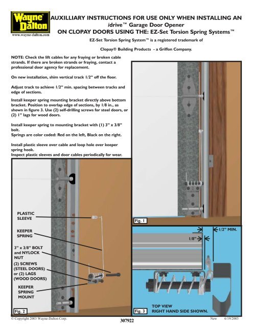
AUXILLIARY INSTRUCTIONS FOR USE ONLY WHEN INSTALLING ANidrive Garage Door OpenerON CLOPAY DOORS USING THE: <strong>EZ</strong>-<strong>Set</strong> <strong>Torsion</strong> <strong>Spring</strong> <strong>System</strong>sNOTE: Check the lift cables for any fraying or broken cablestrands. If there are broken strands or fraying, contact aprofessional door agency for replacement.On new installation, shim vertical track 1/2” off the floor.Adjust track to achieve 1/2” min. spacing between tracks andedge of sections.Install keeper spring mounting bracket directly above bottombracket. Position to overlap edge of sections, by 1/8 in., asshown in figure 3. Use (2) self-drilling screws for steel doors, or(2) 1” lags for wood doors.Install keeper spring to mounting bracket with (1) 3” x 3/8”bolt.<strong>Spring</strong>s are color coded: Red on the left, Black on the right.Install plastic sleeve over cable and loop hole over keeperspring hook.Inspect plastic sleeves and door cables periodically for wear.<strong>EZ</strong>-<strong>Set</strong> <strong>Torsion</strong> <strong>Spring</strong> <strong>System</strong> is a registered trademark ofClopay® Building Products - a Griffon Company.PLASTICSLEEVEFig. 1KEEPERSPRING3” x 3/8” BOLTand NYLOCKNUT(2) SCREWS(STEEL DOORS)or (2) LAGS(WOOD DOORS)KEEPERSPRINGMOUNT1/8”1/2” MIN.Fig. 2 Fig. 3307922TOP VIEWRIGHT HAND SIDE SHOWN.© Copyright 2003 Wayne-Dalton Corp. New 6/19/2003
NOTE: LONGER LEGS ON STANDARD BRACKETSTANDARDFig. 4MOUNTING BRACKET FOR CLOPAY DOORS USING THE:<strong>EZ</strong>-<strong>Set</strong> <strong>Torsion</strong> <strong>Spring</strong> <strong>System</strong>s1”1/8” HOLE1”Fig. 5Fig. 6Install idrive mounting plate supplied in supplemental installation bagin place of mounting plate supplied with the idrive operator shown infig. 4.Measure up 1 in. from the bottom of the CLOPAY <strong>EZ</strong>-<strong>Set</strong> <strong>Torsion</strong><strong>Spring</strong> <strong>System</strong>s mounting bracket and 1 in from the mounting surfaceof the bracket as shown in fig 5.Drill a 1/8” hole in the bracket at that pointRoute idrive Disconnect cable thru 1/8 in hole and then thru the slotin flag angle as shown in Fig. 6 & 7Return to idrive Installation manual for remaining instructions.Fig. 7