CATALOG 2012 - Whelen Engineering
CATALOG 2012 - Whelen Engineering
CATALOG 2012 - Whelen Engineering

You also want an ePaper? Increase the reach of your titles
YUMPU automatically turns print PDFs into web optimized ePapers that Google loves.
Lighting Regulations<br />
• ASTM Spec F2245-07, section A2 (LSA to be flown at night) must be met:<br />
- A2.6 Required Equipment<br />
• A2.6.2 Position lights as specified in A2.7.2<br />
• A2.6.3 An aviation red or aviation white<br />
anti-collision light system specified in A2.7.3<br />
• A2.7.3.6 Minimum Effective Intensities for Anti-Collision Lights<br />
Each Anti-Collision Light effective intensity must<br />
equal or exceed the applicable values in the following table.<br />
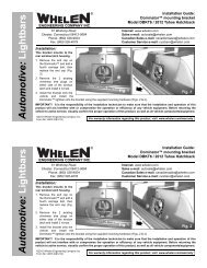
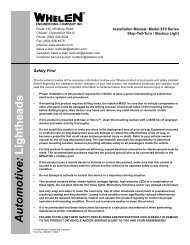
LIGHTING INSTALLATION LOCATIONS<br />
Wingtip: The major difference in systems is the location of the strobe power supplies which can be mounted locally, one in each wingtip, or a single power<br />
supply can be mounted in the fuselage. Installation time can be greatly reduced if done in conjunction with an annual or one hundred-hour inspection.<br />
Properly installed power supplies and cabling are necessary for the safe operation of <strong>Whelen</strong> or any light systems.<br />
Fuselage: Fuselage mounted units can be either self-contained with the power supply and lighthead as one unit, or remote lightheads run off a separate<br />
power supply. To meet the field of coverage, one must be on the top of the fuselage and one on the bottom.<br />
Vertical Fin: Finally, if applicable, a single anti-collision light can be mounted on the vertical stabilizer. It can be either a self-contained or remote lighthead<br />
depending on the aircraft.<br />
VERTICAL FIN<br />
One anti-collision strobe light<br />
mounted on the vertical fin will meet<br />
the minimum requirements on most<br />
aircraft. A half red and half white<br />
lens is recommended.<br />
WINGTIP<br />
LIGHTING TECHNOLOGY GLOSSARY<br />
Halogen Lamp:<br />
A halogen lamp is an<br />
incandescent lamp with a<br />
tungsten filament contained<br />
within an inert gas.<br />
Two wingtip strobe lights that<br />
protrude beyond the wingtip.<br />
Strobe Tube: Strobe light consist of a<br />
tube containing an inert gas, such as<br />
Xenon. Capacitors inside the light are<br />
charged up to a relatively high voltage,<br />
roughly 300 volts for small strobes,<br />
then discharged via a trigger to create<br />
a bright burst of light.<br />
An approved anti-collision<br />
strobe light system must<br />
project light 360° around<br />
the aircraft’s vertical axis.<br />
One or more strobe lights<br />
can be used.<br />
ANGLE ABOVE OR BELOW<br />
THE HORIZONTAL PLANE<br />
ENCLOSED WINGTIP<br />
Enclosed wingtip anti-collision strobe<br />
lights, require a third strobe light on<br />
the tail or vertical fin, to fill in the<br />
required light envelope. This is an<br />
approved anti-collision system.<br />
FUSELAGE<br />
In a fuselage mounted anti-collision<br />
strobe light system, a minimum of<br />
two strobe lights are necessary to get<br />
the required vertical coverage. This is<br />
an approved anti-collision system.<br />
LED: Led’s are solid state devices.<br />
These products operate on a<br />
square wavelength which creates<br />
higher visibility with longer on<br />
time. LED’s lifespan far outlive<br />
that of conventional halogen and<br />
strobe units.<br />
EFFECTIVE INTENSITY<br />
(CANDLES)<br />
0º to 5º 400<br />
5º to 10º 240<br />
10º to 20º 80<br />
20º to 30º 40<br />
30º to 75º 20<br />
An approved anti-collision<br />
strobe light system must<br />
project light + or - 30°<br />
above and below the horizontal<br />
plane of the aircraft.<br />
One or more strobe lights<br />
can be used. The + or -<br />
75° projected light is<br />
required since July 18,<br />
1977.
Q. HOW DO YOU CHOOSE A LIGHTING PACKAGE?<br />
A. CONSIDER WINGTIP OPTIONS:<br />
- Enclosed wingtip lighting configuration<br />
• A forward position light and anti-collision light are required.<br />
• Also a rear tail position light and anti-collision light will be<br />
required to comply with ASTM specifications for night<br />
flight operations.<br />
- End of wingtip light configuration<br />
• An all inclusive position, tail and anti-collision light may be<br />
utilized for compliance with the ASTM specifications for<br />
night flight operations.<br />
ADDITIONAL CONSIDERATIONS:<br />
- Landing & Recognition light options<br />
• Mounting locations (wingtip, cowling, landing gear)?<br />
• Size and shape restrictions (circular, rectangular or<br />
square, depth).<br />
- Strobe and power supply mounting locations<br />
• Wingtip (requires power supplies adjacent to each lighthead).<br />
• Cabin of aircraft (Single power supply to operate all<br />
lighthead assemblies).<br />
- Cable kit selections<br />
• What is the distance from your strobe tube to your<br />
power supply?<br />
• How many light assemblies do you need to connect?<br />
ALL NON-FAA APPROVED PARTS IN THIS <strong>CATALOG</strong> ARE SIGNIFIED BY A (—) IN THE APPROVALCOLUMN. PARTS WITHOUT FAA APPROVAL MAY STILL BE PUR-<br />
CHASED, HOWEVER, INSTALLATION OF THESE PARTS ON U.S. TYPE CERTIFICATED PRODUCTS WILL REQUIRE FAA APPROVALS.
STANDARD WINGTIP ENCLOSED WINGTIP<br />
Systems Recommendations<br />
! MAKERS OF AVIATION,<br />
AUTOMOTIVE AND INDUSTRIAL<br />
SAFETY LIGHTING SINCE 1953.<br />
WHELEN AVIATION WARNING<br />
PRODUCTS ARE ALL DESIGNED,<br />
ASSEMBLED, TESTED AND<br />
MANUFACTURED IN THE UNITED<br />
STATES OF AMERICA.<br />
SYSTEM RECOMMENDATIONS<br />
-Approved for night flight<br />
FOR AIRCRAFT WITH STANDARD WINGTIPS<br />
The most widely used system on the market, this provides all the components for<br />
anti-collison and position lights without the need for a taillight. The power supply is<br />
mounted in the fuselage and shielded cable is run to the strobe lights. The following<br />
is recommended:<br />
QUANTITY MODEL# PART# DESCRIPTION<br />
1 each HDACF 01-0770028-05 Power supply<br />
1 each 9034001 01-0790340-01 Wingtip strobe/LED position light, 14 VDC<br />
1 each 9034002 01-0790340-02 Wingtip strobe/LED position light, 14 VDC<br />
Note: Model A600PG1 and A600PR1 can replace Model 903400 for a LED solution<br />
1 each HD60 01-0750206-00 Installation package<br />
FOR AIRCRAFT WITH ENCLOSED WINGTIP FAIRINGS<br />
If the position and strobe lights are mounted under a clear fairing, a third tail strobe<br />
is required. The following is recommended:<br />
QUANTITY MODEL# PART# DESCRIPTION<br />
1 each HDACF 01-0770028-05 Power supply<br />
1 each 7111001 01-0771110-01 LED Wingtip light, 14 VDC, green<br />
1 each 7111002 01-0771110-02 LED Wingtip light, 14 VDC, red<br />
1 each A500AV14 01-0770024-00 Tail position/strobe light assembly<br />
1 each HDT390 01-0750205-00 Installation package<br />
Note: Model A650PG14/A650PR14 can replace Model 711100( ) for a strobe/halogen solution
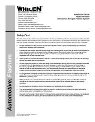
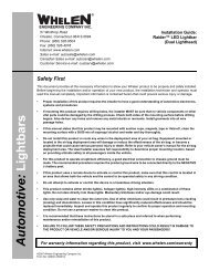
MicroBurst <br />
Series<br />
LED Wingtip & Tail lighting<br />
MICROBURST III - FORWARD & REAR FACING WINGTIP NAVIGATION LIGHT<br />
Weight . . . . . . . . . . . 0.21 lbs. (95gm)<br />
Dimensions . . . . . . . 1.5” (38mm) exp. H x 1.6” (41mm) W x 4.6 (116mm) L<br />
Available Colors. . . . Red, Green<br />
Current Draw . . . . . . 0.45 amps @ 14 VDC<br />
MODEL# PART# DESCRIPTION LENSES APPROVALS<br />
MB3R 01-0771507-020 Forward facing wingtip nav, with<br />
CometFlash ® 180º LED-Strobe and<br />
MB3G 01-0771507-010 rear facing white nav<br />
MICROBURST I - NAVIGATION TAILLIGHT<br />
Weight . . . . . . . . . . . 0.15 lbs. (68gm)<br />
Dimensions . . . . . . . 1.7” (43mm) H x 1.5 (38mm) Dia.<br />
Available Colors. . . . White<br />
Current Draw . . . . . . 0.45 amps @ 14 VDC<br />
Polycarbonate -<br />
MODEL# PART# DESCRIPTION LENSES APPROVALS<br />
MB2R 01-0771519-020<br />
MB2G 01-0771519-010<br />
Forward facing wingtip nav, with<br />
CometFlash 180º LED-Strobe<br />
Polycarbonate -<br />
MODEL# PART# DESCRIPTION LENSES APPROVALS<br />
MB1 01-0771490-000<br />
Microburst III<br />
MICROBURST II - FORWARD FACING WINGTIP NAVIGATION LIGHT<br />
Weight . . . . . . . . . . . 0.20 lbs. (90gm)<br />
Dimensions . . . . . . . 1.5” (38mm) exp. H x 1.6” (41mm) W x 4.6 (116mm) L<br />
Available Colors. . . . Red, Green<br />
Current Draw . . . . . . 0.40 amps @ 14 VDC<br />
Nav taillight with CometFlash 180º<br />
LED-Strobe. Utilizes same mounting as<br />
all <strong>Whelen</strong> Legacy assemblies<br />
Polycarbonate -<br />
Microburst II<br />
MICROBURST SERIES<br />
Microburst I<br />
!<br />
MicroBurst<br />
Highlights<br />
➤ Low current, long life,<br />
and light weight<br />
➤ Self-contained (no external<br />
power supply needed)<br />
➤ Sychronizable<br />
➤ Replaceable lenses<br />
are aerodynamic
VERTEX SERIES LED ANTI-COLLISION LIGHT ASSEMBLY<br />
Dimensions . . . . . . . 1” ( 25mm) H x 1-5/8” (41mm) Dia.<br />
Available Colors. . . . Red, White<br />
Current Draw . . . . . . 0.3 amps<br />
MODEL# PART# DESCRIPTION LENSES APPROVALS<br />
VTX609R N/A Red Anti-collision<br />
-<br />
polycarbonate<br />
VTX609C N/A Clear Anti-collision -<br />
Position/Anti-Collision Lighting<br />
71110 SERIES STROBE ANTI-COLLISION/LED POSITION LIGHT ASSEMBLY<br />
71110 Series is a Wingtip mounted strobe Anti-Collision/Position light assembly utilizing LEDs for the Forward Position lights. The LEDs provide a significant<br />
reduction in current draw over conventional position light bulbs. The strobe light lens assembly is radio shielded for maximum EMI/RFI protection.<br />
Direct replacement (exact footprint) for the <strong>Whelen</strong> model A650PG/PR series without replacing the current<br />
strobe power supply. Navigation light portion is wired with flying leads.<br />
Weight . . . . . . . . . . . 14 VDC 0.45 lbs. (204gm)<br />
28 VDC 0.50 lbs. (227gm)<br />
Dimensions . . . . . . . Exposed Height: 2.70” (69mm) 1.78” (45.21mm) x 3.88” (98.55mm)<br />
Available Colors. . . . Aviation Red, Aviation Green<br />
Current Draw . . . . . . 0.25 amps @ 14 VDC or 28 VDC<br />
MODEL# PART# DESCRIPTION LENSES APPROVALS<br />
7111001 01-0771110-01 Position Green, 14 VDC<br />
FAA TSO-C96a Class II / TSO-C30c Type II<br />
7111002 01-0771110-02 Position Red, 14 VDC<br />
Clear RFI coated<br />
glass: strobe<br />
FAA TSO-C96a Class II / TSO-C30c Type I<br />
7111003 01-0771110-03 Position Green, 28 VDC<br />
Clear polycarbonate:<br />
navigation lights<br />
FAA TSO-C96a Class II / TSO-C30c Type II<br />
7111004 01-0771110-04 Position Red, 28 VDC FAA TSO-C96a Class II / TSO-C30c Type I<br />
90340 SERIES STROBE ANTI-COLLISION/LED POSITION LIGHT ASSEMBLY<br />
90340 Series is an all inclusive wingtip mounted strobe Anti-Collision/Position light assembly utilizing LEDs for both the Forward & Tail Position lights,<br />
eliminating the need for a tail mounted position light. The LEDs provide a significant reduction in current draw over conventional position light bulbs.<br />
The strobe light lens assembly is radio shielded for maximum EMI/RFI protection. Direct replacement (exact footprint) for the <strong>Whelen</strong> Model A600PG/<br />
PR series without replacing the current strobe power supply. Single set of flying leads operates both Forward & Tail Nav on 28 VDC version, and one<br />
set each of flying leads for the Forward & Tail Nav on the 14 VDC version.<br />
Weight . . . . . . . . . . . 14VDC 0.60lbs. (272gm) / 28VDC 0.65lbs. (295gm)<br />
Dimensions . . . . . . . Exposed Height: 2.70” (69mm) x 1.87” (47.49mm)<br />
W x 5.69” (144.52mm) L<br />
Available Colors. . . . Aviation Red, Aviation Green<br />
Current Draw . . . . . . 0.5 amps @ 14 VDC / .25 amps @ 28 VDC<br />
MODEL# PART# DESCRIPTION LENSES APPROVALS<br />
9034001 01-0790340-01 Position Green Clear RFI coated glass on<br />
strobe. Clear polycarbon-<br />
FAA TSO-C96a Class II / TSO-C30c Types II & III<br />
9034002 01-0790340-02 Position Red ate on navigation lights FAA TSO-C96a Class II / TSO-C30c Types I & III<br />
POSITION & ANTI-COLLISION LIGHTING<br />
-- faa approved
71554 SERIES<br />
71554 Series in our newest LED Tail Position Light. Exact footprint for <strong>Whelen</strong> models A555A and 71011 taillights.<br />
Available in horizontal or vertical mount. Models -01 and -02 come with flying leads.<br />
Weight . . . . . . . . . . . 0.14 lbs. (64gm)<br />
Dimensions . . . . . . . Exp. Height: 1.4” (35.56mm) x 1.59” (40.38mm) W x 2.07” (52.57mm) L<br />
Available Colors. . . . Aviation White<br />
Current Draw . . . . . . 0.13 amps @ 28 VDC<br />
MODEL# PART# DESCRIPTION LENSES APPROVALS<br />
7155401 01-0771554-11 Horizontal mount, 14 VDC<br />
Clear Hardcoated<br />
FAA TSO-C30c Type III<br />
7155402 01-0771554-12 Vertical mount, 14 VDC<br />
Polycarbonate<br />
FAA TSO-C30c Type III<br />
A500A SERIES COMBINATION STROBE/TAIL NAVIGATION LIGHT<br />
A500A Series Combination Strobe/Tail Navigation Light is used when the wingtip anti-collision lights are mounted in an<br />
enclosure and can’t provide 360º of strobe coverage. It is a direct replacement for the standard tail position light. Available<br />
in a radio-shielded version. Voltage (14 or 28) and mounting (horizontal or vertical) must be specified when ordering.<br />
Weight . . . . . . . . . . . 0.3 lbs. (136gm)<br />
Dimensions . . . . . . . 1.7” (43mm H x 1.5” (38mm) Dia.<br />
Available Colors. . . . Aviation White<br />
Current Draw . . . . . . 14 VDC<br />
MODEL# PART# DESCRIPTION LENSES APPROVALS<br />
A500AV14 01-0770024-00 Vertical mount, 14 VDC<br />
FAA/PMA, FAA TSO-C30b<br />
A500AH14 01-0770024-02 Horizontal mountt, 14 VDC FAA/PMA, FAA TSO-C30b<br />
Glass<br />
A500AVD1 01-0770024-04 Vertical mount, radio-shieldedt, 14 VDC FAA/PMA, FAA TSO-C30b<br />
A500AHD1 01-0770024-06 Horizontal mount, radio-shieldedt, 14 VDC FAA/PMA, FAA TSO-C30b<br />
Power Supplies<br />
Q. How do you choose a power supply, and what is cometflash ®<br />
?<br />
A. The power supply needed depends on the application, and the<br />
mounting location. Model HDACF Series is a fuselage mounted power supply<br />
that will power two or three lights. Model A490ATSC Series is designed for<br />
installation adjacent to the strobe lighthead and will power one light assembly.<br />
Model A490TCF Series is the most economical power supply when<br />
adding only one light. It mounts adjacent to the strobe lighthead assembly<br />
(not legal for light output with Red strobe light). Most other <strong>Whelen</strong> power<br />
supplies are application specific, contact factory for details. Unless otherwise<br />
noted, all power supplies are CometFlash. <strong>Whelen</strong> <strong>Engineering</strong> is proud to<br />
have introduced the CometFlash CF, a major advancement in the field of<br />
safety lighting. By pulsing the flash tube four times in rapid succession, the<br />
effective “on-time” of the strobe is increased from 2/1000 of a second to 4/10<br />
of a second. This increases your airplane’s visibility. The development of the<br />
CometFlash reflects <strong>Whelen</strong>’s dedication to safety.<br />
POWER SUPPLIES<br />
...<br />
WHELEN ENGINEERING<br />
IS PROUD TO HAVE<br />
INTRODUCED THE<br />
COMETFLASH ®<br />
CF, A<br />
MAJOR ADVANCEMENT<br />
IN THE FIELD OF<br />
SAFETY LIGHTING.
STROBE POWER SUPPLY (NSN 6210-14456688)<br />
Model HDACF series provides simultaneous flashing, alternate flashing or both. It will operate one, two or three strobe lightheads. Operating the<br />
wingtip strobes in the alternating mode will provide an accumulated 42 joules of power to each light. When in the simultaneous mode, the accumulated<br />
power to each light is 21 joules. In the three light mode, the wingtips will flash simultaneous at an accumulated 21 joules each, they<br />
alternate with a third light operating at an accumulated 42 joules. On the trigger selector outlet, a switch mounted in place of the jumper will<br />
allow wingtip outlets 2 & 3 to be turned off, while the tail outlet 1 will remain on. This function is commonly used<br />
when the third light is for ground operations. This power supply will operate from 10 to 30 VDC.<br />
Weight . . . . . . . . . . . 2.1 lbs. (953gm)<br />
Dimensions . . . . . . . 2.37” (60mm) H x 5.0” (127mm) W x 5.50” (140mm) L<br />
Current Draw . . . . . . 7.0 amps @ 14 VDC / 3.5 amps @ 28 VDC<br />
MODEL# PART# DESCRIPTION APPROVALS<br />
HDACF 01-0770028-05 A413AHDACF power supply FAA/PMA<br />
A490ATSC STROBE POWER SUPPLY<br />
Model A490ATSC operates one strobe lighthead. Its compact size allows mounting in the wingtip and/or the tail,<br />
adjacent to the lighthead. It produces an accumulated 34 joules of power and can be equipped to flash<br />
simultaneously with up to 5 other like units by connecting an 18 gauge wire between outlet 3 on the input<br />
power connector. This power supply will operate from 10 to 30 VDC.<br />
Weight . . . . . . . . . . . 1.7 lbs. (771gm)<br />
Dimensions . . . . . . . 3.06” (78mm) H x 3.12” (79mm) W x 5.0” (127mm) L<br />
Current Draw . . . . . . 4.0 amps @ 14 VDC / 2.0 amps @ 28 VDC<br />
MODEL# PART# DESCRIPTION APPROVALS<br />
A490ATSC 01-0770062-03 A490ATSCF power supply FAA/PMA<br />
A490TCF SERIES STROBE POWER SUPPLIES (NSN 6130-10071195)<br />
A490TCF series operates one strobe lighthead. It is our most compact unit and can be mounted in the wingtip and/or the tail adjacent to the lighthead.<br />
It produces an accumulated 19 joules of power. It will only meet 400 CP when used with the A470A-W. This unit cannot be synchronized.<br />
This power supply operates from 10 to 30 VDC (not approved for use with red strobe light).<br />
Weight . . . . . . . . . . . 1.2 lbs. (544gm)<br />
Dimensions . . . . . . . 2.38” (60mm) H x 3.12” (79mm) W x 5.0” (127mm) L<br />
Current Draw . . . . . . 1.7 amps @ 14 VDC; 0.85 amps @ 28 VDC<br />
MODEL# PART# DESCRIPTION APPROVALS<br />
A490TCF 01-0770006-08 Standard unit, 20” leads, amp connectors FAA/PMA<br />
A490TCFM 01-0770006-14 20” leads, Molex connectors<br />
7000615 01-0770006-15 20” leads, no connectors<br />
POWER SUPPLIES<br />
-
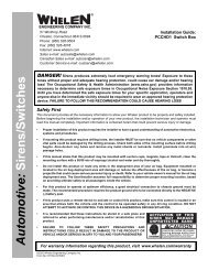
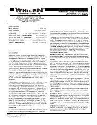
Parmetheus <br />
Series<br />
PARMETHEUS SERIES PAR-36 SUPER-LED ® LIGHTING<br />
Parmetheus PAR-36 Super-LED lights are a drop-in replacement for outdated halogen or HID lamps.<br />
The weight is virtually identical to the previous PAR-36 lamps. First FAA/PMA approved PAR-36<br />
Super-LED for aviation applications. And available in Landing and<br />
Taxi versions. Replacement Outer Lens: 68-3971486A30<br />
Weight . . . . . . . . . . . 0.6 lbs. (272gm)<br />
Dimensions . . . . . . . 4.38” Round x 1.75” Face to Screw terminal<br />
Available Colors. . . . White LED<br />
Current Draw . . . . . . .6 Amps @ 28 VDC / 1.2 Amps @ 14 VDC<br />
MODEL# PART# DESCRIPTION LENSES APPROVALS<br />
PLED1L 01-0771424-10 Landing (Spot Light, 10°)<br />
PLED1T 01-0771424-15 Taxi (Spreader Optic, 40°)<br />
Clear Hardcoated<br />
Polycarbonate<br />
PARMETHEUS SERIES PAR-46 SUPER-LED LIGHTING<br />
Parmetheus PAR-46 Super-LED lights are a drop-in replacement for outdated halogen or<br />
HID lamps. The weight is virtually identical to the previous PAR-46 lamps. <strong>Whelen</strong> TIR<br />
(Total Internal Reflector) technology, combining spot and flood optical combination,<br />
resulting in superior intensity and effectiveness. Available in Landing versions.<br />
Replacement Outer Lens: 68-3971577A30<br />
Weight . . . . . . . . . . . 0.6 lbs. (272gm)<br />
Dimensions . . . . . . . 5.65” Round x 2.25” Face to Screw terminal<br />
Available Colors. . . . White LED<br />
Current Draw . . . . . . 1.3 Amps @ 28 VDC / 2.6 Amps @ 14 VDC<br />
FAA/PMA<br />
MODEL# PART# DESCRIPTION LENSES APPROVALS<br />
PLED461L 01-0790623-10<br />
Landing Light<br />
PLED2L<br />
Landing (Spot Light, 10°<br />
Horizontal and 10° Vertical)<br />
Taxi Light<br />
PLED2T<br />
Clear Hardcoated<br />
Polycarbonate<br />
FAA/PMA<br />
Landing Light PLED461L<br />
Next to Outdated PAR-46 Halogen<br />
PAR-36 PAR-46<br />
PARMETHEUS SERIES<br />
!<br />
Parmetheus<br />
Highlights<br />
➤ Moisture resistant providing stable<br />
light output for thousands of<br />
trouble-free operating hours.<br />
➤ Power wiring attaches to brass<br />
screw terminals.<br />
➤ Assembly design includes<br />
clocking notch.<br />
➤ Polycarbonate, replaceable,<br />
hard-coated outer lens.<br />
➤ Metal, heat dissipating<br />
coated housing.<br />
➤ Low crrent and lightweight.
Landing, Taxi & Recognition Lights<br />
M2 ® LIGHTING<br />
M2 Super-LEDs provide unmatched high intensity lighting as well as low current consumption. The rear gasket insures<br />
that the lighthead and optional flange do not make contact with the aircraft’s surface. The lens and reflector are a sealed<br />
assembly, therefor mounting screws are placed outside of the lens reflector assembly, eliminating water infiltration. The<br />
unique lens shape is completely illuminated with patented Linear-LED designed reflector assembly. Updated<br />
design allows for ease of installation. Features multiple flash patterns for recognition functions.<br />
Dimensions . . . . . . . 2-1/2” (64mm) H, x 4” (102mm) W, x 1” (24mm) D<br />
Available Colors. . . . White LED<br />
Current Draw . . . . . . 0.45 amps<br />
MODEL# PART# DESCRIPTION LENSES APPROVALS<br />
71685 01-0771685-01 Landing Spot Light Clear Polycarbonate -<br />
71125 SERIES LED RECOGNITION LIGHT<br />
71125 series LED Recognition lights are designed to provide supplemental lighting for a wide variety of<br />
aircraft applications. Low current draw, low heat, long life and no EMI/RFI. Perfect for vibration prone areas.<br />
Several different beam spreads available. Designed to replace the <strong>Whelen</strong> A775 series. Item ships with flying<br />
leads. Version with an integrated MS connector also available. Can be used in conjunction<br />
with 71115 Flasher control assembly. Contact your OEM for installation information.<br />
Weight . . . . . . . . . . . 0.3 lbs. (136gm)<br />
Dimensions . . . . . . . 1.95” (50mm) H x 3.25” (83mm)<br />
W x 1.25” (32mm) D OVERALL<br />
Available Colors. . . . Aviation White<br />
Current Draw . . . . . . 0.9 amps @ 14 VDC<br />
MODEL# PART# DESCRIPTION LENSES APPROVALS<br />
7112510 01-0771125-10 10 degree beam pattern, 14 VDC<br />
7112511 01-0771125-11 20 degree beam pattern, 14 VDC<br />
7112512 01-0771125-12 90 degree beam pattern, 14 VDC<br />
71325 SERIES LED RECOGNITION LIGHT<br />
Clear Polycarbonate -<br />
Model 71325 is an LED Recognition/Exterior illumination product. It is an updated version of Model 71092<br />
recognition light (2008 Catalog). Model 71325 exceeds light output of 71092 three fold. Unit ships with 7<br />
inch wires into A447 style pin connector. Optimized for 28 VDC, will operate from 14-28VDC.<br />
Weight . . . . . . . . . . . 0.17 lbs. (77gm)<br />
Dimensions . . . . . . . 2.56” (65mm) W, x 1.38” (35mm) D, x 1.45”<br />
(37mm) H (Center to Center Mounting Holes)<br />
Available Colors. . . . Aviation White<br />
Current Draw . . . . . . .0.25 amps @ 28 VDC<br />
MODEL# PART# DESCRIPTION LENSES APPROVALS<br />
7132500 01-0271325-00 LED Recognition light Clear Polycarbonate -<br />
LANDING, TAXI & RECOGNITION LIGHTS
Miscellaneous<br />
FF25150 FLASHER<br />
MODEL# PART# DESCRIPTION APPROVALS<br />
FFS5150 N/A Recognition light, flasher module -<br />
OS INTERIOR LIGHT<br />
MODEL# PART# DESCRIPTION APPROVALS<br />
0SC0EDCR N/A White interior light with clear lens<br />
0AC0EDCR N/A<br />
White interior light with clear lens and 45º<br />
angled chrome-plated bezel<br />
INSTALLATION CABLE KITS (NSN 6080-14330778)<br />
Cable kits include all required connectors for hooking up the strobe light to the power supply. Warning<br />
placards and the Installation Service manual is included also. All cable is 16 gauge 3/C shielded.<br />
(Kits do not include switches or breakers)<br />
Cable diameter. . . . . 0.275” (7mm)<br />
Weight . . . . . . . . . . .0.050 lbs. per linear foot<br />
MODEL# PART# DESCRIPTION APPROVALS<br />
HS5 01-0750215-00 5’ Cable kit<br />
HT10 01-0750218-00 10’ Cable kit<br />
HS30 01-0750214-00 30’ Cable kit<br />
HD60 01-0750206-00 60’ Cable kit NSN<br />
HDT390 01-0750205-00 90’ Cable kit<br />
HT 01-0750216-00 Install kit only, no cable or connectors<br />
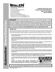
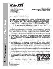
REPLACEMENT CONNECTOR KITS AND ASSEMBLIES FOR CABLES<br />
MODEL# PART# DESCRIPTION APPROVALS<br />
A441 01-0430011-00 3 Position male connector with pins kit<br />
A442 01-0410823-00 3 Position female connector with sockets kit<br />
A444 02-0230007-00 2 Position male connector with pins ass’y<br />
A446 02-0230085-00 2 Position female connector with sockets ass’y<br />
A447 01-0417808-00 4 Position male connector with pins<br />
A448 01-0417808-01 4 Position female connector with sockets<br />
-<br />
-<br />
-<br />
A442<br />
A448<br />
FLASHER & WIRING KITS<br />
A447<br />
A441<br />
A446<br />
A444
Distributed By:<br />
51 Winthrop Road<br />
Chester, Connecticut, 06412<br />
860-526-9504 • Fax 860-526-4078<br />
www.whelen.com<br />
©<strong>2012</strong> <strong>Whelen</strong> <strong>Engineering</strong> Company, Inc.<br />
<strong>Whelen</strong> <strong>Engineering</strong> reserves the right to upgrade<br />
and improve products without prior notice.<br />
Printed in the U.S.A. Code 12547B 11/12