90067-1 Seakeeper Model 21000 Gyro Installation Details
90067-1 Seakeeper Model 21000 Gyro Installation Details
90067-1 Seakeeper Model 21000 Gyro Installation Details
- No tags were found...

Create successful ePaper yourself
Turn your PDF publications into a flip-book with our unique Google optimized e-Paper software.
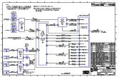
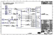
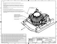
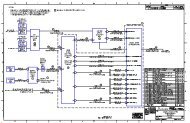
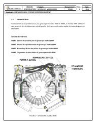
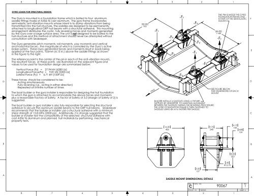
8 7 6 5 4 3 2 1FEGYRO LOADS FOR STRUCTURAL DESIGN:The <strong>Gyro</strong> is mounted in a foundation frame which is bolted to four aluminumsaddle fittings made of A356-T6 cast aluminum. The gyro frame incorporatessemi-elastic anti-vibration mounts whose intent is to damp vibrations from beingtransmitted into the hull structure. The saddles are designed to be permanentlyattached to longitudinal GRP hull beams with a structural adhesive. This mountingarrangement distributes the cyclic, fully reversing forces and moments generatedby the <strong>Gyro</strong> over a large surface area. The unit is not designed to be bolted to thehull structure and this method of attachment should never be attempted withoutconsultation with <strong>Seakeeper</strong>.The <strong>Gyro</strong> generates pitch moments, roll moments, yaw moments and verticaland horizontal forces - the magnitude of which is controlled by the <strong>Gyro</strong>’s activebrake system. These <strong>Gyro</strong> generated forces and moments result in loads beingapplied at the four points, 105mm (4.13 in.) above the saddle fittings as shownin the figure to the right.[30.00]762+Fz+Fx+Fy+Fz+Fx-Fz+FyTHIS PIN IS INSIDE THE GYROFOUNDATION FRAME ANDIS PART OF THE SEMI-ELASTICMOUNT[46.00]1168-FzFEThe reference point is the center of the pin in each of the anti-vibration mounts.The resultant forces at these points are illustrated on the adjacent figure andvalues to be used for foundation design are summarized below:-Fx+Fy+FyVertical Force (Fz) = 27.94 kN [6285 Lb]Longitudinal Force(Fx) = 9.81 kN [2205 Lb]Lateral Force (Fy) = 6.71 kN [1509 Lb]-FxDCThese forces should be considered to be:· Acting simultaneously· Fully reversing (i.e., acting in either direction)· Repeated an infinite number of timesThe boat builder or the gyro installer is responsible for designing the hull foundationto which the gyro is attached to accommodate the above forces and momentsplus a reasonable Factory of Safety. A Factor of Safety of 3.0 (Margin of Safety of 2) issuggested.The boat builder or gyro installer is also fully responsible for selecting the structuraladhesive to secure the aluminum saddle beams to the GRP hull beams. <strong>Seakeeper</strong>recommends that the builder or installer use a structural adhesive with a minimumshear strength of 13.8 MPa (2000 psi) . Additionally, it is strongly suggested that thebuilder or installer test the compatibility of the selected structural adhesive withcast A356 T6 aluminum and planned hull materials by performing mechanicalproperty tests.FWDBUILDER INSTALLS 4 SADDLES USING A FIXTURESUPPLIED BY SEAKEEPER TO MAINTAIN ALIGNMENTBETWEEN THE SADDLES DURING THE BONDING PROCEDURE.THE GYRO FOUNDATION FRAME IS THEN FASTENED TOSADDLES USING 8X M16 FASTERS PER SADDLE.SEE FIGURE BELOWFOR DIMENSIONS OF EACHMOUNTDC16.004069.752484.131054.88124BB8.00203.50R12.705.00127ASADDLE MOUNT DIMENSIONAL DETAILSASIZECDWG. NO.<strong>90067</strong>REV1876543SCALE: 1:10WEIGHT:21SHEET 5