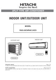
RAS-24C9/RAC-24C9 - Hitachi Air Conditioning Products
RAS-24C9/RAC-24C9 - Hitachi Air Conditioning Products
RAS-24C9/RAC-24C9 - Hitachi Air Conditioning Products
- No tags were found...

Create successful ePaper yourself
Turn your PDF publications into a flip-book with our unique Google optimized e-Paper software.
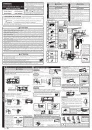
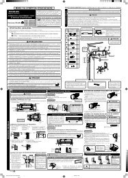
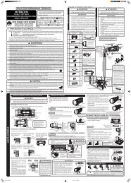
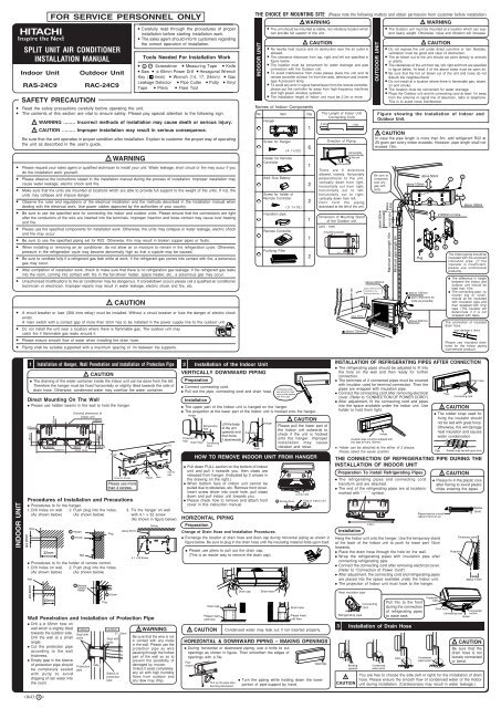
OUTDOOR UNIT● Please mount the outdoor unit on stable ground to prevent vibrationand increase of noise level.● Decide the location for piping after sorting out the different types ofpipe available.● Open the side plate by unscrewing the screws as shown below.!CAUTIONPlease face this side (suctionside) of the unit to the wall.Please remove side coverwhen connecting the pipingand connecting cord.Pull downwardPlease make sure to remove all spacers inside the unit.● Open the Top, Back and Side cover of the unit.● Pull out the spacers inside.(Spacers are only for transportation purpose).If not remove, vibration and noise will occur.Top coverBack coverSide coverINSTALLATION OF REFRIGERATING PIPES AND AIR REMOVAL1Preparation of Pipe● Use a pipe cutter to cut the copper pipe.● Jagged edge will cause leakage.● Point the side to be trimmed downwards during trimming to prevent copperchips from entering the pipe.● Before flaring, please put on the flare nut.2!OuterDiameter (mm)6.3515.88Pipe Connection!CAUTIONA (mm)Imperial flaring tool Rigid flaring tool0.8 ~ 1.5mm 0 ~ 0.5mm1.0 ~ 2.0mm 0 ~ 1.0mm● Please be careful when bending the copper pipe.● Screw in manually while adjusting the center. After that, use of torque wrench totighten the connection.WrenchDieCAUTIONSmall dia. sideLarge dia. sideValvehead capValve core capOuterdia.of pipe6.35 (1/4")15.88 (5/8")6.35 (1/4")15.88 (5/8")● Please use exclusivetoolIn case of removing flare nut of an Indoor unit, first remove a nutof small diameter side, or a seal cap of big diameter side will flyout. Prevent water from entering into the piping when working.Flare nutTorquewrenchCopper pipeDieSmall dia. sideLarge dia. sideACopper pipeTrimming toolTorque N·m(kgf · cm)13.7 – 18.6 (140 – 190)49 – 58.8 (500 – 600)19.0 – 21.0 (194 ~ 214)29.0 – 31.0 (296 ~ 316)9.0 (92)3AIR REMOVALRemoval Of <strong>Air</strong> From The Pipe And Gas Leakage Inspection1234Procedures of using Vacuum Pump for <strong>Air</strong> RemovalAs shown in right figure, remove the capof valve core. Then, connect the chargehose. Remove the cap of valve head.Connect the vacuum pump adapter tothe vacuum pump and connect thecharge hose to the adapter.Fully tighten the “Hi” shuttle of themanifold valve and completely unscrewthe “Lo” shuttle. Run the vacuum pumpfor about 10–15 minutes, then completelytighten the “Lo” shuttle and switch offthe vacuum pump.Completely unscrew the spindle of theservice valve (at 2 places) in anticlockwisedirection to allow the flow ofcoolant (using Hexagonal Wrench key).Remove the charge hose and tighten thecap of valve head. Check the cap’speriphery if there is any gas leakage.The task is then completed.Gas Leakage InspectionPlease use gas leakage detector to check if leakageoccurs at the connection of Flare nut as shown onthe right.If gas leakage occurs, further tighten the connectionto stop leakage.When the meter reaches - 101KPa(-76cmHg) during pumping, fullytighten the shuttle.Meter showing pressureClosedCharge hoseValveLoValveVacuum pumpadapterManifold valveVacuumpumpWhen pumping starts, slightly loosen theflare nut to check of air sucked in. Thentighten the flare nut.Cap of valve headHiThe body ofservice valveCap ofvalve coreHexagonalWrench KeyCap of valve headCONNECTION OF POWER CORD!WARNINGProcedures of WiringIn case that power is supplied from Indoor UnitLine CordAC 220-240V● THIS APPLIANCE MUST BE EARTHED.LNIndoorUnitOutdoorUnitIndoor UnitGRN + YELA B10mm10mm!Connecting CordPower line30mm10mm70mm10mm35mm25mmWARNINGStrip wiresOutdoor UnitGRN + YELA B● The naked part of the wire core should be 10 mm and fix it to the terminal tightly. Then try to pull theindividual wire to check if the contact is tight. Improper insertion may burn the terminal.● Be sure to use only power cables approved from the authorities in your country. For example in Germany:Cable type: NYM 3x1.5mm 2 , (fuse = 30A time delay)● Please refer to the installation manual for wire connection to the terminals of the units. The cabling mustmeet the standards of electrical installation.● There is a AC voltage of 220~240V between the L and N terminals. Therefore, before servicing, be sureto remove the plug from the AC outlet or switch off the main switch.2.0Wiring Of The Indoor Unit● For wire connection of the Indoor unit, you need to remove front panel and electrical cover.Method to remove front panel● Refer to “FINAL STAGE OF INSTALLATION – How to Remove The Front Cover”.Wiring of The Outdoor Unit● Please remove the side cover for wire connection.!WARNING● If you cannot attach the side cover due to the connecting cord, pressthe connecting cord in direction to the front panel to fix it.● Be sure that the hooks of the side cover is fixed in certainly. Otherwisewater leakage may occur and this causes short circuit or faults.● The connecting cord should not touch to service valve and pipes. (Itbecomes high temperature in heating operation.)Checking for the electric source and thevoltage range● Before installation, the power source must be checked and necessary wiringwork must be completed. To make the wiring capacity proper, use the wiregauges list below for the lead-in from a pole transformer and for the wiring froma switch board of fuse box to the main switch and outdoor unit in considerationof the locked rotor current.IMPORTANTCable lengthup to 16mup to 15mup to 25mMethod to remove electrical cover● Remove the screw and electrical cover.● Insert the connecting cord (A, B) from the bottom of unit.● Fixed the wire to terminal wires firmly as shown in figure at right side.ScrewAUTORESTARTSWITCHElectrical coverWire cross-section1.5mm 22.5mm 24.0mm 2AUTORESTARTSWITCHScrew● Investigate the power supply capacity and other electrical conditionsat the installation location.Depending on the model of room air conditioner to be installed,request the customer to make arrangements for the necessaryelectrical work etc.The electrical work includes the wiring work up the outdoor. Inlocalities where electrical conditions are poor, use of a voltageregulation is recommended.IMPORTANTFuse Capacity30A time delay fuseConnect theearth cordAfter remove thescrew and band,and put theconnecting cordsand fix the bandwith screw.ONOFFABABEarth terminal1Insulation And Maintenance Of Pipe Connection2Installation Of Remote ControllerHow to Remove The Front CoverHow to Attach the Front CoverFINAL STAGE OF INSTALLATION● The connected terminals should be completely sealed withheat insulator and then tied up with rubber strap.● Please tie the pipe and power line together with vinyl tape asshown in the figure showing the installation of Indoor andOutdoor units. Then fix their position with holders.● To enchance the heat insulation and to prevent watercondensation, please cover the outdoor part of the drain hoseand pipe with insulation pipe.● Completely seal any gap with putty.3Sleeve ofprotection pipePower Source And Operation TestPower SourceInsulation material for pipe connectionPutty!CAUTIONPutty● The remote controller can be placed in its holder which isfixed on wall or beam.● To operate the remote controller at its holder, please ensurethat the unit can receive signal transmitted from the controllerat the place where the holder is to be fixed. The unit will beepwhen signal is received from the remote controller. The signaltransmission is weaken by the fluorescent light. Therefore,during the installation of the remote control holder, pleaseswitch on the light, even during day time, to determine themounting location of the holder.The controller mustbe hooked onto thehook at the lowerpart of the holder.Push in the remotecontroller in thedirection as shownin figure below.Operation TestHolderRemoteController● Please ensure that the air conditioner is in normaloperating condition during the operation test.● Explain to your customer the proper operationprocedures as described in the user’s manual.●1 Remove the front panel.Please remove and attach thefront panel by both hands.● After opening the front panel by both hands.1 Undo the right arm while pushing it inside.2 Slide the front panel to right as shown in figure. Thenremove while pulling it to front.2 Remove the filters.3 Remove the caps and screwsat the lower portion of thefront cover.Cap4 Pull the front cover upward as faras the location where the lowerportion of the front cover is onthe deflector.2ScrewLower portion of front cover1Deflector1 After covering the front cover to the unit, certainly hook atthe upper portion (three places). Then, check that the drainpan is certainly attached. Push the center of front cover inthe direction of arrow.2 Fix the front cover at lower portion by screws and attachthe caps.3 Attach the front panel.HoleGuideShaft● Certainly insert the left shaft of the front panel to the holeof the front cover. Next insert the right shaft as same asthe left.4 Attach the filters which are placed the surface written“FRONT” up.●After attaching the filters, push the front panel at threearrow portion as shown in figure and close it.● Please use a new socket. Accident may occur due to the use of oldsocket because of poor contact.● Please plug in and then remove the plug for 2 – 3 times. This is toensure that the plug is completely plugged into the socket.● Keep additional length for the power cord and do not render theplug under external force as this may cause poor contact.● Do not fix the power cord with U-shape nail.5 Remove while pulling the front cover in direction to arrowas shown in figure to hold the both sides of front cover.