Backflow protection devices - Watts Industries
Backflow protection devices - Watts Industries
Backflow protection devices - Watts Industries
- No tags were found...

You also want an ePaper? Increase the reach of your titles
YUMPU automatically turns print PDFs into web optimized ePapers that Google loves.
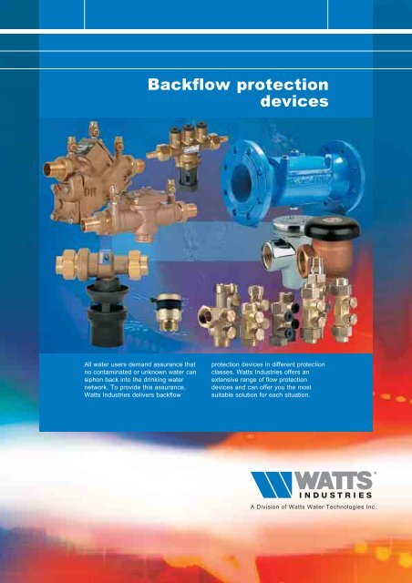
<strong>Backflow</strong> <strong>protection</strong><strong>devices</strong>All water users demand assurance thatno contaminated or unknown water cansiphon back into the drinking waternetwork. To provide this assurance,<strong>Watts</strong> <strong>Industries</strong> delivers backflow<strong>protection</strong> <strong>devices</strong> in different <strong>protection</strong>classes. <strong>Watts</strong> <strong>Industries</strong> offers anextensive range of flow <strong>protection</strong><strong>devices</strong> and can offer you the mostsuitable solution for each situation.
BACKFLOW PROTECTION DEVICESOUR EUROPEAN PRESENCE2H e a d q u a r t e r sM a n u f a c t u r i n g a n d s a l e sM a n u f a c t u r i n gS a l e s
BACKFLOW PROTECTION DEVICESCONTENTSINTRODUCTION PAGE 43PROTECTION MATRIX PAGE 6BA 909 DN 20 THROUGH DN 50 PAGE 7BA 909 DN 65 THROUGH DN 250 PAGE 9BA 009 PAGE 12BA BS MICRO PAGE 16CA 9C PAGE 17DA 288A PAGE 19EA & EB CHECK VALVES PAGE 20EA FC PAGE 23HA S8C/NF8 PAGE 25HD N9/NLF9 PAGE 26TERMS AND DEFINITIONS PAGE 27
BACKFLOW PROTECTION DEVICES4IntroductionThe possibility of pollution of drinking water pipelines is a risk not tobe overlooked. In fact, public opinion is very much aware of theproblem, especially after the increased information and concern in theecological field, which has led legislators to gradually adapt theEuropean standards.In this connection considerable resources have been invested intechnological research and manufacture of a range of equipment andaccessories designed to prevent pollution of the water in thedistribution systems.The European Ministry of Health have issued regulations and actsproviding local administrations and private individuals with preventiveand control measures against pollution of drinking water. There aretwo conditions which can give rise to a similar contamination:- contact between non-drinkable water and drinking water- risk of return of pollutants to the drinking water supplyThe EN 1717 is a <strong>protection</strong> method based on a classification of waterinto 5 liquids categories and a classification of pressure levels for theconnections between the drinking water network and one of theseliquids categories. Using these parameters, an installation matrix canbe drawn up. Projecting the installation matrix onto the <strong>protection</strong>matrix, which specifies the maximum level of <strong>protection</strong> for every<strong>protection</strong> device, provides the most adequate security.1. The installation matrixThe installation matrix offers a method for analysing an existingdrinking water installation, or one that must be designed, specifyinginformation regarding the nature of the connection and the possiblecontact. A coloured dot indicates the existence of the parameter.A white dot indicates that the parameter does not exist.2. The <strong>protection</strong> matrixThe <strong>protection</strong> matrix indicates the <strong>protection</strong> options for specific<strong>protection</strong> units, consisting of a <strong>protection</strong> device (e.g. the <strong>Watts</strong> CA9D or the <strong>Watts</strong> BA 009) and the requisite peripheral components,such as ball valves and filters. Obviously, each device has its ownmatrix (see page 6). A coloured dot indicates that security isguaranteed for the parameter for the relevant cell. A white dot meansthat such security is not guaranteed.3. Selecting equipmentIf an installation must be protected against backflow, an installationmatrix should be created for this installation. This enables one toselect the right <strong>Watts</strong> <strong>Industries</strong> equipment with the right securityfeatures for this particular installation. In so doing, you must ensurethat the coloured dot in the installation matrix is covered by a coloureddot in the <strong>protection</strong> matrix.Installation parametersP=atmP>atmHP=atm: Atmospheric pressureNo existing or possible reverse pressure from water column (H)or overpressure (P) directly downstream of the selectedinstallation point for the <strong>protection</strong> device.Back siphonage: when the pressure in the supply main is lowerthan the branch circuit; for example, owing to a break in thepiping or interruption in the drinking water supply.Liquids categoriesIn normal use fluids which are or canbe in contact with potable water areclassified in five categories asdefined below.In cases where insignificantconcentrations or substantialamounts of substances are present itmay be appropriate to redefine thesafety measurement.Category 1:Water to be used for humanconsumption coming directly from apotable water distribution system.Category 2:Fluid presenting no human healthhazard.Fluid recognised as being fit forhuman consumption, including watertaken from a potable waterdistribution system, which can haveundergone a change in taste, odour,colour or a temperature change(heating or cooling).Category 3:Fluid representing some humanhealth hazard due to the presence ofone or more harmful substances 1) .Category 4:Fluid presenting a human healthhazard due to the presence of one ormore toxic or very toxic substances 1)or one or more radioactive,mutagenic or carcinogenicsubstances.Category 5:Fluid presenting a human healthhazard due to the presence ofmicrobiological or viral elements.1)The border between category 3and category 4 is in principleLD 50 > 200 mg/kg body weight inreference to the EU Directive 93/21EEC dated April 27th, 1993.In the following tables on page 5 youwill find a few examples of liquidcategory classifications.P>atm: Existing or possible reverse pressure from water column(H) or overpressure (P) directly downstream of the selectedinstallation point for the <strong>protection</strong> device.<strong>Backflow</strong>: when a non drinkable water circuit, for example aheating system, a pressure is supplied greater than the mainsupply system feeding it.
BACKFLOW PROTECTION DEVICESDrinking water without additionsin the following situationscategoryWater from the public network 1Water under high pressure 1Cooled water 2Warm water 2Demineralised water 2Drinking water to be used as/for... categoryCooking food 2Washing produce and fruit 3Washing or pre-washing eating orcooking utensils 5Rinsing eating or cooking utensils 3Central heating water without additives 3Sewage and waste water 5Washing the body 5Washing clothing 5Water in the WC tank 3Drinking water for animals 5Swimming pool waterDrinking water with additives or water in contactwith liquids other than from category 1categorySoftened water (ion exchange) 2Water with anti-corrosive additives 3⁄4*Water with antifreeze 3⁄4*Water with liquid foodstuffs (juices, coffee,non-alcoholic drinks, soups) 2Water with alcoholic drinks 2Water with washing products 3⁄4*Water with disinfectants 3⁄4*Water with cleaning agents 3⁄4*Water with cooling agents 3⁄4** Depends on LD 505Pressure in case of any backflowLiquid categoryRisk of contamination*P = atmP > atm1 2 3 4 5 1 2 3 4 5* Indicate the risk of contamination by checking one of the circles.When doing this, please pay attention to the column in which the check marksare placed.- In column P = atm a check mark means that only the risk of siphoning backexists.- In column P > atm a check mark means that there is a risk of backflow.Always assume a fixed connection (Pc -situation) on the drinking waterinstallation.Installation matrixNote:In terms of the contactbetween drinking water andcontamination resulting fromsuch contact, it is assumedthat this connection ispermanent.Thus, when employing therisk analysis method, onemust always assume thesituation Pc(Permanent/Continual).The other two contactsituations (Pnc and T) are nolonger involved in the riskanalysis at this moment.
BACKFLOW PROTECTION DEVICESProtection matrix6BABA 909BA 009BA BS MICROPressureLiquid category<strong>protection</strong> units<strong>Backflow</strong> preventerwith controllablereduced pressurezoneP = atm P > atm1 2 3 4 5 1 2 3 4 5CACA 9CPressureLiquid category<strong>protection</strong> units<strong>Backflow</strong> preventerwith differentnon controllablepressure zonesP = atm P > atm1 2 3 4 5 1 2 3 4 5DADA 288APressureLiquid category<strong>protection</strong> unitsIn line anti-vacuumvalveP = atm P > atm1 2 3 4 5 1 2 3 4 5EACONTROLLABLECHECK VALVESPressureLiquid category<strong>protection</strong> unitsControllableanti-pollutioncheck valveP = atmP > atm1 2 3 4 5 1 2 3 4 5EBPLASTICCHECK VALVESPressureLiquid category<strong>protection</strong> unitsNon-controllableanti-pollutioncheck valveP = atmP > atm1 2 3 4 5 1 2 3 4 5Only permitted for specific domesticapplications and as front <strong>protection</strong> fordomestic water installations (pattern inhome water meters)HAHA S8CHA NF8HDHD N9HD NLF9PressureLiquid category<strong>protection</strong> unitsHose unionanti-vacuum valveP = atmP > atm1 2 3 4 5 1 2 3 4 5
BACKFLOW PROTECTION DEVICESBA 909 DN 20 ( 3 ⁄4") through DN 50 (2")The solution: BA 909 backflow protector with air supply to the intermediate zone,equipped with a KIWA certificate in conformance with KIWA inspectionguidelines BRL-K647.This solution means that now the BA 909, with KIWA certificate, can be used ineven more cases as the interruption alternative advised by water companies.7An attractive alternativeThe BA 909 does not use any energy and theacquisition costs are considerably lower thanthose for an interruption unit.The BA 909 is appropriate for backflow and backsiphoncross connections.Intermediate zoneBasic principleThe BA 909 backflow protector offers complete<strong>protection</strong> of the water supply network against thedanger of back-siphoning or backflow ofcontaminated water on the outlet side of thedevice. The BA 909 functions by maintaining apressure level in the middle chamber (reducedpressure zone) that is lower than that on theinflow side of the device (see also operation).Figure 1 depicts the most serious situation thatcan occur in practice:• there is reverse pressure on the outlet side• there is under-pressure on the inflow side• neither check valve closes completely as theresult of contamination.InletFirstcheckvalveRelief valveWater outAir inOutletSecond checkvalveIn this situation, under-pressure can also occur inthe middle chamber, making it difficult orimpossible for the backflow to be discharged.When this water reaches the first check valve, itcan even be siphoned back into the water supplynetwork. Thus, it is extremely important toprevent the occurrence of under-pressure in themiddle chamber. The BA 909 achieves this byallowing air into the chamber via a separatechannel that opens into the top of the chamber.A patent, U.S. patent no. 4.241.752 has beenawarded for this so-called air-in/water-outprinciple.Figure 1Pressure-TemperatureAppropriate for a maximum system pressure of 1000 kPa(10 bar) and for a maximum temperature of 60 °C. Forhigher temperatures a “hot water” model is available (max.90 °C) in dimensions from DN 20 through DN 50.MaterialsBronze body, plastic seats for the check valves, other partssuch as the relief valve with seat and stainless steel flangebolt, extended life rubber for the check valves and bronzetest valves.Further technical specifications upon request.DimensionsType Connection Dimensions Width Weightmm mm mm mm mm mm kgA B C D EBA 909 DN 20 3⁄4" 342 95 221 102 119 98 6.7BA 909 DN 25 1" 363 116 221 102 119 98 7.1BA 909 DN 32 1 1 ⁄4" 433 121 295 127 168 133 16.5BA 909 DN 40 1 1 ⁄2" 457 145 295 127 168 133 17.1BA 909 DN 50 2" 483 170 295 127 168 133 18.6BADEC
BACKFLOW PROTECTION DEVICES8OperationThe BA 909 backflow protector thatprovides air to the intermediate zone,provides complete <strong>protection</strong> of thewater supply network against thedanger of back-siphoning and/orbackflow of contaminated water.In part due to the air chamber, theBA 909 offers optimum <strong>protection</strong>based on the so-called air-in/water-outprinciple.kPa10090807060DN 2050 0 0.08 0.16 0.24 0.32 0.40 0.48 0.56 0.640 288 576 864 1152 1440 1728 2016 2304l/sl/hkPa100908070DN 2560Water flowThe first and the second check valveare opened so that water can flowthrough the device. The pressure in thewater supply network against thediaphragm of the relief valve keeps thevalve closed. The pressure in themiddle chamber is a minimum of50 kPa lower than the water pressure.Static stateBoth check valves are now closed.Because the pressure on the inlet sideis approximately 50 kPa higher thanthe pressure in the middle chamber,the relief valve is always kept closed.50 0 0.12 0.24 0.36 0.48 0.60 0.72 0.84 0.960 432 864 1296 1728 2160 2592 3024 3456kPa10090807060DN 3250 0 0.2 0.4 0.6 0.8 1.0 1.2 1.4 1.60 720 1440 2160 2880 3600 4320 5040 5760kPa10090807060DN 40l/sl/hl/sl/h50 0 0.3 0.6 0.9 1.2 1.5 1.8 2.1 2.40 1080 2160 3240 4320 5400 6480 7560 8640kPa10090l/sl/hcontamination807060DN 50Back-siphoningWhen the pressure in the water supplynetwork falls, both check valves close.The relief valve is opened and thewater from the middle chamber isdischarged via the water outlet. Thereis an atmospheric “interruption”between the water supply network andthe contaminated or unknown water atthe outlet side of the device.<strong>Backflow</strong>When downstream backflow occurs,the first check valve closes and thewater supply network is protectedagainst backflow. Simultaneously therelief valve opens and discharges aquantity of water, so that the pressurein the middle chamber remains lowerthan the pressure in the water supplynetwork. Because under normalcircumstances the relief valve does notpermit any water to flow through, waterescaping from the relief valve is also asignal that something is wrong. Whencontamination occurs in the first and/orsecond check valve, in case of reversepressure no backflow can take placebecause of the patented <strong>Watts</strong> airin/water-outprinciple.50 0 0.5 1.0 1.5 2.0 2.5 3.0 3.5 4.0 l/s0 1800 3600 5400 7200 9000108001260014400l/hApprovalsThe BA 909 backflow<strong>protection</strong> device has beencertified by Kiwa inconformance with BRL-K647.“Adjustable backflow<strong>protection</strong> <strong>devices</strong> for backsiphonor reverse pressurecross connections, combinedwith air flow to the reducedpressure zone”. The approvalhas been recorded in KIWAcertificate K 6086. The devicehas been tested and approvedin the U.S.A. by variousagencies including A.S.S.E.,A.W.W.A., C.S.A., U.C.F.,F.C.C.C.H.R. (California),S+A, U.L., U.P.C. and others.It has also been officiallycertified in various Europeancountries (such as NF, KIWAand SVGW).
BACKFLOW PROTECTION DEVICESBA 909 DN 65 through DN 250 (2 1 ⁄2"-10")Pressure - TemperatureAppropriate for a maximum system pressure of 1000 kPa (10 bar) and for amaximum temperature of 45 °C.9Material specificationsBody:Check valve seats:Test valves:Relief valve:Relief valve stem:cast iron with epoxy coatingbronzebronzebronze / cast iron with epoxy coatingstainless steelFurther technical specifications upon request.BA UnitAEDBCDimensionsType Dimensions Weight Material Flangesmm mm mm mm mm kg number Bolt Bolt holeof bolts x pitch diameterbolt thread (mm) (mm)A B C D E (mm)BA 909 DN 65 664 178 133 229 102 51 cast iron 4 x M 16 145 18BA 909 DN 80 664 178 133 229 127 51 cast iron 8 x M 16 160 18BA 909 DN 100 940 241 152 346 152 111 cast iron 8 x M 16 180 18BA 909 DN 150 1130 368 152 346 241 211 cast iron 8 x M 20 240 22BA 909 DN 200 1403 470 248 470 267 379 cast iron 8 x M 20 298 22BA 909 DN 250 1715 546 248 470 298 565 cast iron 12 x M 20 356 22Flange boring in conformance with DIN 2532.Measurements subject to change without notice.kPakPakPa90909080808070DN 657070DN 80 DN 100606060500 1.2 2.4 3.6 4.8 6.0 7.2 8.4 9.60 4320 8640 12960 17280 21600 25920 30240 3456050l/s 0 2 4 6 8 10 12 14 16l/h 0 7200 14400 21600 28800 36000 43200 50400 5760050l/s 0 3 6 9 12 15 18 21 24l/h 0 10800 21600 32400 43200 54000 64800 75600 86400l/sl/hkPakPakPa9090908080807060DN 150 DN 20070607060DN 250500 7 14 21 28 35 42 49 560 25200 50400 75600 100800 126000 151200 176400 20160050l/s 0 12 24 36 48 60 72 84 96l/h 0 43200 86400 129600 172800 216000 259200 302400 34560050l/s 0 20 40 60 80 100 120 140 160l/h 0 72000 144000 216000 288000 360000 432000 504000 576000l/sl/h
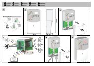
BACKFLOW PROTECTION DEVICES10InstallationThe BA 909 backflow protector must beinstalled so that it is easily accessiblefor maintenance and in order to verifythat it is operating properly.It must be installed horizontally with astrainer on the inflow side of the BA909, in such a way as to protect thevalves against unnecessarycontamination. Moreover, a shut-offvalve must be installed both upstreamand downstream of the device in thewater line. The overflow opening canbe connected to the drain via an airgaptundish set.If installed without a drain, the devicemust be installed at a height of aminimum of 2 x DN ≥ 20 mm above thesink hole. This may only be installedafter the pipe system has been cleanedin the normal method.Installation exampleInstalling two <strong>devices</strong> inparallel makes it possible toperform maintenanceproperly without disruptingthe water delivery.
BACKFLOW PROTECTION DEVICESAccessoriesAirgap tundish set 1717A type 1717 airgap tundish set can be used to mount a discharge pipe to therelief valve. This can be mounted directly to the body.The 1717 airgap tundish set is developed in conformance with NEN-EN 1717and EN 12729.The 1717 airgap tundish set can be easily connected to Ø 32 mm, 50 mm or75 mm discharges using PVC glue.11TK 9A Control SetThe control set consists of a pressure differential manometer with modifiedconnection hoses and nipples. Using this set, the installed protector can beregulated quickly and easily. The method described in the <strong>Watts</strong> TK9-AOperation and Control Methods Manual can be used as a guideline for this.BA <strong>Backflow</strong> <strong>protection</strong> <strong>devices</strong> must be checked regularly.ACBdifferentialpressure gauge00.250.5BAR0.751high pressure hose(yellow)lowpressurehose(red)(blue)shutoff valve4test valves123shutoff valve5OpenClosed
BACKFLOW PROTECTION DEVICESBA 009 DN 15 UP TO DN 8012Water companies demand assurance from all users that no contaminated orunknown water can siphon back into the drinking water network.To provide this assurance, <strong>Watts</strong> <strong>Industries</strong> provides backflow <strong>protection</strong> <strong>devices</strong>in different <strong>protection</strong> categories.The BA 009 series (DN 15 - DN 80) is just one of the many possible versions.InletIntermediate zoneSecurity of the drinking waterThe BA 009 backflow protectors withreduced pressure zone are speciallydesigned to prevent drinking watercontamination. They must be installedwhere there is a risk that contaminationcan occur due to back-siphoning orbackflow.<strong>Backflow</strong> can occur because, as theresult of a calamity, the pressure in anon-drinking water system temporarilyexceeds that of the main water supply.Back-siphoning can arise if the networkpressure falls below the originaldelivery pressure due to suddenextremely large consumption. In bothcases contaminated water can flowback into the drinking water network,with all the risks that such an evententails.OutletBasic principle of the BA 009(DN 15 - DN 80)The BA 009 <strong>protection</strong> device consistsof two check valves connected inseries, with a space between in whicha relief valve is installed. The deviceoperates by maintaining reducedpressure in this intermediate zone (seefigure). Even if there is reversepressure on the outlet side of thedevice and both check valves arecontaminated, the device preventscontaminated water from entering theline. In such a situation, the relief valvewill open and, in so doing, ensureatmospheric separation between thedrinking water and the user network.The figure depicts this situation.Product featuresEasy to disassemble check valves:The first check valve, the second checkvalve and the relief valve are all quitesimple to disassemble, which facilitatesmaintenance.Epoxy coating: The DN 65 & DN 80executions are coated with a highqualityepoxy.First check valveSecond check valveRelief valveBA 009 - pressure loss curvesDN 15DN 20DN 25DN 32DN 40DN 50DN 65DN 80
BACKFLOW PROTECTION DEVICESOperationTraffic flowThe first and the second check valveare open. The water pressure abovethe diaphragm of the relief valve keepsit closed. The pressure in the middlechamber is a minimum of 50 kPa lowerthan the outlet pressure.13Static state(no water being used)Both check valves are now closed.The pressure in the middle chamberremains 50 kPa lower than the outletpressure, which keeps the relief valveclosed.Back-siphoningWhen the pressure in the water supplynetwork falls, both check valves close.The relief valve is opened and thewater from the middle chamber isdischarged via the water dischargeoutlet.An atmospheric 'interruption' is createdbetween the water supply network andthe contaminated or unknown water onthe outlet side of the device.contamination<strong>Backflow</strong>If back-pressure arises on the outletside, reverse pressure is created andthe first check valve closes, the reliefvalve opens and a quantity of water isdischarged, so that the pressure in themiddle chamber remains lower thanthat in the water supply network.Because under normal circumstancesthe relief valve does not permit anywater to flow through, in addition toproviding security, the escape of waterthrough the relief valve serves as asignal that something is wrong.
BACKFLOW PROTECTION DEVICESTechnical information14Installation dimensions DN 15 through DN 50Installation dimensions DN 65 & DN 80C B AGHEHG470245205DIFType Art. no. A B C D E F G H IBA 009 DN15 405015010 45 50 95 35 110 205 G 1 ⁄2 14 138BA 009 DN20 405020010 45 45 80 60 140 305 G 3 ⁄4 14 225BA 009 DN25 405025010 45 45 80 60 140 305 G1 18 225BA 009 DN32 405032010 75 75115 90 225 455 G1 1 ⁄4 14 342BA 009 DN40 405040010 75 75115 90 225 455 G1 1 ⁄2 13 342BA 009 DN50 405050010 75 75115 90 235 470 G2 14 342115245Flange boring in conformance with DIN 2532.190InstallationThe BA 009 backflow protectors must be installedin such a way that they can be easily accessedfor maintenance and to verify proper operation.The device must be installed horizontally with astrainer on the inlet side, in such a way as toprotect the valves against unnecessarycontamination (see installation examples).Moreover, shut-off valves must be installedupstream and downstream of the device in thewater line.The relief opening can be connected to a drainvia an airgap tundish set.If installed without at drain, the <strong>devices</strong> must beplaced at a height of a minimum of 2 x DN ≥ 20mm above a sink hole. See installation examples.The device may not be installed until the pipesystem has been cleaned using the customarymethod.System specificationsMax. system pressureMax. water temperaturePN 1000 kPa (10 bar)60 °C (standard)90 °C (upon request)Material specifications DN 15 t/m DN 50Body:bronzeCheck valve seats: plasticRubber parts:siliconSeat relief valve:stainless steelMaterial specifications DN 65 & DN 80Body:cast iron with epoxy coatingFlange boring:in conformance withDIN 2532 PN 10Other: idem as DN 15 through DN 50ApprovalsThe BA 009 backflow <strong>protection</strong> device has been certifiedby KIWA in conformance with KIWA BRL-K646 (certificatenumber K 6117). The device has been tested and approvedin the USA by the following agencies: ASSA, AWWA,FCCCHR and IAPMO. It has also been certified in variousEuropean countries (such as NF, KIWA and SVGW).
BACKFLOW PROTECTION DEVICESInstallation examples<strong>Backflow</strong> protectorShut-off valve Type BA 009 Shut-off valveStrainer15<strong>Backflow</strong> protectorShut-off valve Type BA 009 Shut-off valveStrainer<strong>Backflow</strong> protectorShut-off valve Type BA 009 Shut-off valveStrainer
BACKFLOW PROTECTION DEVICES16BA BS MicroThe BS Micro backflow <strong>protection</strong>device is developed especially for lowflow rate applications. This uniqueprotector is used specifically in systemswith a low flow. The device isespecially appropriate for dental chairsand soap dispensers. The BS Microoffers optimum <strong>protection</strong> inconformance with liquids class 4.StandardsThe BA BS Micro was developed inconformance with EN1717.Installation guidelinesInstall the BA BS Micro inconformance with your nationalinstallation guidelines.BADimensionsPressure los curve36143Delta P[kPa]160140AA120110.510080ø32DN Model A6 BS006 1⁄8"8 BS008 1⁄4"10 BS010 3⁄8"60402000 0,2 0,4 0,6 0,8 1 1,2 1,4Flow (m 3 /h)BS006 BS008 BS010 EN 12729 DN6 EN 12729 DN8 EN 12729 DN10Putting the deviceinto operationPut the BS Micro intooperation by opening theshut-off valve up- anddownstream of the device.Then open the test cocks tobleed the device.After retightening the valves,the device is ready tooperate.Checking the deviceAccording to the nationalstandard, backflow <strong>protection</strong><strong>devices</strong> must be checked atleast once a year.InstallationInstall the BS Micro after cleaning the pipe system.To prevent contaminated water from flowing back into the potable water system,the BS Micro is installed upstream of the <strong>devices</strong>. Install the device in an easilyaccessible place: this simplifies inspections and maintenance.Ensure that the device is installed horizontally and is not under tension. Place astrainer on the inlet side of the device: this protects the valves againstunnecessary contamination. Moreover, shut-off valves are installed bothupstream of the strainer and downstream of the device. The discharge vent canbe connected to a drain via the integrated funnel.Material specificationsBodyBrass (DZR)Check valve PolymerSealingRubberSpringStainless steelFunnelPolymerTechnical specificationsConnection DN6 1⁄8"Connection DN8 1⁄4"Connection DN10 3 ⁄8"Lenght x height 143 mm x 110,5 mmOperating pressure PN 10Max. temperature 65 °CApprovalsDVGWNFOther approvals in progress
BACKFLOW PROTECTION DEVICESCA 9CThe CA 9C offers a simple and anefficient <strong>protection</strong> against pollution ofthe drinking water supply system.This <strong>protection</strong> device preventsbackflow of polluted water from flowingback into the drinking water supplysystem (fluid class 3). The CA 9C hasa double non-return valve constructionwith an intermediate relief valve andoffers <strong>protection</strong> with regard to backsiphoningas well as backflow.The CA 9C was especially developedfor smaller connections to the watersupply system.StandardizationThe CA 9C <strong>protection</strong> device has beendeveloped in conformity with EN1717.Installation instructionsInstall the CA 9C <strong>protection</strong> deviceaccording to national installationinstructions.CA17StrainerFirst check valveDiaphragmDischarge openingSeatSecond check valveWater flowThe pressure in the water supply network ensuresthat the diaphragm keeps the discharge openingclosed; then the first check valve is released fromthe diaphragm. The water flows to the secondcheck valve via the middle chamber and lifts itfrom its seat.Static stateBoth check valves are now closed. The dischargeopening is always held closed.Back-siphoningWhen the pressure in the water supply networkfalls, the second check valve closes against theseat. The first check valve closes against thediaphragm, the discharge opening opens to theintermediate zone, once enough overpressure iscreated. This creates an atmospheric"interference" between the water supply networkand the contaminated water downstream. If thecheck valve is contaminated, seepage isdischarged via the opening. This preventscontamination of the drinking water.
BACKFLOW PROTECTION DEVICESDimensionsPressure loss curve DN 15 and DN 2018Ø 40 mmDebit / debiet Flow mM 3 /H /hArticle number Item L H WeightA Ømm mm kg.407015290 CA 9C 1 ⁄2" bi x bi* 121 129 0,59407020290 CA 9C 3 ⁄4" bi x bi* 151 129 0,66* device is supplied incl. funnel setOperationYou can start to use the CA 9C byslowly opening the stop cock for theCA 9C.InspectionAccording to national standards a CAbackflow <strong>protection</strong> device must beinspected at least once a year.Functional testsIt is possible to test the CA 9C to seewhether it functions correctly.AssemblyAssemble the CA 9C after the water supply system has been cleanedin the prescribed way. Install the CA 9C in front of the dangerousappliance. This prevents polluted water from flowing back into thedrinking water system. Install the CA 9C horizontally and when thesystem is dead.The integrated filter on the inlet side of the device sees to it that thenon-return valves and relief valve are protected against unnecessarypollution. Regularly clean this filter.In conformity with the national installation instructions, a stop cock (1)with draining device (2) must be placed in front of the CA 9C. Therelief opening must be connected to a discharge pipe via the enclosedfunnel.12Material specificationsBody Brass (DZR)Spring Stainless steelSealing RubberFunnel PlasticTechnical specificationsDiameter nominal DN 15, DN 20Connection F 1 ⁄2", 3 ⁄4"Working pressure PN 10Max. temperature 65 °CConnection tundish Ø 40 mmApprovalsBELGAQUAKIWASVGWNFWRAS
BACKFLOW PROTECTION DEVICESDA 288A(C)Anti-siphon vacuum breakerAnti-siphon vacuum breakers prevent backflow caused by contaminated waterbeing siphoned back into the drinking water network.19DA 288AAnti-siphon <strong>devices</strong> with atmospheric vent prevent back caused by contaminatedwater being siphoned back into the drinking water network. One distinctivecharacteristic of these atmospheric vents is the lightweight valve, which isappropriate for temperatures up to 90 °C, that closes the vent opening, thuspreventing water from escaping.ApplicationDA 288A is also recommended for equipment withsmall tap capacities, such as lab equipment, forexample. In drinking water installations toequipment in which the water supply runs belowthe overflow level. In such a situation, the deviceis installed downstream of the shut-off valve, andis thus not under constant pressure.No shut-off device can be placed downstream ofthe DA.Advantages1. Silicon rubber seal2. Bearing3. Large flow-through for maximum capacity andminimum resistance4. Lightweight valveModel/dimensionsDA 288A connection sizes 1 ⁄4" through 3" in bronzeDA 288AC connection sizes 1 ⁄4" through 1" inchromed bronze (polished)CB1A24Max. pressure.: 10 barMax. temp.: 90 °CFurther technical specifications upon request.3Dimensionsmin.300 mmType Connection A B C Weightmm mm mm kgDA 288A(C) 1 ⁄4" 43 27 30 0.17DA 288A(C) 3 ⁄8" 43 27 30 0.17DA 288A(C) 1 ⁄2" 51 30 37 0.23DA 288A(C) 3 ⁄4" 57 38 41 0.51DA 288A(C) 1" 73 43 54 0.80DA 288A 1 1 ⁄4" 73 46 54 0.97DA 288A 1 1 ⁄2" 92 56 62 1.64DA 288A 2" 105 64 73 2.38DA 288A 2 1 ⁄2" 162 76 111 7.26DA 288A 3" 162 86 118 7.77
BACKFLOW PROTECTION DEVICES20EA & EB check valves<strong>Watts</strong> <strong>Industries</strong> brass and cast iron check valvesprevent back-siphoning of potable water or waterof unknown quality. The drain and regulationoptions allow you to check the operation of thedevice and its imperviousness to leaks withoutdisassembling the check valve. The brass andcast iron check valves can be applied inboth interior applications and other EAapplications.StandardizationThe controllable check valvesEA has been developed inconformity with EN 1717.Installation instructionsInstall the check valves EAaccording to nationalinstallation instructions.Special characteristicsKIWA, DVGW, NF and/or BELGAQUA approvalsComplies with the CEN-norm EN 13959Safety class EAVery low resistanceLong lifeHammer-free operationNoise-free operationMaterialsBodybrassPlugsbrass or plasticNutsbrassConnection unions brassCheck valve plasticSealrubber SBRPressure spring stainless steelModelThe check valve consists of:Brass body with test and drain portsNuts and connection unions, as requiredPlastic check valve moduleLipseal sealing principleSplit valve stemTechnical dataWidth range DN 15 - DN 65Connection sizes1⁄2" through 3" or 15 mmthrough 67 mmTest ports 1⁄4"Operational temperature 65 °C (max. 90 °C)Nominal pressure PN 10Max. operating pressure 1600 kPa (16 bar)Application areaLiquids:drinking waterEA check valvesType Nominal Connection sizes Total Approvals ifBt- Weightwidth length mark kgDN Inlet and outlet mmMU Chromed Male and female15 1⁄2" x 1 ⁄2" 47 KIWA 0.1020 3⁄4" x 3 ⁄4" 56 KIWA 0.17S Male to male15 3⁄4" x 3 ⁄4" 66 KIWA/DVGW/NF P-IX724/I 0.1220 1" x 1" 77 KIWA/DVGW/NF P-IX724/I 0.1725 1 1 ⁄4" x 1 1 ⁄4" 80 KIWA/DVGW/NF P-IX724/I 0.3732 1 1 ⁄2" x 1 1 ⁄2" 90 KIWA/DVGW/NF P-IX724/I 0.5540 2" x 2" 100 KIWA/DVGW/NF 0.8450 2 1 ⁄2" x 2 1 ⁄2" 115 KIWA/DVGW/NF 1.21PS Soldered connection unions15 connection unions Ø 15 97 KIWA/DVGW P-IX724/I 0.2420 connection unions Ø 22 120 KIWA/DVGW P-IX724/I 0.3525 connection unions Ø 28 128 KIWA/DVGW P-IX724/I 0.6732 connection unions Ø 35 148 KIWA/DVGW P-IX724/I 0.9540 connection unions Ø 42 166 KIWA/DVGW 1.5150 connection unions Ø 54 199 KIWA/DVGW 2.2765 connection unions Ø 67 225 3.42PU Male to female15 1⁄2" x 1 ⁄2" 137 KIWA/DVGW P-IX724/I 0.3020 3⁄4" x 3 ⁄4" 156 KIWA/DVGW P-IX724/I 0.4425 1" x 1" 169 KIWA/DVGW P-IX724/I 0.7832 1 1 ⁄4" x 1 1 ⁄4" 185 KIWA/DVGW P-IX724/I 1.1740 1 1 ⁄2" x 1 1 ⁄2" 202 KIWA/DVGW 1.7450 2" x 2" 241 KIWA/DVGW 2.6565 3" x 3" 125 1.57
BACKFLOW PROTECTION DEVICESEA check valvesType Nominal Connection sizes Total Approvals ifBt- Weightwidth length mark kgDN Inlet and outlet mmPI Female to female10 3⁄8" x 3 ⁄8" 101 KIWA/DVGW P-IX724/l 0.2715 1⁄2" x 1 ⁄2" 120 KIWA/DVGW P-IX724/I 0.3020 3⁄4" x 3 ⁄4" 120 KIWA/DVGW P-IX724/I 0.4425 1" x 1" 124 KIWA/DVGW P-IX724/I 0.6732 1 1 ⁄4" x 1 1 ⁄4" 160 KIWA/DVGW P-IX724/I 1.2340 1 1 ⁄2" x 1 1 ⁄2" 187 KIWA/DVGW 1.8550 2" x 2" 187 KIWA/DVGW 2.46WF Nut to male15 3⁄4" x 3 ⁄4" 88 KIWA/NF 0.1620 1" x 1" 92 KIWA/NF 0.2525 1 1 ⁄4" x 1 1 ⁄4" 113 KIWA/NF 0.4332 1 1 ⁄2" x 1 1 ⁄2" 115 KIWA/NF 0.6040 2" x 2" 120 KIWA/NF 0.8550 2 1 ⁄2" x 2 1 ⁄2" 135 KIWA/NF 1.50WH Nut to male15 3⁄4" x 3 ⁄4" 60 x 40 KIWA/NF 0.2220 1" x 1" 67 x 48 KIWA/NF 0.31FC Flange connector(60) 65 flanges PN 10 290 Belgaqua/DVGW/NF80 flanges PN 10 310 Belgaqua/DVGW/NF100 flanges PN 10 350 Belgaqua/DVGW/NFBigger sizes on requestKF Compression ends15 for pipe size 15 mm 90 KIWA 0.1620 for pipe size 22 mm 89 KIWA 0.22BB25 for pipe size 28 mm 92 KIWA 0.35Female to female15 1⁄2" x 1 ⁄2" 66 Belgaqua/NF 0.1320 3⁄4" x 3 ⁄4" 76 Belgaqua/NF 0.2025 1" x 1" 91 Belgaqua/NF 0.3532 1 1 ⁄4" x 1 1 ⁄4" 111 KIWA/Belgaqua/NF 0.6040 1 1 ⁄2" x 1 1 ⁄2" 121 KIWA/Belgaqua/NF 0.8050 2" x 2" 151 KIWA/Belgaqua/NF 1.50CC 55.1 Compression ends15 for pipe size 15 mm 140 KIWA 0.5020 for pipe size 22 mm 165 KIWA 0.75CCCompression ends15 for pipe size 15 mm 140 KIWA 0.4520 for pipe size 22 mm 165 KIWA 0.7055.1 Male to male15 1⁄2" x 1 ⁄2" KIWA/DVGW 0.5020 3⁄4" x 3 ⁄4" KIWA/DVGW 0.7025 1" x 1" KIWA/DVGW 1.3021
BACKFLOW PROTECTION DEVICESEB check valves22Type Flow Ø Total length Approvals WeightInch mm mm kgNN Male to female, chrome plated1⁄2" 15 1⁄2" x 1 ⁄2" 28 KIWA/BELGAQUA 0.053⁄4" 20 3⁄4" x 3 ⁄4" 33 KIWA/BELGAQUA 0.10NR Female to female, chrome plated1⁄2" 15 1⁄2" x 1 ⁄2" 30 KIWA/BELGAQUA 0.053⁄4" 20 3⁄4" x 3 ⁄4" 36 KIWA/BELGAQUA 0.09NW Female to female, chrome plated1⁄2" 15 3⁄4" x 1 ⁄2" 30 KIWA 0.07<strong>Watts</strong> <strong>Industries</strong> brass check valves resistance graphPressure differential [kPa]1001012345610,1 1 10 100 1000Volume flow [l/min]Global values, specific curves per valve available upon request.Line Check valveno. type1 BB015 KF0152 BB020 KF020 S015 WF0153 BB025 KF025 S020 WF0204 BB032 S025 WF025S032 WF0325 BB040 S040 WF0406 BB050 S050 WF050
BACKFLOW PROTECTION DEVICESEA FC controllable anti-pollution check valveThis flanged controllable Anti-Pollution Check Valve is dedicated to be installedas a <strong>Backflow</strong> Prevention Device (code EN1717:EA) in potable water installationsand other sanitary applications. This device can also be used in processes likedistribution networks and pump installations.23Benefits of the EA FC check valve:- Construction and performance in compliance with national standards andEuropean standard EN 13959- Compact construction- Standardized length- Modular check valve cartridge for fast and easy maintenance- No internal parts to be lost while replacing the cartridge- Low pressure loss- Ranging from DN 65 (DN60) up to DN 100 inclusive and according to DIN PN16(bigger sizes on request)Pressure loss curve FC065, FC080, FC100Delta P [kPa]454035302520Capacity [m 3 /h]1510500 20 40 60 80 100 120 140Flow [m 3 /h]CEN DN65 CEN DN80 CEN DN100 FC065 FC080 FC100
BACKFLOW PROTECTION DEVICES24Technical specificationsNominal flow 60 up to 250 mmOperating pressure max. 16 barTest pressure max. 24 barMax. temperature 65 °CMaterial specificationsBody / cover ductile iron GGG40Coating Epoxy Coated, RAL 5015Polymer parts PPO / PPRubber parts NBRApprovalsACSBelgaquaDVGWKIWANFWRASDimensionsACEDCVFBBCBGHArticle number Type DN CV A B C D E F G H308065361 FC065 (60) 65 CS100 290 G1/2 145 37.5 185 118 (135) 145 4 x 19308080361 FC080 80 CS100 310 G1/2 155 44 200 132 160 8 x 19308100361 FC100 100 CS100 350 G1/2 175 64 220 156 180 8 x 19
BACKFLOW PROTECTION DEVICESHA S8C/NF8 hose union backflow preventerAnti-siphon <strong>devices</strong> with atmospheric vent for hand-held showers and spigots forhose connections that are mounted downstream of the shut-off valve so that theyare not under continual pressure.25HA S8CHA S8C is an anti-siphon device with atmospheric vent forhand-held showers that are mounted downstream of theshut-off valve, so that they are not under continualpressure.311 2"Model: brass chrome plated (polished)Max. pressure: 10 barMax. temp.: 60 °C37Measurements subject to change without notice.Further technical specifications upon request.12"Operation321312321HA S8C in closed position.Valve 1 closes againstdiaphragm 2. Openings 3 tothe atmosphere are open.Before flow starts, openings3 are closed.Only then valve 1 opens.As the result of the loss ofpressure in the network,valve 1 closes againstdiaphragm 2, preventing anybackflow. Ports 3 areopened.HA NF8HA NF8 hose union backflow preventers are used with tapsfor hose connections and must be installed in a verticalposition. HA NF8 is constructed using a shear screw, whichmeans that it cannot be removed. When the ring is presseddown on the outside, in such a way as to prevent freezing ofthe tap and the atmospheric vent, the hose connected to itcan be tapped. This is mounted downstream of the shut-offvalve, and is thus not under continual pressure. Height >200 mm above the maximum downstream fluid level.Model:brassMax. pressure: 10 barMax. temp.: 60 °COperation: same as the HA S8CFurther technical specifications available upon request.383 4"3 4"51
BACKFLOW PROTECTION DEVICESHD N9/NLF9 hose union anti-vacuum valvecombined with a check valve26HD N9/NLF9, dual check valves with atmospheric vents with intermediateatmospheric connection.HD N9/NLF9HD N9/NLF9 prevents back-siphoning of contaminatedwater into the drinking water network and is appropriate forlaboratory use. HD N9/NLF9 must be installed vertically.The construction is identical to that of the HA S8C/NF8;however, a second check valve is installed on the outletside. HD N9 is appropriate for mounting under continualpressure. HD NLF9 is appropriate for mounting downstreamof the shut-off valve. The downstream piping, which is notunder constant pressure, must be flexible and detachable.31Model:HD NLF9 brass chrome plated (polished)HD N9 brassMax. pressure: 10 barMax. temp.: 60 °C2532Operation1. Static position, no waterflow.2. Water flow, both valvesare opened.3. Back-siphoning, bothvalves are closed.HD NLF9Connection sizes:HD NLF9: 3⁄8" female thread x 3 ⁄8" male threadHD N9: 1⁄4" female thread x 1 ⁄4" female threadHD N9: 3⁄8" female thread x 3 ⁄8" female threadH > 200 mmFurther technical specifications upon request.DischargeAfvoer
BACKFLOW PROTECTION DEVICESTerms and definitionsFor the purpose of this Europeanstandard, the following terms anddefinitions apply.Air break to drainThe unobstructed distance betweenthe low point of overflow, discharge ordrain of a device or installation,leading from a water apparatus, andthe top point of the device whichcollects this water.Air gapThe physical break between the lowestlevel of the water inlet and themaximum fault level or critical level ofan appliance or installation, a feedpipe, or an air inlet orifice incorporatedinto a hydraulic circuit.Air inletAn orifice designed to admit air fromthe atmosphere into a hydraulic circuit.offices, communal residences, etc.(for example kitchen sink, wash andhandbasin, bath, shower, WC,production of hot water for sanitarypurposes, domestic washing machineand dishwasher, bidet, watering ofgarden);- special uses relating to similarconsumers where products are usedwith low concentrations andpresenting no danger for humanhealth (for example authorised waterconditioning, air conditioning);- in industrial and commercialpremises “Domestic use” is limited towater used for thoseapplications/appliances describedunder normal use in dwelling andhomes (for example excludes waterused for process, fire fighting, centralheating or irrigation systems).DownstreamThe side to which fluid flows undernormal conditions.LD50The quantities of substancesor mixture which, given onone intake through oral andparental path, bring aboutwithin 15 days (the requiredtime to take into accountpotential delayed effect) thedeath of 50 out of 100treated animals.Non domestic useAll uses related to aprofessional activity withinindustry, trade, agriculture,health establishments, etc.All uses related to pricateand public swimming poolsand public baths.OverflowA means for dischargingnaturally excess fluid from anappliance when it hasreached a specified level.27Appliance, equipmentA device in which the potable water isused and/or is modified e.g. waterheater, chemical dosing unit, coffeemachine,WC-pan.<strong>Backflow</strong>Movement of the fluid fromdownstream to upstream within aninstallation.<strong>Backflow</strong> <strong>protection</strong> deviceA device which is intended to preventcontamination of potable water bybackflow.ContaminationResult of rendering impure by contactor mixture, to corrupt, defile, pollute,sully, taint or infect.DisconnectionBreak in a hydraulic circuit creating anatmospheric area between twoelements, one carrying or containingpotable water (upstream) and anothercarrying or containing another fluid(downstream).Domestic useAny use related to residential or similardwellings:- normal use for dwellings and homes,as well as hotels, schools andPotable water systemWater system located downstream ofthe delivery point specified by thewater supply authorities or regulations.Family of <strong>protection</strong>General identification of a backflow<strong>protection</strong> device principle.FluidAll substances which can be deformedby small forces. Fluids are divided intoliquids and gases.Liquid levelsCritical levelPhysical or piezometric level of theliquid reached in any part of theappliance 2 s after closing the waterinlet, starting from maximum faultlevel.Maximum operational levelIn an open system, this is themaximum level of the liquid. In apressurized system, this is themaximum piezometric height possible.Maximum fault levelThe highest physical or piezometriclevel of the liquid reached in any partof the appliance when it operatescontinuously under fault conditions asdescribed in product standard.Point of useThe point where water isdrawn by the user eitherdirectly or by connecting anapparatus.Pollution of potablewaterAny degradation of thequality of potable water.Protection pointLocation in a hydraulic circuitwhere a <strong>protection</strong> unit isinstalled.Protection unitA device or a device incombination with otherhydraulic components whichconstitutes the <strong>protection</strong>against backflow.Type of <strong>protection</strong>An identified operatingprinciple applied to a<strong>protection</strong> device belongingto a given family.UpstreamThe side from which fluidflows under normalcircumstances.The photos and description contained in this brochure are solely intended as an indication, <strong>Watts</strong> <strong>Industries</strong>reserves the right to make technical and design changes to its products without prior notice.
Product range <strong>Watts</strong> <strong>Industries</strong>- System Disconnectors- <strong>Backflow</strong> Protection Devices- Check Valves- Safety Units- Safety Relief Valves- Pressure Reducing Valves- Automatic Control Valves- Butterfly Valves- Shut-Off Valves- Measuring Gauges- Temperature Control- Expansion Vessels- Process Switches- Fuel Products- Gas Products- Electronic Controls- Installation Protection Products- Radiator Valves- System Products- Manifolds and Fittings<strong>Watts</strong> <strong>Industries</strong> Netherlands B.V.Kollergang 14, 6961 LZ Eerbeek, The NetherlandsPhone +31 313 673 700 - Fax +31 313 652 073E-mail info@wattsindustries.nl - Site www.wattsindustries.com50-NL-UK-07/07