New ship lift at Niederfinow - Krebs und Kiefer, Beratende ...
New ship lift at Niederfinow - Krebs und Kiefer, Beratende ...
New ship lift at Niederfinow - Krebs und Kiefer, Beratende ...

Create successful ePaper yourself
Turn your PDF publications into a flip-book with our unique Google optimized e-Paper software.
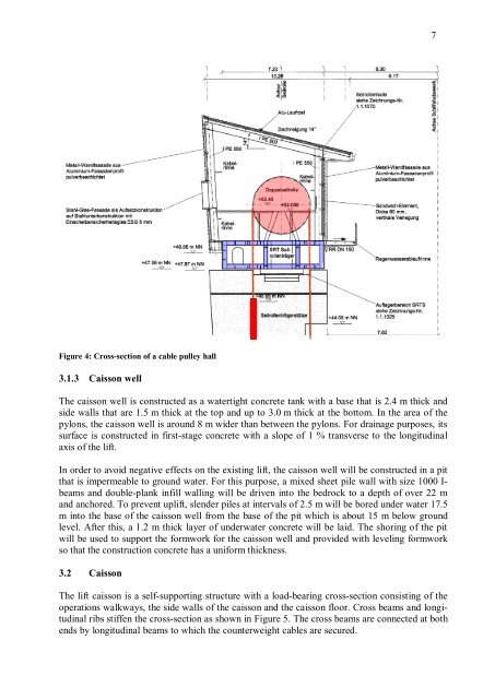
Figure 4: Cross-section of a cable pulley hall<br />
3.1.3 Caisson well<br />
The caisson well is constructed as a w<strong>at</strong>ertight concrete tank with a base th<strong>at</strong> is 2.4 m thick and<br />
side walls th<strong>at</strong> are 1.5 m thick <strong>at</strong> the top and up to 3.0 m thick <strong>at</strong> the bottom. In the area of the<br />
pylons, the caisson well is aro<strong>und</strong> 8 m wider than between the pylons. For drainage purposes, its<br />
surface is constructed in first-stage concrete with a slope of 1 % transverse to the longitudinal<br />
axis of the <strong>lift</strong>.<br />
In order to avoid neg<strong>at</strong>ive effects on the existing <strong>lift</strong>, the caisson well will be constructed in a pit<br />
th<strong>at</strong> is impermeable to gro<strong>und</strong> w<strong>at</strong>er. For this purpose, a mixed sheet pile wall with size 1000 Ibeams<br />
and double-plank infill walling will be driven into the bedrock to a depth of over 22 m<br />
and anchored. To prevent up<strong>lift</strong>, slender piles <strong>at</strong> intervals of 2.5 m will be bored <strong>und</strong>er w<strong>at</strong>er 17.5<br />
m into the base of the caisson well from the base of the pit which is about 15 m below gro<strong>und</strong><br />
level. After this, a 1.2 m thick layer of <strong>und</strong>erw<strong>at</strong>er concrete will be laid. The shoring of the pit<br />
will be used to support the formwork for the caisson well and provided with leveling formwork<br />
so th<strong>at</strong> the construction concrete has a uniform thickness.<br />
3.2 Caisson<br />
The <strong>lift</strong> caisson is a self-supporting structure with a load-bearing cross-section consisting of the<br />
oper<strong>at</strong>ions walkways, the side walls of the caisson and the caisson floor. Cross beams and longitudinal<br />
ribs stiffen the cross-section as shown in Figure 5. The cross beams are connected <strong>at</strong> both<br />
ends by longitudinal beams to which the counterweight cables are secured.<br />
7