New ship lift at Niederfinow - Krebs und Kiefer, Beratende ...
New ship lift at Niederfinow - Krebs und Kiefer, Beratende ...
New ship lift at Niederfinow - Krebs und Kiefer, Beratende ...

You also want an ePaper? Increase the reach of your titles
YUMPU automatically turns print PDFs into web optimized ePapers that Google loves.
3.3 Caisson safety system<br />
The caisson safety system prevents overloading of the pinion and the brakes of the drive by securing<br />
the caisson by means of four rotary locking bars in four internally threaded columns. This<br />
oper<strong>at</strong>ing situ<strong>at</strong>ion constitutes an emergency and can occur if the caisson is emptied or overfilled.<br />
Planned emptying of the caisson also takes place approxim<strong>at</strong>ely once a year for inspection<br />
and repair purposes.<br />
The internally threaded columns are 41.6 m long, with a split internal thread anchored inside the<br />
pylons, and consist of several sections. The rotary locking bars, connected with the caisson via<br />
pendulum supports, have 4 thread pitches, a height of 3 m and an outer diameter of 1.08 m. Each<br />
weighs aro<strong>und</strong> 10 t. At right angles to the caisson, the four axes of the internally threaded columns<br />
are 30 m apart, and lengthwise along the caisson they are 69.85 m apart.<br />
During normal oper<strong>at</strong>ion, the caisson drives rot<strong>at</strong>e the rotary locking bars freely via a coupled<br />
shaft system. Up to the point of settlement on the internally threaded columns, the force on the<br />
pinion corresponds to the external force on the spring housing, taking leverage into account.<br />
Taking into account friction, acceler<strong>at</strong>ing/braking forces and wind forces and a w<strong>at</strong>er level in the<br />
caisson of less than 0.08 m, the force on the spring housing is less than 200 kN.<br />
The pre-loading of the springs is selected so th<strong>at</strong> the pinion does not start to deflect against the<br />
spring until a force of 200 kN is exceeded. When spring deflection in one spring housing starts,<br />
the 4 caisson drives are stopped. The force on the pinion then increases in accordance with the<br />
spring characteristics. When the force on the pinion reaches 990 kN, the rotary locking bar settles<br />
in the internally threaded column and absorbs the differential loads until the maximum imbalance<br />
load has been applied and a force of 1090 kN therefore acts on the pinion. The force<br />
acting on the pinion is continuously measured, both while the caisson is st<strong>at</strong>ionary and while it is<br />
moving. In the event th<strong>at</strong> the maximum oper<strong>at</strong>ing force on the pinion is exceeded, the drive is<br />
switched off and the pinion deflects against the spring.<br />
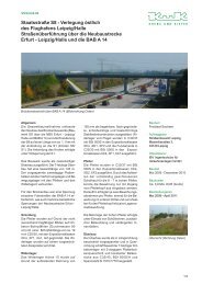
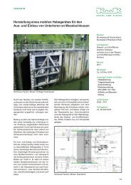
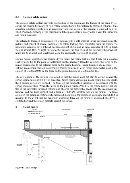
4. Canal bridge<br />
Figure 6: Canal bridge<br />
9