New ship lift at Niederfinow - Krebs und Kiefer, Beratende ...
New ship lift at Niederfinow - Krebs und Kiefer, Beratende ...
New ship lift at Niederfinow - Krebs und Kiefer, Beratende ...

Create successful ePaper yourself
Turn your PDF publications into a flip-book with our unique Google optimized e-Paper software.
The cross beams, which are reinforced in the area of the caisson quarters, transfer the imbalance<br />
loads into the load-bearing structure via the caisson safety system. The drives th<strong>at</strong> run through<br />
the pylons are loc<strong>at</strong>ed in this area <strong>at</strong> the sides of the caisson. Machine housings protect the<br />
drives.<br />
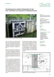
The specific<strong>at</strong>ions on the use of the <strong>lift</strong> result in an overall caisson length of 125.5 m, a width of<br />
18.3 m in the area of the counterweights and of 27.9 m in the area of the drive housings; the construction<br />
height in the area of the counterweights is 6.3 m. In the area of the caisson safety system,<br />
the cross beams are 2.5 m high, resulting in a construction height in th<strong>at</strong> area of 7.5 m. The<br />
oper<strong>at</strong>ions walkways along the sides <strong>at</strong> the top of the caisson are 2.0 m wide; those in the area of<br />
the <strong>ship</strong> arrester equipment are 0.6 m wide and those <strong>at</strong> the height of the caisson base are 1.1 m<br />
wide. During motion, the caisson is guided in transverse and longitudinal directions in such a<br />
way th<strong>at</strong> it moves <strong>at</strong> equal distances between transverse guides.<br />
While moving into or out of the caisson, <strong>ship</strong>s cause fluctu<strong>at</strong>ions in the w<strong>at</strong>er level. In order to<br />
reduce the resulting loads on the drives, the caisson is secured by a caisson locking mechanism<br />
when it is <strong>at</strong> the docking points. This locking system is designed for a caisson imbalance corresponding<br />
to a w<strong>at</strong>er level fluctu<strong>at</strong>ion of 25 cm. A l<strong>at</strong>ch design is envisaged which is secured to<br />
the caisson and locks by means of a travelling counterpart (locking bar). To protect the locking<br />
mechanism from damage in the event of gre<strong>at</strong>er imbalance, it yields when overloaded so th<strong>at</strong> the<br />
caisson begins to move. The rotary locking bars of the caisson safety system then engage with<br />
the internally threaded columns.<br />
Swivel-radial g<strong>at</strong>es close off the caisson <strong>at</strong> both ends. When open, they are rot<strong>at</strong>ed into niches in<br />
the floor, and they can be rot<strong>at</strong>ed upwards out of the w<strong>at</strong>er for inspection purposes. The g<strong>at</strong>es are<br />
moved by two electric jacks, each with 650 kN drive force. A cable-arrester facility protects the<br />
g<strong>at</strong>es against <strong>ship</strong> impact.<br />
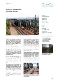
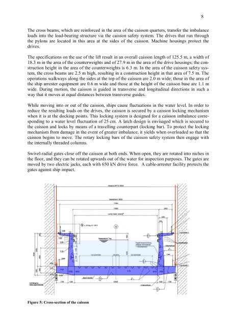
Figure 5: Cross-section of the caisson<br />
8