Expand Hydrocracker Operating Window Through Process ...
Expand Hydrocracker Operating Window Through Process ...
Expand Hydrocracker Operating Window Through Process ...
- No tags were found...

You also want an ePaper? Increase the reach of your titles
YUMPU automatically turns print PDFs into web optimized ePapers that Google loves.
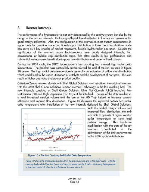
3. Reactor InternalsThe performance of a hydrocracker is not only determined by the catalyst system but also by thedesign of the reactor internals. Uniform gas/liquid flow distribution in the reactor is essential forgood catalyst utilization. Also, the configuration of the internals to meet quench requirements inupper beds for gasoline mode and liquid/vapor distribution in lower beds for distillate modecan serve as a key enabler of market responsive, flexible hydrocracker operation. Despite thesignificance of the internals, many hydrocrackers have poorly designed internals, i.e.,conventional or bubble cap distribution trays, that often results in lost performance andsubstantial lost economic benefit due to poor flow distribution and under-utilized catalyst.During the 2004 cycle, the DPRC hydrocracker‗s last cracking bed showed high radial deltatemperature. The problem was particularly severe toward the end of the run, as seen in Figure10 below. The high radial delta temperature is generally an indication of a flow mal-distribution,which could lead to the under-utilization of catalysts and the development of hot spots. This canresult in higher gas make and poorer product quality.Criterion/Zeolyst worked closely with Shell Global Solutions and retrofitted the original internalswith the latest Shell Global Solutions Reactor Internals Technology in the last cracking bed. Thenew internals consisted of Shell Global Solutions Ultra Flat Quench (UFQ) including Pre-Distribution (PD) and High Dispersion (HD) trays at the interbed. The use of the UFQ resulted ina total increased catalyst volume and the use of the HD Tray helped to increase catalystutilization and improve flow distribution. Figure 10 illustrates the improved bottom bed radialdelta temperature after installation of the new internals designed by Shell Global Solutions.With the added catalyst volume andimproved flow distribution, the unitwas able to operate at higher reactoroutlet temperature to save feedpreheat energy. This hardwaremodification with the state of the artinternals contributed to theoptimization of the unit performancein the 2007 cycle stated above.Figure 10 – The Last Cracking Bed Radial Delta TemperatureFigure 10 shows the cracking bed radial dT in the previous cycle and in the 2007 cycle—with thecracking bed radial dT on the Y axis and days on stream on the X axis—illustrating the improvedbottom bed radial dT after the installation of the new internals.AM-10-145Page 13