Remote Control Car Starter Installation Manual for ... - Ready Remote
Remote Control Car Starter Installation Manual for ... - Ready Remote
Remote Control Car Starter Installation Manual for ... - Ready Remote
- No tags were found...

Create successful ePaper yourself
Turn your PDF publications into a flip-book with our unique Google optimized e-Paper software.
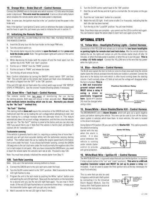
10. Orange Wire – Brake Shut-off – <strong>Control</strong> HarnessConnect the ORANGE wire to the brake wire which receives +12 Volts when the brakepedal is depressed. This wire must be connected. It arms a critical safety featurewhich disables the remote starter when the brake pedal is depressed.Note: In some cars, the ignition must be in the “on” position to test the power in thebrake wire.Note: If the Ignition 1 and Ignition 2 wires come on whenever the brake is depressedand the hood is open this just means you need to initialize the unit in section 11.11. Initializing the <strong>Remote</strong> <strong>Starter</strong>BEFORE THE UNIT WILL DO ANYTHING FOR THE FIRST TIME, YOU MUST INITIALIZETHE REMOTE STARTERA. Insert the 30 amp fuse into the fuse holder on the large PINK wire.B. Turn the control switch on.C. The remote starter requires the installer to open the hood and then press andhold the brake pedal. Note: The ignition/dash lights will come on if the unit isnot initialized.D. While depressing the brake (with the engine off and the hood open) turn theignition key to the “RUN” (not “start”) position.E. Put the car in “DRIVE” from the “PARK” position.F. Put the car back in “PARK” and release the brake.G. Turn the key off and remove the key.Note: Confirm initialization by turning the ON/OFF control switch “OFF” and then“ON”. The red LED light on the remote start module will flash once immediately asthe switch is flipped from the “OFF” to the “ON” position.If the red LED light did not flash when the control switch was turned “ON” REPEATSTEPS A THROUGH G. See the colored Trouble Shooting Sheets if necessary.12A. Green Wire – Tach Input – <strong>Control</strong> HarnessThe remote starter has two ways of monitoring the car duringthe starting process. Both ways will ensure a clean, accurate start. Read aboutboth methods be<strong>for</strong>e deciding which one to use. Normally you shouldtry the “No Tach ” method first.“No Tach ” StartingThis starting method does not require the connection of the GREEN tach wire. Thismethod will start the car by reading the car’s voltage be<strong>for</strong>e attempting to start, andthen looking <strong>for</strong> a voltage increase when the alternator kicks in. This featureautomatically takes into account voltage, temperature, and the time since the vehiclewas last run. The “No-Tach ” starting is preset at the factory and you can skip step12B if you would like to use it. Note that if the vehicle is hard to start, set Option #3(section 24) <strong>for</strong> “extended crank.”Tachometer sensingIf the vehicle is generally hard to start (i.e. requiring a cranking time of more than 1second) you will get more accurate starting with the tachometer sensing startingmethod. This method starts the car by reading the engine speed (tach) in<strong>for</strong>mationfrom a wire under the hood. If you choose tachometer sensing, connect the GREEN(18 awg) wire to the car’s tach wire under the hood (normally the negative side of thecoil or tach output of coil pack). After you have connected the GREEN wire, you needto teach the remote starter the vehicle’s tach rate at idle. Proceed to step 12B.Note: You must have already initialized the remote starter from Step 11.12B. Tach Rate LearningNote: Only use if the tachometer sensing method is chosen.A. Connect the GREEN wire to the car’s tach wire under the hood.B. Turn the On/Off control switch to the “OFF” position. Wait 5 seconds <strong>for</strong> the redLED light flashes to stop.C. Program the unit to the tach mode by pushing the White “option” button onceand watching the red LED light flash. Now push the start button on the transmitter<strong>for</strong> a second until you see the red LED light flash again. You are now in TACHmode. (If the red LED light flashed twice or sometimes three times – simply pushthe transmitter button again until you get only one flash).D. Wait 5 seconds <strong>for</strong> the red LED light to flash 3 times.E. Turn the On/Off control switch back to the “ON” positionF. Start the car with the key and let it get to a normal idle. Do not press on the gaspedal.G. Push the red “code learn” button <strong>for</strong> a second.H. Watch the red LED light. It will come on after 3 or 4 seconds, indicating that thetach idle rate has been learned.I. Turn the key to the “Lock/Off” position. You are now finished.Note: Once these steps are complete – you cannot use the LED to confirm tach again.You can however repeat the above steps to learn tach over again at any time.OPTIONAL STEPS13. Yellow Wire – Headlights/Parking Lights – <strong>Control</strong> HarnessConnection of the YELLOW wire allows you to activate the low beam headlightsor parking lights <strong>for</strong> remote start and lock status. After the remote starter hasstarted the car, the lights will remain on until the remote starter shuts off after 10minutes, or when the brake pedal is pushed, or when the car is put into gear. This isa relay +12 Volts output. Connect the YELLOW wire to the wire that has powerwhen the lights are on.14. Blue – Horn/Siren – <strong>Control</strong> HarnessThe BLUE wire signals the horn to honk (or siren to chirp) once each time the remotestarter starts the vehicle and each time the locks are locked or unlocked. Connect theblue wire to the factory horn wire which is often found running down the steeringcolumn. It will normally show +12 Volts at rest and the voltage will disappear whenthe horn is honked. This isa 400 mA transistorPositive Horn/Siren Relayground output whichMUST drive a relay ifusing a siren orpositively triggeredhorn. Option #11 (section24) must be changed whenusing a siren.15. Brown/White – Alarm Disable/<strong>Starter</strong> Kill – <strong>Control</strong> HarnessThe BROWN/WHITE wire is Alarm Disable, which will give out a quick negativepulse just be<strong>for</strong>e starting the vehicle. This wire can be used to turn off the factoryalarm system in vehicles which have them. In most vehicles, this wire is locatedin the driver’s kick panel.Using Option #19 (section 24) you can set this to <strong>Starter</strong> Kill. This option preventsthe vehicle from being<strong>Starter</strong> Kill Relaystarted with the keywhen the alarm is<strong>Starter</strong> Wire<strong>Starter</strong> Wirearmed. It is alsoFrom KeyCutTo <strong>Starter</strong>SwitchMotoractive whenever the87vehicle is running<strong>Remote</strong> <strong>Starter</strong>Tap into BlueBrown / WhiteIGN1 Wire from87AWire 86 30 85<strong>Remote</strong> <strong>Starter</strong>under remote startercontrol to provide Yellow Start WireFrom <strong>Remote</strong> <strong>Starter</strong>anti-grind protection.16. White/Black Wire – Ignition #3 – <strong>Control</strong> HarnessThe WHITE/BLACK wire, is a ground output that acts just like the Ignition 1 or Ignition2 relay outputs (active in the “run” and “crank” positions). This wire is a 400 mAnegative transistor output and MUST be set up to power a relay (notincluded). It can be used to power the third ignition wire at the key (necessary <strong>for</strong>most Ford vehicles).This is a wire that can also be usedto bypass a vehicle anti-theft systemby connecting it to the UniversalAlarm Bypass Module. See theFactory Anti-Theft System section atthe end of the instructions.Ignition 3White/Black Wire 87From87A<strong>Remote</strong> <strong>Starter</strong> 85 30To LARGE 12 VoltConstant Wire(Found in IgnitionSwitch WireHarness)To AdditionalIgnition Wire(in vehicle)3 v3.1 242886