OPTISOUND3030-3050C - Forbes Marshall
OPTISOUND3030-3050C - Forbes Marshall
OPTISOUND3030-3050C - Forbes Marshall

Create successful ePaper yourself
Turn your PDF publications into a flip-book with our unique Google optimized e-Paper software.
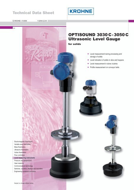
Description of the measuring principle1 Description of the measuring principleMeasuring principleShort ultrasonic pulses in the range of 18 kHzto35 kHz are emitted by the transducerto the product surface, reflected there and received by the transducer. The pulsestravel at the speed of sound - the elapsed time from emission to reception of thesignals depends on the level in the vessel.The latest microcomputer technology and the proven processing software select thelevel echo from among any number of false echoes and calculate the exact distance tothe product surface. An integrated temperature sensor detects the temperature in thevessel and compensates the influence of temperature on the signal running time.By simply entering the vessel dimensions, a level-proportional signal is generatedfrom the distance. It is not necessary to fill the vessel for adjustment.Wide application rangeOPTISOUND 3030 C, 3040 C and 3050 C ultrasonic sensors are especially suitablefor level measurement of solids, but are also good for liquids. The instruments differ inthe measuring range, the transducer version and the process fitting. Through different,adapted emitting frequencies and efficient transducers, levels in a measuringrange of 15 … 45 m (49.2 … 147.6 ft) can be measured. Resistant materials for thetransducers and process fittings also allow applications in corrosive products (dependingon the model).A version suitable for each applicationAdaptable sensors are a must for the wide variety of product characteristics andinstallation conditions. OPTISOUND ultrasonic sensors meet this requirement withversions suitable for all applications.A practical mounting strap (option) enables flexible orientation of OPTISOUND 3030C.Four different versions of OPTISOUND 3040 C and 3050 C enable installation invirtually all vessels and optimum orientation to the product cone:l Version A compact in flange versionl Version B compact with swivelling holderl Version C separate with swivelling holderl Version D separate with thread fitting.Unaffected by product propertiesFluctuations in product composition or even complete product changes do not influencethe measuring result. A fresh adjustment is not necessary.Service and maintenance friendlyThanks to the non-contact measuring principle, OPTISOUND sensors are particularlyeasy to service and maintain.30601-EN-050816Ultrasonic – Level measurement in solids 3
Description of the measuring principle1.1 Application examplesConveyor belt with sugar beetsFig. 1: Profile measurement on a conveyor belt with OPTISOUND 3030CThe sugar beets used for sugar production are poured from trucks onto conveyor beltson which they are transported for further processing. OPTISOUND sensors are aneconomic solution for profile monitoring. Ultrasonic waves are reflected by the medium,the integrated electronics detects the charging height of the conveyor belt. Bymeans of the mounting strap, OPTISOUND 3030 C can be optimally oriented to themedium. Thanks to its high emitting power, fog, wind and moisture do not affectmeasurement reliability.30601-EN-0508164 Ultrasonic – Level measurement in solids
Description of the measuring principlePlastic granulesFig. 2: Level measurement in a plastic granules silo with OPTISOUND3040 CPlastic granules are often stored in high, narrow silos that are filled pneumatically.OPTISOUND ultrasonic sensors are particularly suitable for level measurement ofplastic granules. They are equipped with powerful transducers and optimised signalprocessing. A swivelling holder on the mounting flange ensures optimum orientationto the product, also when material cones form.30601-EN-050816Ultrasonic – Level measurement in solids 5
Type overview2 Type overviewOPTISOUND 3030 COPTISOUND 3040 CPreferred application: liquids and solids SolidsMeasuring range:liquids: 0.6 … 15 m (2 … 49.2 ft) liquids: 1 … 25 m (3.3 … 82 ft)solids: 0.6 … 7 m (2 … 23 ft)solids: 1 … 15 m (3.3 … 49.2 ft)Process fitting:compression flange DN 100 or mountingstrapflange DN 200, with swivelling holder fromDN 50Process temperature: -40 … +80°C (-40 … +176°F) -40 … +80°C (-40 … +176°F)Process pressure:-20 … 100 kPa(-0.2 … 1.0 bar/-2.9 … 14.5 psi)-20 … 150 kPa(-0.2 … 1.5 bar/-2.9 … 21.8 psi)Signal output two-wire/four-wire 4 … 20 mA/HART four-wire 4 … 20 mA/HARTOPTISOUND 3050 CPreferred application:Measuring range:Process fitting:Process temperature:Process pressure:Signal outputSolidsliquids: 0.8 … 45 m (2.6 … 147.6 ft)solids: 0.8 … 25 m (2.6 … 82 ft)flange DN 250, with swivelling holderfrom DN 50-40 … +80°C (-40 … +176°F)-20 … 150 kPa(-0.2 … 1.5 bar/-2.9 … 21.8 psi)four-wire 4 … 20 mA/HART30601-EN-0508166 Ultrasonic – Level measurement in solids
Type overviewIndicating andadjustment moduleHousingPlastic Stainless steel Aluminium Aluminium(double chamber)Electronics4 … 20 mA/HART four-wireSensorsTransducer15 mTransducer25 mTransducer45 mApprovalsDust explosionprotection30601-EN-050816Ultrasonic – Level measurement in solids 7
Mounting information3 Mounting informationMeasuring rangeThe reference plane for the measurement depends on the version. For the OPTI-SOUND 3040 C and 3050 C in flange version (version A) the lower edge of the flangeis the reference plane. For the versions with swivelling holder (versions B and C), withthreaded fitting (version D) as well as for OPTISOUND 3030 C, the lower edge of thetransducer is the reference plane. All statements concerning the measuring range aswell as the internal signal relate to this plane.With all instruments, amin. distance from the lower edge of the flange - the so-calleddead zone, in which measurement is not possible - must be maintained. The exactvalue of the dead zone, depending on the instrument version, is stated in the Technicaldata.12Fig. 3: Min. distance to the max. level on the example of an OPTI-SOUND 3030 C1 Dead zone2 Reference plane for the measurementNote:If the product reaches the transducer, buildup can form on it over a period of time andlater cause measurement errors.1 2 3100%40%Fig. 4: OPTISOUND 3040 C and 3050 version A – Measuring range(operating range) and max. measuring distance1 full (dead zone)2 empty (max. measuring distance)3 Measuring range4 Reference plane30601-EN-0508168 Ultrasonic – Level measurement in solids
Mounting information1 2 3100%40%Fig. 5: OPTISOUND 3030 C … 3050 C version B, C, D – Measuringrange (operating range) and max. measuring distance1 full (dead zone)2 empty (max. measuring distance)3 Measuring range4 Reference planePressure/VacuumInstallation positionGauge pressure in the vessel does not influence OPTISOUND. Low pressure orvacuum, however damp the ultrasonic pulses. This influences the measuring result,particularly if the level is very low. With pressures under -0,2 bar (-20 kPa) use adifferent measuring principle, e.g. radar or guided radar (TDR).The mounting position of OPTISOUND 3030 C must be at least 200 mm (OPTI-SOUND 3040 C and 3050 C - at least 500 mm) from the vessel wall. If the sensor isinstalled in the center of dished or spherical vessel tops, multiple echoes can result.These can be faded out, however, through an appropriate adjustment.If you cannot keep this distance, a false echo storage should be carried out duringsetup. This applies particularly if buildup on the vessel wall is expected. In this case,we recommend repeating the false echo storage later on with existing buildup.30601-EN-050816Ultrasonic – Level measurement in solids 9
Mounting information1 2> 200 mmFig. 6: Mounting of OPTISOUND 3030 C on round vessel tops1 Reference plane2 Vessel center or symmetry axis1> 500 mmFig. 7: Mounting of OPTISOUND 3040 C and 3050 C on round vesseltops1 Reference planeIn vessels with conical bottom it can be advantageous to mount the sensor in thecenter of the vessel, as measurement is then possible down to the lowest point of thevessel bottom.30601-EN-05081610 Ultrasonic – Level measurement in solids
Mounting informationFig. 8: OPTISOUND 3030 C on a vessel with conical bottom – MediumliquidFig. 9: OPTISOUND 3040 C on a vessel with conical bottom – MediumsolidSocketSensor orientationThe transducer should be mounted preferably without socket, flush with the vesseltop.Ifthereflective properties of the medium are good, you can mount OPTISOUND on asocket piece higher than the transducer length. The socket end should be smooth andburr-free, if possible, also rounded. A false echo storage is recommended.With liquids, align the sensor as close to vertical as possible to achieve optimummeasuring results.30601-EN-050816Fig. 10: Orientation in liquidsUltrasonic – Level measurement in solids 11
Mounting informationThe version with swivelling holder is recommended for optimum orientation to solids.Vessel installationsThe ultrasonic sensor should be installed at a location where no installations cross theultrasonic beam.Vessel installations such as, for example, ladders, limit switches, heating spirals,struts, etc. can cause false echoes superimposed on the wanted echo. Make surewhen planning your measuring location that the ultrasonic signals have "free access"to the measured product.If there are existing vessel installations, a false echo storage should be carried outduring setup.If large vessel installations such as struts or supports cause false echoes, these canbe attenuated through supplementary measures. Small, inclined sheet metal or plasticbaffles above the installations scatter the ultrasonic signals and avoid direct falseechoes.Fig. 11: Cover smooth profiles with deflectorsMaterial heapsLarge material heaps are detected with several sensors, which can be mounted on e.g. traverse cranes. For this type of application, it is best to direct the sensor perpendicularlyto the solid surface.Fig. 12: Transducers on traverse craneInflowing materialThe instruments must not be mounted in or above the filling stream. Make sure that theproduct surface and not the inflowing material is detected.30601-EN-05081612 Ultrasonic – Level measurement in solids
Mounting informationFig. 13: Inflowing liquidFoamAir flowHeat fluctuationsThrough the action of filling, stirring and other processes in the vessel, dense foamswhich considerably damp the emitted signals may form on the product surface.If foams are causing measurement errors, the sensor should be used in a standpipeor, alternatively, the more suitable sensors with guided radar (TDR) should be used.Guided radar is not influenced by foam generation and is particularly suitable for suchapplications.If there are strong air currents in the vessel, e.g. due to strong winds in outdoorinstallations, or because of air turbulence, you should mount OPTISOUND in a standpipeor use a different measuring principle, e.g. radar or guided radar (TDR).Strong heat fluctuations, e.g. caused by the sun, can cause measurement errors. Inthis case, you should use a sun shield.Fig. 14: Protection against the sun30601-EN-050816Ultrasonic – Level measurement in solids 13
Electrical connection4 Electrical connection4.1 General requirementsThe power supply range can differ depending on the instrument version. The exactrange is stated in the Technical data.Take note of country-specific installation standards (e.g. the VDE regulations in Germany)as well as prevailing safety regulations and accident prevention rules.In hazardous areas you should take note of the appropriate regulations, conformityand type approval certificates of the sensors and power supply units.4.2 Supply voltage4 … 20 mA/HART two-wire4 … 20 mA/HART four-wirePower supply and current signal are carried over the same two-wire connection cable.The requirements on the power supply are stated in the Technical data of this ProductInformation manual.Power supply and current output are carried on two separate connection cables.The standard version can be operated with an earth-connected current output, theExd version must be operated with a floating output.The instrument is designed in protection class I. To maintain this protection class, it isabsolutely necessary that the ground conductor be connected to the internal groundconductor terminal.4.3 Connection cableThe sensors are connected with standard cable without screen. An outer cable diameterof 5 … 9 mm ensures the seal effect of the cable entry.If strong electromagnetic interference is expected, screened cable should be used forthe signal lines.In Ex applications, the corresponding installation regulations must be noted for theconnection cable.4.4 Connection of the cable screen and groundingIf screened cable is required, the cable screen must be connected on both ends toground potential. If potential equalisation currents are expected, the connection onthe evaluation side must be made via a ceramic capacitor (e.g. 1 nF, 1500 V).30601-EN-05081614 Ultrasonic – Level measurement in solids
Electrical connection4.5 Wiring plans OPTISOUND 3030 CSingle chamber housingDisplayI2C1 2 5 6 7 81Fig. 15: Connection HART two-wire, Profibus PA, Foundation Fieldbus1 Power supply and signal outputDouble chamber housing– two-wireI2C1 21Fig. 16: Connection HART two-wire, Profibus PA, Foundation Fieldbus1 Power supply and signal outputDouble chamber housing– 4 … 20 mA/HARTfour-wireL1 N4...20mA ISGND1 2 3 41/ L/ N4 ... 20 mA 2PEFig. 17: Connection 4 … 20 mA/HART four-wire1 Supply voltage2 Signal output30601-EN-050816Ultrasonic – Level measurement in solids 15
Electrical connection4.6 Wiring plans OPTISOUND 3040 C and 3050 CDouble chamber housing– 4 … 20 mA/HARTfour-wireL1 N4...20mA ISGND1 2 3 41/ L/ N4 ... 20 mA 2PEFig. 18: Connection 4 … 20 mA/HART four-wire1 Supply voltage2 Signal output30601-EN-05081616 Ultrasonic – Level measurement in solids
Adjustment5 Adjustment5.1 Adjustment, generalOPTISOUND can be adjusted with the following adjustment media:l the indicating and adjustment modulel a HART handheld (4 … 20 mA/HART)The entered parameters are generally saved in OPTISOUND, optionally also in theindicating/adjustment module.5.2 Compatibility acc. to NAMUR NE 53OPTISOUND meet NAMUR recommendation NE 53.The parameter adjustment of the basic sensor functions is independent of the softwareversion. The range of available functions depends on the respective softwareversion of the individual components.30601-EN-050816Ultrasonic – Level measurement in solids 17
Adjustment5.3 Adjustment with the indicating/adjustment moduleSetup and indicationThe indication and adjustment module can be plugged into OPTISOUND sensors. Itcan be placed in four different positions on the instrument (each displaced by 90°).Indication and adjustment are made via four keys and a clear, graphic-capable dotmatrix indication. The adjustment menu with language selection is clearly structuredand enables easy setup. After setup, the indicating/adjustment module serves asindicating instrument: through the screwed cover with glass insert, measured valuescan be read directly in the requested unit and presentation.Adjustment121.13Fig. 19: Indicating and adjustment elements1 LC display2 Indication of the menu item number3 Adjustment keysKey functionsllll[OK] key:- move to the menu overview- confirm selected menu- edit parameter- save value[–>] key to select:- menu change- list entry- editing position[+] key:- modify value of a parameter[ESC] key:- interrupt input- jump to the next higher menu30601-EN-05081618 Ultrasonic – Level measurement in solids
Technical data6 Technical dataOPTISOUND 3030 COPTISOUND 3040 C and 3050 CGeneral dataMaterials, wetted parts- Mounting strap 1.4301- Process fitting UP- transducer diaphragm 316Ti (1.4571)- Seal transducer/process fitting EPDMMaterials, non-wetted parts- Compression flange PPH, 316L (1.4435)- Housing plastic PBT (Polyester), Alu-die castingpowder-coated, 1.4435- Seal ring between housing and housingcoverNBR (stainless steel housing), silicone(Alu/plastic housing)- Inspection window in housing cover Polycarbonate (UL746-C listed)for indicating/adjustment module- Ground terminal 316Ti/316L (1.4571/1.4435)Weight 1)2.7 … 5.7 kg (6 … 12.6 lbs)Materials, wetted parts- Flange PP or Alu- swivelling holder, threaded fitting galvanized steel- Transducer OPTISOUND 3040 C PA (1.4301 with StEx)- Transducer OPTISOUND 3040 C and UP3050 C- Transducer diaphragm OPTISOUND 316Ti (1.4571)3040 C- Transducer diaphragm OPTISOUND Alu/PE foam rubber coating3050 CMaterials, non-wetted parts- Housing Alu die-casting powder-coated- Seal ring between housing and housingsiliconecover- Inspection window in housing cover Polycarbonate (UL746-C listed)for indicating/adjustment module- Ground terminal 316Ti/316L (1.4571/1.4435)- Transducer cable OPTISOUND 3040 PUR (1.1082)C and 3050 CWeight 2) OPTISOUND 3040 C- Version A 5.6 … 10.7 kg (12.3 … 23.6 lbs)- Version B 6.9 … 9.7 kg (15.2 … 21.4 lbs)- Version C 7.5 … 10.5 kg (16.5 … 23.1 lbs)- Version D 4.7 … 6.9 kg (10.4 … 15.2 lbs)Weight 3) OPTISOUND 3050 C- Version A 8.0 … 13.3 kg (17.6 … 29.3 lbs)- Version B 8.7 … 10.3 kg (19.2 … 22.7 lbs)- Version C 9.2 … 11.1 kg (20.3 … 24.5 lbs)- Version D 6.5 … 7.5 kg (14.3 … 16.5 lbs)30601-EN-0508161)2)3)Depending on the process fitting and housing.Depending on process fitting.Depending on process fitting.Ultrasonic – Level measurement in solids 19
Technical dataOutput variableOutput signal4 … 20 mA/HARTResolution 1.6 µAFault signalcurrent output unchanged; 20.5 mA;22 mA;
Technical dataUltrasonic frequency/Beam angle- OPTISOUND 3030 C 35 kHz/5.5°- OPTISOUND 3040 C 30 kHz/4°- OPTISOUND 3050 C 18 kHz/5°IntervalAdjustment time 5)Accuracy>2 s (dependent on the parameter adjustment)>3 s (dependent on the parameter adjustment)better than 0.2 % or ±6 mm (see respectivediagram)OPTISOUND 3030 C30 mm20 mm10 mm6 mm-6 mm3 m4 m 6 m 8 m 10 m 12 m15 m-10 mm-20 mm-30 mmFig. 20: Accuracy diagram OPTISOUND 3030 COPTISOUND 3040 C50 mm25 mm6 mm-6 mm3 m5 m 10 m 15 m 20 m25 m-25 mm-50 mmFig. 21: Accuracy diagram OPTISOUND 3040 C – Version A30601-EN-0508165)Time to output the correct level (with max. 10 % deviation) after a sudden level change.Ultrasonic – Level measurement in solids 21
Technical data50 mm25 mm6 mm-6 mm3 m5 m 10 m 15 m 20 m25 m-25 mm-50 mmFig. 22: Accuracy diagram OPTISOUND 3040 C – Versions B, C, DOPTISOUND 3050 C90 mm60 mm30 mm6 mm-6 mm3 m15 m30 m45 m-30 mm-60 mm-90 mmFig. 23: Accuracy diagram OPTISOUND 3050 C – Version A30601-EN-05081622 Ultrasonic – Level measurement in solids
Technical data90 mm60 mm30 mm6 mm-6 mm3 m15 m30 m45 m-30 mm-60 mm-90 mmFig. 24: Accuracy diagram OPTISOUND 3050 C – Versions B, C, DAmbient conditionsAmbient, storage and transport temperature- without indicating and adjustment -40 … +80°C (-40 … +176°F)module- the indicating and adjustment module -20 … +70°C (-4 … +158°F)Process conditionsVessel pressure- Input variable OPTISOUND 3030 C -20 … 100 kPa (-with compression flange0.2 … 1 bar/-2.9 … 14.5 psi)- OPTISOUND 3030 C with mounting 0 kPa (0 bar/0 psi), because no sealingstrappossibility- OPTISOUND 3040 C and 3050 C -20 … 50 kPa (-0.2 … 0.5 bar/-2.9 … 7.3 psi)- OPTISOUND 3040 C and 3050 C – 0 kPa (0 bar/0 psi)Version A with PP flangeProcess temperature (transducer temperature)-40 … +80°C (-40 … +176°F)Vibration resistancemechanical vibrations with 4 g and5 … 100 Hz 6)30601-EN-0508166)Tested acc. to the regulations of German Lloyd, GL directive 2Ultrasonic – Level measurement in solids 23
Technical dataElectromechanical dataCable entry- Single chamber housing l 1x cable entry M20x1.5 (cable-ø5 … 9 mm), 1x blind stopperM20x1.5or:l1x closing cap ½ NPT, 1x blindstopper ½ NPT- Double chamber housing l 1x cable entry M20x1.5 (cable-ø5 … 9 mm), 1x blind stopperM20x1.5or:l1x closing cap ½ NPT, 1x blindstopper ½ NPTSpring-loaded terminalsfor wire cross sections up to 2.5 mm²30601-EN-05081624 Ultrasonic – Level measurement in solids
Technical dataIndicating and adjustment modulePower supply and data transmission through sensor via gold-plated slidingcontacts (I²C bus)IndicationLC display in full dot matrixAdjustment elements4 keysProtection- unassembled IP 20- mounted into the sensor without cover IP 40Materials- Housing ABS- Inspection window Polyester foilSupply voltagePower supply – two-wire instrument- non-Ex instrument 14 ... 36 VDC- EEx ia instrument 14 ... 30 VDCPermissible residual ripple- < 100 Hz Uss < 1 V- 100 Hz ... 10 kHz Uss < 10 mVLoadsee diagramΩ1000750500250114 16 18 20 22 24 26 28 30 32 34 36234VFig. 25: Voltage diagram1 HART load2 Voltage limit EEx ia instrument3 Voltage limit non-Ex instrument4 Supply voltageSupply voltage – four-wire instrumentPower consumption – four-wire instrument20 ... 72 VDC, 20 ... 253 VAC, 50/60 Hzmax. 4 VA; max. 2.1 W30601-EN-050816Ultrasonic – Level measurement in solids 25
Technical dataElectrical protective measuresProtection- Housing OPTISOUND 3030 C IP66/IP 68 (0.2 bar) 7)- Housing OPTISOUND 3030 C - 3050 IP 66/IP 67C- Transducer IP 68Overvoltage categoryIIIProtection class- two-wire, Profibus PA, Foundation IIFieldbus- four-wire IApprovals OPTISOUND 3040 C and 3050 C 8)9)ATEXCE conformityATEX II 1/2D IP66 TEMC (89/336/EWG)Emission EN 61326: 1997 (class A),susceptibility EN 61326: 1997/A1: 1998LVD (73/23/EWG) EN 61010-1: 20017)8)9)Requirement to maintain the housing protection is the suitable cable.Deviating data with Ex applications: see separate safety instructions.Depending on order specification.30601-EN-05081626 Ultrasonic – Level measurement in solids
Dimensions7 DimensionsHousing~ 69mm(2 23/ 32") ø 77mm(3 1/ 32")~ 69mm(2 23/ 32")ø 77mm(3 1/ 32")~ 87mm (3 27/ 64")ø 84mm(3 5/ 16")~ 116mm(4 9/ 16")ø 84mm(3 5/ 16")M20x1,5/½ NPT112mm(4 13/32")M20x1,5/½ NPT117mm(4 39/64")120mm (4 23/32")M20x1,5/½ NPTM20x1,5114mm(4 31/64")M20x1,5/1 2 ½ NPT 3 4Fig. 26: Housing versions (with integrated indicating/adjustment module the housing height or width isincreased by 9 mm/0.35 in)1 Plastic housing2 Stainless steel housing3 Aluminium double chamber housing4 Aluminium housingOPTISOUND 3030 C130mm (5 1/ 8")1195mm (7 43/64")118mm (4 41/64")M8x122 DN100/ANSI4"3 4118mm (4 41/ 64")ø 148mm (5 53/ 64")ø 158mm (6 7/ 32")Fig. 27: OPTISOUND 3030 C1 Mounting strap2 Compression flange3 Dead zone: 0.6 m (2 ft)4 Meas. range: in liquids up to 15 m (49.2 ft), in solids up to 7 m (23 ft)30601-EN-050816Ultrasonic – Level measurement in solids 27
DimensionsOPTISOUND 3040 C130mm (51/1 8")2max. 15°(19/ 32")110mm (4 21/64")240mm (9 29/64")DN 50 PN16/40DN 80 PN16/40DN 200 PN16DN 250 PN162" 150lb3" 150lb8" 150lb10" 150lbø189mm (7 7/ 16")kDD b165mm 20mm200mm 24mm340mm 24mm405mm 26mmD b6" 3/ 4 "7 1/ 2 " 15/ 16 "13 1/ 2 " 1 1/ 8 "16" 1 3/ 16 "bk125mm160mm295mm355mmk4 3/ 4 "6"11 3/ 4 "14 1/ 4 "d4x ø18mm8x ø18mm12x ø22mm12x ø26mmd3 44x ø3/ 4 "4x ø3/ 4 "8x ø7/ 8 "12x ø 1">ø200mm(7 7/ 8")Dk3 4250mm (9 7/8") 440mm (17 21/64")Fig. 28: OPTISOUND 3040 C1 Version A2 Version B3 Dead zone: 1 m (3.3 ft)4 Measuring range: with liquids up to 25 m (82 ft), with solids up to 15 m (49.2 ft)30601-EN-05081628 Ultrasonic – Level measurement in solids
DimensionsOPTISOUND 3040 C150mm (5 29/1 32")2220mm (8 21/32")>ø200mm(7 7/ 8")250mm (9 7/8") 312mm (12 9/32")G1A18mm(45/64")3 4143mm (5 5/8")149mm (5 55/64")DN 50 PN16/40DN 80 PN16/40DN 200 PN16DN 250 PN16D165mm200mm340mm405mmb20mm24mm24mm26mmk125mm160mm295mm355mmd4x ø18mm8x ø18mm12x ø22mm12x ø26mm2" 150lb3" 150lb8" 150lb10" 150lbD6"7 1/ 2 "13 1/ 2 "16"b3/ 4 "15/ 16 "1 1/ 8 "1 3/ 16 "k4 3/ 4 "6"11 3/ 4 "14 1/ 4 "d4x ø3/ 4 "4x ø3/ 4 "8x ø7/ 8 "12x ø 1"Fig. 29: OPTISOUND 3040 C1 Version C2 Version D3 Dead zone: 1 m (3.3 ft)4 Measuring range: with liquids up to 25 m (82 ft), with solids up to 15 m (49.2 ft)30601-EN-050816Ultrasonic – Level measurement in solids 29
DimensionsOPTISOUND 3050 C130mm (51/1 8")2max. 15°(19/ 32")125mm (4 59/64")240mm (9 29/64")DN 50 PN16/40DN 80 PN16/40DN 200 PN16DN 250 PN162" 150lb3" 150lb8" 150lb10" 150lbbø244mm (9 39/ 64")kDD165mmb20mmk125mm200mm340mm405mm24mm24mm26mm160mm295mm355mmD b k6" 3/ 4 " 4 3/ 4 "7 1/ 2 " 15/ 16 " 6"13 1/ 2 " 1 1/ 8 " 11 3/ 4 "16" 1 3/ 16 " 14 1/ 4 "d4x ø18mm8x ø18mm12x ø22mm12x ø26mmd4x ø3/ 4 "4x ø3/ 4 "8x ø7/ 8 "12x ø 1"D>ø250mm(9 7/ 8")k3 4270mm (10 5/8") 440mm (17 21/64")Fig. 30: OPTISOUND 3050 C1 Version A2 Version B3 Dead zone: 0.8 m (2.6 ft)4 Measuring range: with liquids up to 45 m (147.6 ft), with solids up to 25 m (82 ft)30601-EN-05081630 Ultrasonic – Level measurement in solids
OPTISOUND 3050 C150mm (5 29/1 32")2220mm (8 21/32")>ø250mm(97/ 8")270mm (10 5/8") 312mm (12 9/32")G1A18mm(45/64")3 4143mm (5 5/8")165mm (6 1/2")DN 50 PN16/40DN 80 PN16/40DN 200 PN16DN 250 PN16D165mm200mm340mm405mmb20mm24mm24mm26mmk125mm160mm295mm355mmd4x ø18mm8x ø18mm12x ø22mm12x ø26mm2" 150lb3" 150lb8" 150lb10" 150lbD6"7 1/ 2 "13 1/ 2 "16"b3/ 4 "15/ 16 "1 1/ 8 "1 3/ 16 "k4 3/ 4 "6"11 3/ 4 "14 1/ 4 "d4x ø3/ 4 "4x ø3/ 4 "8x ø7/ 8 "12x ø 1"Fig. 31: OPTISOUND 3050 C1 Version C2 Version D3 Dead zone: 0.8 m (2.6 ft)4 Measuring range: with liquids up to 45 m (147.6 ft), with solids up to 25 m (82 ft)30601-EN-050816Ultrasonic – Level measurement in solids 31