Power analyzers and Energy Meters Power ... - Meter Manager
Power analyzers and Energy Meters Power ... - Meter Manager
Power analyzers and Energy Meters Power ... - Meter Manager

Create successful ePaper yourself
Turn your PDF publications into a flip-book with our unique Google optimized e-Paper software.
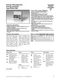
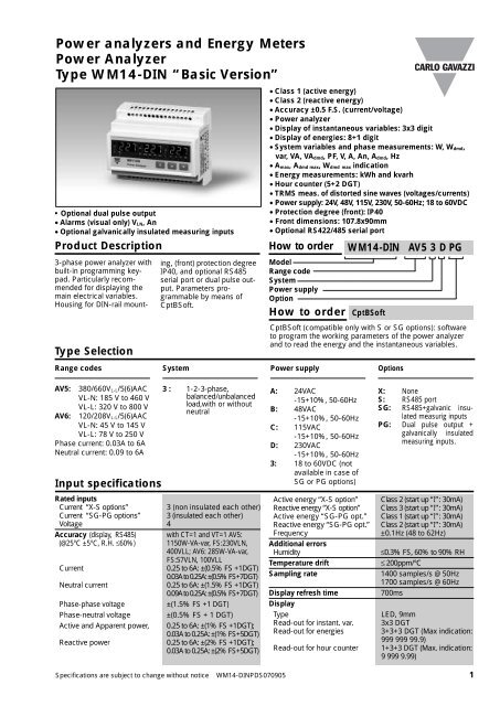
<strong>Power</strong> <strong>analyzers</strong> <strong>and</strong> <strong>Energy</strong> <strong><strong>Meter</strong>s</strong><strong>Power</strong> AnalyzerType WM14-DIN “Basic Version”• Optional dual pulse output• Alarms (visual only) V LN, An• Optional galvanically insulated measuring inputsProduct DescriptionType SelectionRange codes3-phase power analyzer withbuilt-in programming keypad.Particularly recommendedfor displaying themain electrical variables.Housing for DIN-rail mounting,(front) protection degreeIP40, <strong>and</strong> optional RS485serial port or dual pulse output.Parameters programmableby means ofCptBSoft.System• Class 1 (active energy)• Class 2 (reactive energy)• Accuracy ±0.5 F.S. (current/voltage)• <strong>Power</strong> analyzer• Display of instantaneous variables: 3x3 digit• Display of energies: 8+1 digit• System variables <strong>and</strong> phase measurements: W, W dmd,var, VA, VA dmd, PF, V, A, An, A dmd, Hz• A max, A dmd max, W dmd max indication• <strong>Energy</strong> measurements: kWh <strong>and</strong> kvarh• Hour counter (5+2 DGT)• TRMS meas. of distorted sine waves (voltages/currents)• <strong>Power</strong> supply: 24V, 48V, 115V, 230V, 50-60Hz; 18 to 60VDC• Protection degree (front): IP40• Front dimensions: 107.8x90mm• Optional RS422/485 serial portHow to orderModelRange codeSystem<strong>Power</strong> supplyOptionHow to order<strong>Power</strong> supplyWM14-DIN AV5 3 D PGXCptBSoftCptBSoft (compatible only with S or SG options): softwareto program the working parameters of the power analyzer<strong>and</strong> to read the energy <strong>and</strong> the instantaneous variables.OptionsAV5: 380/660V L-L/5(6)AACVL-N: 185 V to 460 VVL-L: 320 V to 800 VAV6: 120/208V L-L/5(6)AACVL-N: 45 V to 145 VVL-L: 78 V to 250 VPhase current: 0.03A to 6ANeutral current: 0.09 to 6AInput specifications3 : 1-2-3-phase,balanced/unbalancedload,with or withoutneutralRated inputsCurrent “X-S options”3 (non insulated each other)Current “SG-PG options” 3 (insulated each other)Voltage 4Accuracy (display, RS485) with CT=1 <strong>and</strong> VT=1 AV5:(@25°C ±5°C, R.H. ≤60%) 1150W-VA-var, FS:230VLN,400VLL; AV6: 285W-VA-var,FS:57VLN, 100VLLCurrent0.25 to 6A: ±(0.5% FS +1DGT)0.03A to 0.25A: ±(0.5%FS+7DGT)Neutral current0.25 to 6A: ±(1.5% FS +1DGT)0.09A to 0.25A: ±(0.5%FS+7DGT)Phase-phase voltage±(1.5% FS +1 DGT)Phase-neutral voltage ±(0.5% FS + 1 DGT)Active <strong>and</strong> Apparent power, 0.25 to 6A: ±(1% FS +1DGT);0.03A to 0.25A: ±(1% FS+5DGT)Reactive power0.25 to 6A: ±(2% FS +1DGT);0.03A to 0.25A: ±(2% FS+5DGT)A: 24VAC-15+10%, 50-60HzB: 48VAC-15+10%, 50-60HzC: 115VAC-15+10%, 50-60HzD: 230VAC-15+10%, 50-60Hz3: 18 to 60VDC (notavailable in case ofSG or PG options)Active energy “X-S option”Reactive energy “X-S option”Active energy “SG-PG opt.”Reactive energy “SG-PG opt.”FrequencyAdditional errorsHumidityTemperature driftSampling rateDisplay refresh timeDisplayTypeRead-out for instant. var.Read-out for energiesRead-out for hour counterX: NoneS: RS485 portSG: RS485+galvanic insulatedmeasurig inputsPG: Dual pulse output +galvanically insulatedmeasuring inputs.Class 2 (start up “I”: 30mA)Class 3 (start up “I”: 30mA)Class 1 (start up “I”: 30mA)Class 2 (start up “I”: 30mA)±0.1Hz (48 to 62Hz)≤0.3% FS, 60% to 90% RH≤ 200ppm/°C1400 samples/s @ 50Hz1700 samples/s @ 60Hz700msLED, 9mm3x3 DGT3+3+3 DGT (Max indication:999 999 99.9)1+3+3 DGT (Max. indication:9 999 9.99)Specifications are subject to change without notice WM14-DINPDS070905 1
WM14-DINInput specifications (cont.)MeasurementsCoupling typeCrest factorCurrent, voltage, power,power factor, frequency,energy, TRMS measurementof distorted waves.Direct< 3, max 10A peakInput impedance(X-S options)380/660V L-L (AV5) 1 MΩ ±5%120/208V L-L (AV6) 453 KΩ ±5%Current ≤ 0.02ΩInput impedance(PG-SG options)380/660V L-L (AV5) 1 MΩ ±1%120/208V L-L (AV6) 1 MΩ ±1%Current ≤ 0.02ΩFrequencyOverload protectionContinuos voltage/currentFor 500ms: voltge/current48 to 62 Hz1.2 F.S.2 Un/36ARS485 Serial Port SpecificationsRS422/RS485 (on request)TypeConnectionsAddressesProtocolMultidropbidirectional (static <strong>and</strong>dynamic variables)2 or 4 wires, max. distance1200m, termination directlyon the instrument1 to 255, key-pad selectableMODBUS/JBUSData (bidirectional)Dynamic (reading only)Static (writing only)Data formatBaud-rateSystem, phase variables <strong>and</strong>energiesAll configuration parameters1 bit di start , 8 data bit,no parity, 1 stop bit9600 bit/sCptBSoft software: parameter programming <strong>and</strong> reading dataCptBSoftMulti language software toprogram the workingparameters of the poweranalyzer <strong>and</strong> to read theenergies <strong>and</strong> theinstantaneous variables.The program runs underWindows 95/98/98SE/2000/NT/XP.Working modeData accessTwo different workingmodes can be selected:- management of a localRS485 network;- management ofcommunication from a singleinstrument to PC (RS232);By means of RS485serial port.Dual pulse outputDigital outputs (on request)Pulse outputsNumber of outputsNumber of pulsesOutput type2 (one for kWh one for kvarh)From 0.01 to 999 incompliance with thefollowing formula:[Psys max (kW orkvar)*pulses (pulses/kWhor kvarh)]
WM14-DINSoftware functionsPassword Numeric code of max. 3digits; 2 protection levelsof the programming data1st levelPassword “0”, noprotection2nd level Password from 1 to 999,all data are protectedSystem selection3-phase with/without n, unbal.3-phase balanced3-phase ARON, unbalanced2-phaseSingle phaseTransformer ratioCT 1 to 999VT 1.0 to 99.9FilterOperating rangeFiltering coefficient 1 to 16Filter actionDisplaying3-phase system with neutral0 to 100% of the inputdisplay scaleMeasurements, alarms,serial out. (fundamental var: V,A, W <strong>and</strong> their derived ones).Up to 3 variables per pagePage 1: V L1, V L2, V L3Page 2: V L12, V L23, V L31Page 3: A L1, A L2, A L3Page 4: A L1 dmd, A L2 dmd,A L3 dmdAlarmsResetPage 5: An, An AlarmPage 6: W L1, W L2, W L3Page 7: PF L1, PF L2, PF L3Page 8: var L1, var L2, var L3Page 9: VA L1, VA L2, VA L3Page 10: VA ∑, W ∑, var ∑Page 11: VA dmd, W dmd, HzPage 12: W dmd max (*)Page 13: Wh (*)Page 14: varh (*)Page 15: VL-L ∑, PF ∑,VLN AlarmPage 16: A max (*)Page 17: A dmd max (*)Page 18: hour counter (*)(*) = These variables arestored in EEPROM when theinstrument is switched offProgrammable, for the VL∑<strong>and</strong>An (neutral current).Note: the alarm is only visual,by means of LED on the frontof the instrument.Independentalarm (VL∑, An)max: A dmd, W dmdall energies (Wh, varh) <strong>and</strong>hour counter<strong>Power</strong> Supply SpecificationsAuxiliary power supply230VAC-15 +10%, 50-60Hz115VAC-15 +10%, 50-60Hz48VAC-15 +10%, 50-60Hz<strong>Power</strong> consumption24VAC-15 +10%, 50-60Hz18 to 60VDCAC: 4.5 VADC: 4WGeneral SpecificationsOperatingtemperatureStoragetemperatureInstallation categoryInsulation (for 1 minute)0° to +50°C (32 to 122°F)(RH < 90% non condensing)-10° to +60°C (14 to 140°F)(RH < 90% non condensing)Cat. III (IEC 60664, EN60664)4000VAC, 500VDCbetween mesuringinputs <strong>and</strong> power supply.500VAC/DC betweenmesuring inputs <strong>and</strong> RS485.4000VAC, 500VDC betweenpower supply <strong>and</strong> RS485Dielectric strength4000 VAC (for 1 min)EMCEmissions EN50084-1 (class A)residential environment,commerce <strong>and</strong> light industrySpecifications are subject to change without notice WM14-DINPDS070905 3
WM14-DINGeneral Specifications (cont.)EMC (cont.)HousingMax cable cross sect. area 2.5 mm 2Immunity EN61000-6-2 (class A) Dimensions (WxHxD)industrial environment. MaterialPulse voltage (1.2/50µs)EN61000-4-5Safety st<strong>and</strong>ardsIEC60664, EN60664 MountingApprovalsCE, (cURus, CSA only “X”<strong>and</strong> “S” options)Protection degreeConnections 5(6) AScrew-typeWeight107.8 x 90 x 64.5 mmABSself-extinguishing: UL 94 V-0DIN-railFront: IP40 (st<strong>and</strong>ard)Connections: IP20Approx. 400 g (pack. incl.)Display pagesDisplay variables in 3-phase systems (in a 3-phase system with neutral)No 1 st variable 2 nd variable 3 rd variable Note1 V L1 V L2 V L32 V L12 V L23 V L31 Decimal point blinking on the rightof the display3 A L1 A L2 A L34 A L1 dmd A L2 dmd A L3 dmd dmd = dem<strong>and</strong> (integration timeselectable from 1 to 30 minutes)5 An AL.n AL.n if neutral current alarm isactive6 W L1 W L2 W L3 Decimal point blinking on the rightof the display if generated power7 PF L1 PF L2 PF L38 var L1 var L2 var L3 Decimal point blinking on the rightof the display if generated power9 VA L1 VA L2 VA L310 VA system W system var system11 VA dmd W dmd Hz dmd = dem<strong>and</strong> (integration time(system) (system) (system) selectable from 1 to 30 minutes)12 W dmd MAX Maximum sys power dem<strong>and</strong>13 Wh (MSD) Wh Wh (LSD) The total indication is given inmax 3 groups of 3 digits.14 varh (MSD) varh varh (LSD) The total indication is given inmax 3 groups of 3 digits.15 V LL system AL.U PF system AL.U= is activated only if one ofVLN is not within the set limits.16 A MAX max. current among the three phases17 A dmd max max. dmd current among the three phases18 h hour counterMSD: most significant digitLSD: least significant digit1) Example of kWh visualization:This example is showing 15 933 453.7 kWh2) Example of kvarh visualization:This example is showing 3 553 944.9 kvarh4 Specifications are subject to change without notice WM14-DINPDS070905
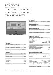
WM14-DINWaveform of the signals that can be measuredFigure ASine wave, undistortedFundamental content 100%Harmonic content 0%A rms = 1.1107 | A |Figure BSine wave, indentedFundamental content 10...100%Harmonic content 0...90%Frequency spectrum: 3rd to 16th harmonicAdditional error:
WM14-DINUsed calculation formulas (cont.)<strong>Energy</strong> meteringWhere:i = considered phase (L1, L2 or L3)P = active powerQ = reactive powert 1, t 2 = starting <strong>and</strong> ending time points of consumption recordingn = time unit∆t = time interval between two successive power consumptionsn 1, n 2 = starting <strong>and</strong> ending discrete time points of consumption recordingWiring diagramsFig. 1Fig. 2Fig. 3CT connection3CT <strong>and</strong> 3VT connectionARON <strong>and</strong> VT connectionFig. 4Fig. 5 Fig. 62-phase connection3-phase load balanced connection1-phase connectionNOTE: Only for “PG” <strong>and</strong> “SG” options: the current measuring inputs are galvanically insulated<strong>and</strong> therefore they can be connected to ground singly.NOTE: For all models except for “PG” or “SG” the current inputs can be connected to the linesONLY by means of current transformers. The direct connection is not allowed.6 Specifications are subject to change without notice WM14-DINPDS070905
WM14-DINRS485 port connectionsDual pulse output connections[a] [b] [c]GNDT1011GNDT1011GNDRS485 RS232RX+ 12 RX+ 12TX+PCPulse 1Pulse 2Fig. 8RX-13RX-13TX-TX+TX-1415TX+TX-1415RX+RX-4-wireconnection[a] [b] [c]GNDT1011GNDT1011GNDRS485 RS232RX+ 12 RX+ 12TX+PC21 4312 6 13 7 1415 8 9131415131415RX-TX+TX-RX-TX+TX-TX-RX+RX-2-wireconnectionNL+-Fig. 7: a-Last instrument; b-1...n Instrumentc-RS485/232 serial converterFront Panel Description211. Key-padTo program the configuration parameters <strong>and</strong> the display ofthe variables.SKey to enter programming <strong>and</strong> confirm selections;▲Keys to:- programme values;- select functions;- display measuring pages.▲2. DisplayLED-type with alphanumeric indications to:- display configuration parameters;- display all the measured variables.Dimensions <strong>and</strong> Panel Cut-out90mm44mm45mm108,5mm107,8mm32,2mm50,1mm64,5mmSpecifications are subject to change without notice WM14-DINPDS070905 7