WattSoft3 DS - Meter Manager
WattSoft3 DS - Meter Manager
WattSoft3 DS - Meter Manager

You also want an ePaper? Increase the reach of your titles
YUMPU automatically turns print PDFs into web optimized ePapers that Google loves.
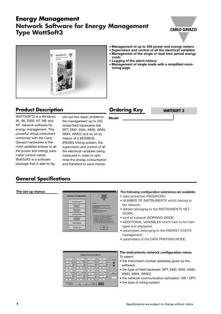
Energy Management<br />
Network Software for Energy Management<br />
Type <strong>WattSoft3</strong><br />
• Management of up to 255 power and energy meters<br />
• Supervision and control of all the electrical variables<br />
• Management of the single or dual time period energy<br />
costs<br />
• Logging of the alarm history<br />
• Management of single loads with a simplified monitoring<br />
page<br />
Product Description<br />
WATTSOFT3 is a Windows<br />
95, 98, 2000, NT, ME and<br />
XP network software for<br />
energy management. This<br />
powerful virtual instrument<br />
combined with the Carlo<br />
Gavazzi hardwares is the<br />
most updated answer to all<br />
the power and energy parameter<br />
control needs.<br />
<strong>WattSoft3</strong> is a software<br />
package that is able to fig-<br />
ure-out two basic problems:<br />
the management up to 255<br />
mixed field hardwares like<br />
SPT, EM2, EM4, WM2, WM3,<br />
WM4, WM22 and so on by<br />
means of a MODBUS<br />
(RS485) linking system; the<br />
supervision and control of all<br />
the electrical variables being<br />
measured in order to optimise<br />
the energy consumption<br />
and therefore to save money.<br />
Ordering Key WATTSOFT 3<br />
Model<br />
General Specifications<br />
The set-up menus<br />
The following configuration submenus are available:<br />
• data protection PASSWORD;<br />
• NUMBER OF INSTRUMENTS which belong to<br />
the network;<br />
• details belonging to the INSTRUMENTS NET-<br />
WORK;<br />
• kind of network WORKING MODE;<br />
• ADDITIONAL VARIABLES which hare to be managed<br />
and displayed;<br />
• parameters belonging to the ENERGY COSTS<br />
management;<br />
• parameters of the DATA PRINTING MODE.<br />
The instruments network configuration menu<br />
To select:<br />
• the instrument number (address) given by the<br />
software;<br />
• the type of field hardware: SPT, EM2, EM4, WM2,<br />
WM3, WM4, WM22;<br />
• the network communication activation: ON / OFF;<br />
• the type of wiring system<br />
1 Specifications are subject to change without notice
General Specifications (cont.)<br />
The alarm set-points menu<br />
The available parameters are:<br />
• label programming;<br />
• list of network available instruments;<br />
• type of set-point variable;<br />
• type of alarms<br />
• SW and HW alarm working mode<br />
Other characteristics<br />
This flexible software is capable, by<br />
means of various setting menus, to<br />
be configured so as to meet different<br />
applications.<br />
It is possible to manage and display<br />
all the measured electrical parameters. A<br />
powerful alarm control is available for each<br />
measurement. The energy costs can be<br />
calculated according to various references like:<br />
time, power and energy rates.<br />
Data pages<br />
Total data<br />
The main page “TOTAL DATA” shows the execution<br />
status of the measurements, indicating the<br />
list of all the variables with the measurement<br />
results; giving the possibility to reset the total<br />
consumed energies, the alarms, the hour counter<br />
and allowing the operator to enter various<br />
graphs: cost, energy, power, current, voltage,<br />
power factor.<br />
Single data<br />
The page “SINGLE DATA” shows the details of a<br />
group of up to six instruments, indicating: the<br />
number of the displayed monitoring page, the<br />
labels of the instruments “USERS”; the list of all<br />
the variables with the measurements results and<br />
those measurements indicating the presence of<br />
alarm status; the user is allowed to enter every<br />
single data page and to see where an alarm condition<br />
has been detected by Wattsoft3.<br />
Total data graph<br />
This monitoring page can be divided into four parts:<br />
- on the upper area it is possible to select the<br />
instrument at which the graph belongs to and the<br />
type of time base needed to be displayed; this<br />
page also shows the alarm status of the system,<br />
the user label, the wiring system of the instrument,<br />
the current date and time;<br />
- on the middle left, the graph of up to four variables;<br />
- on the middle right, all the info connected to the<br />
graph (including zoom functions and selection<br />
between automatic or manual axis range);<br />
- on the lower right, manual printing enabling of the<br />
graph and possibility to go back to the TOTAL DATA<br />
page.<br />
Specifications are subject to change without notice 2