ICT Cooling Towers - Evapco
ICT Cooling Towers - Evapco
ICT Cooling Towers - Evapco

You also want an ePaper? Increase the reach of your titles
YUMPU automatically turns print PDFs into web optimized ePapers that Google loves.
Selection Procedure<br />
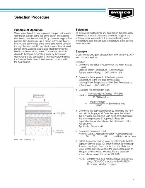
Principle of Operation<br />
Warm water from the heat source is pumped to the water<br />
distribution system at the top of the tower. The water is<br />
distributed over the wet deck fill by means of large orifice<br />
nozzles. Simultaneously, air is drawn in through the air<br />
inlet louvers at the base of the tower and travels upward<br />
through the wet deck fill opposite the water flow. A small<br />
portion of the water is evaporated which removes the<br />
heat from the remaining water. The warm moist air is<br />
drawn to the top of the cooling tower by the fan and<br />
discharged to the atmosphere. The cool water drains to<br />
the basin at the bottom of the tower and is returned to<br />
the heat source.<br />
PRINCIPLE OF OPERATION<br />
Selection<br />
To size a cooling tower for any application it is necessary<br />
to know the flow rate of water to be cooled in gpm, the<br />
entering water temperature, the desired leaving water<br />
temperature, and the wet bulb temperature at the cooling<br />
tower location.<br />
Example<br />
Given: to cool 200 gpm of water from 97°F to 85°F at 76°F<br />
wet bulb temperature.<br />
Selection:<br />
1. Determine the range through which the water is to be<br />
cooled:<br />
Entering Water Temperature – Leaving Water<br />
Temperature = Range (97° – 85° = 12°)<br />
2. Determine the approach of the leaving water<br />
temperature to the wet bulb temperature:<br />
Leaving Water Temperature – Wet Bulb Temperature<br />
= Approach (85° – 76° = 9°)<br />
3. Calculate the nominal ton load:<br />
Load =<br />
flow rate (gpm) X range (°F) X 500<br />
15,000 btuh/ton<br />
= 200 X 12 X 500 = 80 nominal tons<br />
15,000<br />
4. Determine the application factor by turning to the 76°F<br />
wet bulb table, page 10. Enter the top of the table in<br />
the 12° range column and read down to the horizontal<br />
line which represents 9° approach. Read the<br />
application factor which lies at the intersection of the<br />
two columns.<br />
Application Factor = .81<br />
5. Determine Corrected Load:<br />
Nominal Load X Application Factor = Corrected Load<br />
80 X .81 = 64.8 corrected tons<br />
6. Select the proper cooling tower by referring to the <strong>ICT</strong><br />
capacity curves, page 12. Enter the chart at the design<br />
flow and read up to the corrected ton line. Select a<br />
tower whose curve lies above the intersection point of<br />
the gpm and corrected ton lines. For the example<br />
shown above, select the model <strong>ICT</strong> 4-76.<br />
NOTE: Contact your local representative to receive a<br />
copy of EVAPCO’s exclusive EVAPSPEC ® II<br />
Computer Selection Program.<br />
7