Modular scaffolding <strong>RUX</strong>-VARIANT2 Special provisionsModular scaffolding <strong>RUX</strong>-VARIANT2 Special provisions2.3.5 Guard railsThe DIN 4420 , part 1 or part 4 (HD 1000) specifications apply to the side rails (barriers). The componentsintended for this area of the scaffold are to be used. Only in exceptional cases are components such as steeltubes connected by means of couplers, as well as battens and planks as per DIN 4420, part 1 to be installed.2.3.6 StiffeningScaffolds must be stiffened. On facade scaffolds, the outer vertical plane parallel to the facade is to bestiffened by diagonals arranged either continuously or in tower form. In doing so, a maximum of five bays areto be assigned to one diagonal. Ledgers are to be fitted at base plate height or, in the case of base jacks, abovethe adjustor nut, in those bays where a diagonal connects. When tying facade scaffolds appropriately, and whenusing system decking, the fitting of longitudinal ledgers at decking level can be dispensed with in those baysin which no diagonals are connected. Facade scaffolds constructed from <strong>RUX</strong>-VARIANT modular scaffoldingwith non-system timber planks must always be erected with longitudinal ledgers at deck level. It may also benecessary to install horizontal diagonals at deck level on such structures. Scaffolds with a width of more than1.0 m must always be fitted with ledgers at deck level.2.3.7 DeckingThe decking (planks) is to be secured against unintentional displacement2.3.8 IdentificationThe components described in Chapter 2.1.4 are only to be used when they are marked with the manufacturer’s symbol andthe two last digits of the year in which they were manufactured. Components may also be used which are inline with these instructions on erection and use and which were manufactured, without the means of identificationmentioned in this chapter, prior to the publication of this manual.2.3.9 Verification of stabilityThe stability of scaffolds erected with the components described in Chapter 2.1.4 must be verified in eachindividual case or a structural type analysis must be submitted. The verification of stability is deemed to havebeen provided for the standard designs described in this manual.2.3.11 Ivergence from standard designsWhen the scaffolding system is used for scaffolds which diverge from the standard designs illustrated in theseinstructions for erection and use, then such divergences must be assessable in accordance with the technicalconstruction regulations and/or be verified in individual cases. In doing so, other tying patterns may also beemployed. The increased loads, e.g. emanating from– the increase in self-weight,– the increase in the surface influenced by wind forces,– increased live loadsare to be verified right into the ties and into the set-up plane (ground level). The influence of lifts and other liftinggear is also to be taken into account in the event that they are not operated independently of the scaffold.2.3.12 Provisions for verifiction in individual casesFacade scaffoldsThe untied vertical frames, or rows of standards, contained in tied horizontal lifts are held elastically in placeby system planks (decking) to prevent horizontal displacement at right angles to the facade. At a horizontal tiespacing of two bay lengths, this stiffening effect can be substituted, to a certain extent, by a movement spring.At bay lengths 3.00 m the spring stiffness c dependent upon the decking used, is– solid timber and steel planks c = 0.45 kN/cm,– aluminium planks c = 0.75 kN/cm,when the fitting of longitudinal ledgers at deck level is dispensed with.When system planks and longitudinal ledgers are used at deck level, the horizontal spring stiffness c cangenerally be set at c= 1.5 kN/cm for calculation purposes.2.3.10 Standard designsScaffolds are deemed to be of standard design within the context of these instructions for erection and usewhen constructed along the lines illustrated under point 4. They are dimensioned to cope with live loads as perDIN 4420. The standard designs are only to be used without further verification when the actual live loadsincurred are not larger than those listed in the DIN 4420 standard.<strong>Instructions</strong> for erection and use valid only for the original <strong>RUX</strong>-VARIANT modular scaffolding system from <strong>RUX</strong> GmbH, Hagen, Germany!<strong>Instructions</strong> for erection and use valid only for the original <strong>RUX</strong>-VARIANT modular scaffolding system from <strong>RUX</strong> GmbH, Hagen, Germany!26 <strong>RUX</strong> GmbH · Phone +49 2331 4709-0 · Fax +49 2331 4709-202 · Mail rux@rux.de<strong>RUX</strong> GmbH · Phone +49 2331 4709-0 · Fax +49 2331 4709-202 · Mail rux@rux.de 27
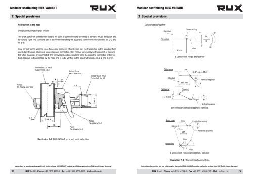
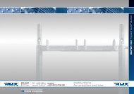
Modular scaffolding <strong>RUX</strong>-VARIANT2 Special provisionsModular scaffolding <strong>RUX</strong>-VARIANT2 Special provisionsVerification at the nodeDesignation and structural systemThe short bars from the standard tube to the point of connection are assumed to be yield, thrust, deflection andtorsionally rigid. The standard tube is to be verified taking the eccentric connections into account (Ill. 2-2 andIll. 2-3).General statical systemStandardElevationSwivel-springOnly normal forces, vertical cross forces and moments of deflection may be transmitted in the standard tubeand ledger/transom plane in a ledger/transom connection. Only normal forces may be transferred or transmittedwhen diagonals are connected. The transverse bending, resulting from the eccentric connection of the verticaldiagonal, is transfmitted by the node and is to be verified in the ledgers/transoms (Ill. 2-2 and Ill. 2-3).Ledgera) Connection: Riegel-StänderrohrStandard S235 JRG2Tube Ø 48.3 x 3.2Ledger-hookEN-GJMW-450-7Ledger S235 JRG2Tube Ø 48.3 x 3.2Side viewStandardLinkVertical diagonalFlangeEN-GJMW-360-12WOverviewStandardVertical diagonalb) Connection: Vertical diagonal / standardPawlEN-GJMW-450-7WedgeEN-GJMW-450-7Side viewStändardLinkLongitudinal springHorizontal diagonalIllustration 2-2 <strong>RUX</strong>-VARIANT node and prefix definitionLinkOverviewLedgerc) Connection: Horizontal diagonal / standardIllustration 2-3 Structural (statical) systems<strong>Instructions</strong> for erection and use valid only for the original <strong>RUX</strong>-VARIANT modular scaffolding system from <strong>RUX</strong> GmbH, Hagen, Germany!<strong>Instructions</strong> for erection and use valid only for the original <strong>RUX</strong>-VARIANT modular scaffolding system from <strong>RUX</strong> GmbH, Hagen, Germany!28<strong>RUX</strong> GmbH · Phone +49 2331 4709-0 · Fax +49 2331 4709-202 · Mail rux@rux.de<strong>RUX</strong> GmbH · Phone +49 2331 4709-0 · Fax +49 2331 4709-202 · Mail rux@rux.de29