
Create successful ePaper yourself
Turn your PDF publications into a flip-book with our unique Google optimized e-Paper software.
HOW CUTTING SPEED AFFECTS CUT QUALITYCutting speed just rightCutting speed too fastCutting speed too slowchanges cause a reduction in the energyof the plasma jet.To eliminate high speed dross:• Check the nozzle first for signsof wear (gouging, oversize or ellipticalorifice)• Decrease the cutting speed in5-in./min increments• Decrease the standoff in 1 ⁄16-inchincrements or 5-V increments• Increase the amperage (do notexceed 95 percent of the nozzle orificerating)Top spatter dross. Top spatter isan accumulation of re-solidifiedmetal that sprays along the top of thecut piece. It is usually very easy toremove. A worn nozzle, excessivecutting speed, or a high standoff isusually the cause. It is caused by theswirling flow of the plasma jet, whichat a certain angle of attack flingsmolten material out in front of thekerf rather than down through it.To eliminate top spatter:• Check the nozzle for signs ofwear• Decrease the cutting speed in5-in./min increments• Decrease the standoff in 1 ⁄16-inchincrements or 5-V incrementsFinding the dross-free windowbetween high- and low-speed drossis the key to minimizing secondaryoperations on plasma-cut pieces.The window varies with plasma gasused. For example, nitrogen and airplasma gases have a relatively narrowdross-free window on carbonsteels, while oxygen plasma has awider dross-free window. Oxygenplasma gas reacts with carbon steelto produce a finer spray of moltenmetal, each droplet having a lowersurface tension. This molten spray ismore easily ejected from the kerf.The dross-free window is alsoaffected by material type. For instance,cold-rolled steels cut morecleanly than hot-rolled, and pickledsteels cut cleaner than non-pickled.Tuning the speed There are twogood ways to judge the optimum cuttingspeed. The first method involvesmaking a series of test cuts at variouscutting speeds and choosing thespeed that produces the cleanestcut. Lag lines—small ridges in thesurface of the cut—indicate use ofproper or improper cutting speed.Slow cutting speeds produce verticallag lines that are perpendicular tothe plane of the plate. Fast cuttingspeeds make slanted s-shaped laglines that run parallel to the platealong the bottom edge. Many operatorshave the tendency to slow themachine down at the first appearanceof dross, but often an increasein speed is necessary.The second method to judge cuttingspeed is to watch the arc duringthe cut and dynamically change thespeed to produce the optimum arccharacteristics. To do this, observethe angle of the arc as it exits thebottom of the workpiece. When cuttingwith air plasma gas, the arcshould be vertical as it exits the bottomside of the cut. With nitrogen orargon/hydrogen, a slight trailing arcis best. With oxygen plasma gas, thebest cut speed is one that results in aslight leading arc.November 2000 ■ Welding Design and Fabrication7
CLASSROOMWritten By: David J. Cook<strong>Centricut</strong> Technical Services DirectorTips and techniquesfor mechanized plasmacutting: PiercingHere’s a pop quiz for the PACsupervisor, industrial engineer, purchasingagent, or maintenanceman:What is the number-one cause ofpremature parts failure in plasmatorches?a. Inadequate plasma-gas flowb. Inadequate coolant flowc. Machine malfunctiond. Improper piercing techniqueIf you answered a, b, or c, you getpartial credit. If you answered d,you’re correct and on your way tosaving money and decreasingdowntime on the plasma-cuttingmachine.Piercing too close to the materialis the most common cause of prematureconsumable-parts failure.The problem sounds simple enoughto correct, yet it persists in many cuttingoperations. One reason is thelack of good technical training forPAC-machine operators. Armed witha fundamental understanding of theprocess and a couple of simple tipsand techniques, an operator willspend more time cutting parts andless time changing consumables.What happens during a pierce?When the torch fires, a high-voltagespark combined with a limitedamount of DC current produces apilot arc at the torch. This pilot arcprojects from the end of the torch ina steady, white-blue arc. The pilotarc forms an electrical path from thecathode—the electrode in thetorch—to the anode—the conductiveworkpiece. If the torch is withintransfer distance, the arc will transferto the metal and begin to pierce.Every torch has a maximum transferdistance that is also its maximumpierce height. If the torch is higherthan this distance it will pilot in theair; if it is lower, it will transfer andbegin to pierce.Stage 1. The transferred arcinstantly heats the workpiece to itsmelting point and begins blowing themolten material away. In the initialstage of the pierce, the molten metalsprays out radially from the piercepoint over the top of the plate in ashower of sparks.Stage 2. As the plasma jet penetratesdeeper into the material, around-bottomed hole forms. Thishole begins to direct the moltenspray upward toward the torch.Stage 3. Once the arc breaksthrough the bottom of the plate, thesparks and molten material exit outof the pierced hole. When the pierceis complete and the arc has grownto its full strength, the torch beginsto move. If the torch moves toosoon, the arc may not fully penetratethe material. If the torch delays toolong, the arc will continue to removematerial, enlarging the hole until thearc extinguishes.Piercing problemsThe most common piercing problemsare double arcing, bridging,and snuffing. These occur duringthe second stage of piercing when afountain of molten metal is sprayedback up at the torch. Under normalconditions, the arc column is controlledand focused by a swirling vortexof gas as it passes from the electrodethrough the nozzle to theplate. This boundary layer of gasprevents the arc from contacting thecopper nozzle. If the arc does contactthe nozzle it will cut it as it doesto any conductive metal.Double arcing describes any arcingthat occurs secondarily to themain cutting/piercing arc. It occurswhen current flows through the nozzle,or through another conductivepath, to the plate other than directlythrough the arc column. This canoccur due to low plasma-gas flow,12Welding Design and Fabrication ■ November 2000
Stage 1 Stage 2 Stage 3 Pierce too lowexcessive amperage, or a seriousdisturbance in the plasma jet. Sucha disturbance happens when thetorch is piercing too close to theplate. The spray of electrically conductivemetal disturbs the plasmagasjet by disrupting the electric fieldsurrounding the arc and causing thearc column to grow. It’s theorizedthat multiple arc paths developthrough these tiny bits of metal,pulling the arc out of its axial-symmetricpath. If the arc is pulled intothe sidewall of the nozzle, it causesa gouge, nick, or sometimes a symmetricalchamfer along the exit orifice.Damage to the nozzle leads toserious cut-quality problems such asexcess bevel angle, dross, and failureto penetrate the material.Bridging, a more extreme form ofdouble arcing, occurs if the moltenmaterial builds up in a puddle thatcontacts both torch and plate. Sincethis puddle is electrically conductive,it provides a short circuit to theworkpiece. The arc sees a path oflower electrical resistance and takesit, usually causing failure of theshield and nozzle. Even state-ofthe-artelectrically isolated coppershields are not immune to this typeof failure. Once the shield contactsa ball of molten material it is at thesame potential as the plate, thereforethe arc will conduct through theshield and cause it to fail.Plasma-gas snuffing, the mostextreme form of double arcing,occurs when the torch begins topierce with the torch nozzle or shieldpressed against the plate. For example,if the automatic torch-heightcontrol finds its initial height bypushing against the plate, and theplate is bowed or thin enough to bepushed down, then the retraction ofthe torch will not set the correct initialheight. The torch will fail to clearthe plate because the plate followsthe torch back up to its initial heightsetting. This often occurs in underwatercutting when the operator cannotsee the front end of the torch.Snuffing of the plasma gas leads touncontrolled double-arcing in theplasma chamber, causing catastrophicfailure of the electrode,nozzle, and shield.Tips and techniques• Pierce high and cut low—Therule of thumb is to pierce at 1.5-2Xthe cut height or at the maximumtransfer distance. Piercing high preventsdouble arcing, bridging, andsnuffing.• Use a creeping pierce—If yourCNC is capable, program it to slowlymove the torch during the pierceoperation to form a “rooster tail” ofmolten material to miss the front endof the torch.• Don’t “eyeball” the pierceheight—Use the initial height sensingif it’s available. Manual piercingis usually not recommended; evenexperienced operators lack a perfectlycalibrated eye.• Don’t pierce beyond system limits—Piercerating is typically 1/4 thecut rating.• Avoid piercing—Whenever possible,use chain cutting or edgestarting to reduce the number ofpierces.Special TechniquesExperienced operators sometimesuse two special tricks forpiercing through thick plate.WARNING: Don’t try these techniquesunless you have an experiencedoperator familiar with safeoperation of the machine.Double shot–This techniqueinvolves blowing through the plate intwo or more successive piercesrather than one. The first pierceestablishes a round-bottomed holeabout halfway through the plate. Theoperator then manually jogs thetorch slightly toward the edge of thehole and pierces again. The secondshot blows through the material asthe “rooster tail” of molten metal isdeflected away from the torch.Rising pierce–To perform thismanual pierce, the operator bringsthe torch down to the plate with thepilot arc on. As soon as transferoccurs, he raises the torch to stretchthe arc to as high as 1 inch abovethe plate. As the plasma jet blowsthrough the plate, the operator lowersthe torch to normal cuttingheight. This protects the torch andshield, but shortens electrode andnozzle life.November 2000 ■ Welding Design and Fabrication13
CLASSROOMWritten By: David J. Cook<strong>Centricut</strong> Technical Services DirectorTroubleshootingPAC Systems:Starting ProblemsWARNING! PAC system maintenanceand repair should only beattempted by those skilled in electricaltroubleshooting. PAC systemsuse high voltage and direct-current(DC) electricity. Electric shock caninjure or kill.Symptom: The torch fails to initiatethe cutting arc when all otherconditions for normal operation arecorrect—power supply energized,safety and parts-in-place interlockssatisfied, gas pre-flow at torch, andtorch within transfer distance.The sequence of operation for thetypical PAC system is as follows: Thestart-cut signal is sent to the powersupply to energize the system. Asolenoid opens, allowing gas flow tothe torch. The pilot-arc relay latches,activating open-circuit voltage (OCV)between the nozzle (+) and the electrode(-). A high-frequency (HF)spark (see illustration 1) is suppliedto the torch by a high-voltage generatorwith 3,000-10,000 V AC output.The high-frequency generator usuallyincludes a high-voltage transformer,capacitors, spark-gapassembly, and coil.The high-frequency spark ionizesthe gas flowing through the torch,making it electrically conductive.The ionized gas allows current flowbetween the electrode and nozzle.This current is limited to 20-40 A DCby the pilot resistor. The arc blowsout of the orifice and reattaches tothe face of the nozzle, forming a pilotarc (see illustration 2).The pilot arc forms the electricalpathway to the workpiece. If thetorch is within transfer distance, usually0.25 to 0.50 inch from thematerial, the pilot arc will transfer tothe plate since the plate is connectedto the positive pole of the DC circuitand is not limited by a resistor(see illustration 3). A current-sensingcircuit senses arc transfer, shutsoff the HF generator, and opens thepilot-arc relay.In simple terms, the torch needsthree ingredients to form a pilot arc:plasma gas, DC power, and AC highfrequency. With any of these ingredientsmissing, the torch will not fire,transfer, or cut.Troubleshooting startingproblemsWhen starting problems occur,the operator should first evaluate thepilot arc. He raises the torch severalinches above the material to providea good, clear view of the torch.He then signals the torch to fire.After several seconds of gas flow, apilot arc should form at the torch. Ahealthy pilot arc will sustain itself inthe air for several seconds. He looksfor an arc with a bright white-bluecolor that projects 0.25-0.50 inchfrom the end of the nozzle. The arcshould not spit and sputter or soundraspy; it should be smooth andsteady. He should test the pilot arca number of times in the air to see ifthe condition repeats.Problem 1: Hard StartingIf the pilot arc spits and sputtersbut fires intermittently, the problemmay be hard starting. Hard startingoccurs when the HF struggles tobreak down the high-pressurebarrier between electrode andnozzle. This can be caused byinsufficient HF or excessive gaspressure. Here are four steps toremedy hard starting.14Welding Design and Fabrication ■ November 2000
Illustration 1Illustration 2Illustration 3• Check the gas pressure andflow. The plasma gas pressure orflow setting should not exceed factory-recommendedsettings. Excesspressure in the plasma chambermakes it harder for the HF spark tojump the gap, so that the pilot arc iseffectively blown out before it canfully establish. High-gas pressureaccounts for the majority of hardstartingproblems, and is often overlooked—azealous troubleshootermight replace every component inthe pilot circuit, only to find the airpressure had been turned too high.• Clean the hoses and wires thatcarry gas and power to the torch,and inspect them for visible damageor loose connections. If theshielding is covered withdirt, metal dust, or moisture,the high-frequency energycan be dissipated. Blow offthe leads with an air hose orwipe them down with aclean cloth.Eliminate anycoils in the leads—they cancause a large inductance.Insulate the leads from thecutting machine.• Inspect, clean, and regapthe spark-gap assembly.High frequency from thehigh-voltage generator isusually sent to capacitorsthat discharge the electricityacross a spark-gap assembly.Over time the spark-gapelectrodes can deteriorateor become contaminatedwith metal dust and dirt.Clean and re-gap the electrodesto the manufacturer’sspecifications. Gap shouldbe 0.015 to 0 .030 inch,depending on the system.• If using a water-cooledtorch, check coolant resistivity.For most systems itshould be less than 10Kohms/cm or 10 micromhos.Problem 2: Weak, bluespark at torchIf there is a visible spark atthe torch but it is a small bluespark that looks similar tothe spark at the spark-gappoints, then the pilot arc has high frequencybut no DC component. Themost likely causes for loss of DC inthe pilot arc are worn contacts or abad coil in the pilot-arc relay; or adefective pilot resistor.Problem 3: No spark visible attorch or at spark gapNo AC power to high voltage generator;defective high-voltage generator;defective capacitors; shorted ordamaged spark-gap assembly.Problem 4: No spark at torch,spark at spark gapSevere hard starting—refer toproblem 1; shorted or open torchlead; shorted or open connection intorch body.November 2000 ■ Welding Design and Fabrication15
CLASSROOMWritten By: David J. Cook<strong>Centricut</strong> Technical Services DirectorPAC-MachineMaintenanceMurphy’s Law says the plasmacuttingmachine will break downwhen you need it most—usually rightin the middle of a big plate-cuttingjob. At up to $200 per hour fully burdened,cutting-machine downtimegets expensive.Many shops do not have a regularpreventive-maintenance schedulefor their plasma-cutting systems. Aftera few months of neglect, the machinewill no longer perform as-designed.Mechanical parts willprematurely wear, causing roughmachine motion. This may lead toout-of-tolerance parts and poor cutquality, particularly at higher cuttingspeeds. When machine componentsfail, trouble-shooting and servicingcan take days.Here is a checklist that serves as agood starting point for a preventivemaintenanceprogram.• Clean the torch body. Removethe torch parts and examine the insideof the torch. Check for signs ofmechanical damage to threads.Clean the inside of the torch withelectrical contact cleaner and a cottonswab. Disconnect the torch fromits mounting tube and slide the tubeback to reveal the torch-lead fittings.Check for leaks or damage to any ofthe connections. Blow out any accumulatedmetal dust.• Clean the torch leads. Wipedown or blow off the entire length ofthe torch leads to remove accumulatedmetal dust and dirt. Metal dustcan cause dissipation of the highvoltage needed to start the plasmaarc. Check for kinked or worn hoses,exposed wires, cracked fittings, orother damage. Check high-frequencyshielding for proper connectionto earth ground.• Clean out the power supply. Blowout any accumulated metal dust usingclean, dry, shop air. Metal dustcan cause damage to power-supplycomponents, especially PC boards.Contactors, relays, and spark-gap assembliescan also malfunction due toexcess buildup of metal dust. Checkair filters on the power-supply housing;replace as necessary.• Check torch-cooling components.With water-cooled torches,check the coolant stream in the tankfor signs of aspirated air or reducedflow. Make sure that the return flowis at the specified gallons perminute. Check that flow switches onthe return line function properly—insufficientcoolant flow can cause thetorch to overheat. Check coolant filtersand pump screens and clean orreplace as necessary. Check coolantresistivity using a conductivity meter,if available. Resistivity should notexceed 10 micro-ohms for most systems.Flush and replenish coolantevery 6 months.• Check water quality—secondarywater quality is particularly importantwith water-injection torches. Waterhardness should not exceed 8.5ppm or 0.5 grains. Hard watercauses mineral deposits to build upon nozzles, leading to shortened life.Use a commercial water softener ifnecessary. Water quality in water tablesis also important. If the water inthe table is heavily contaminatedwith slag and metal dust, it cancause hard-starting of the plasmatorch. It may also cause rust accumulationon the cut pieces.• Check plasma-gas quality, criticalto maintaining good parts life andcut quality. To check air quality, holda clean paper towel under the torch16Welding Design and Fabrication ■ November 2000
CLASSROOMWritten By: David J. Cook<strong>Centricut</strong> Technical Services DirectorUpgrade and Retrofit aPlasma-Arc-CuttingMachineAre you spending a lot of time andmoney on secondary operations toclean up dross, remove bevel angle,or rework out-of-tolerance parts thatwere cut using plasma? Does yourcutting machine vibrate? Does itbreak down and stay down for daysor weeks? Is your CNC control outdatedand slow? Many of theseproblems can be eliminated throughoperator training and propermachine maintenance; others arebest solved by equipment upgrades.Plasma-system upgradesA new plasma system retrofittedonto an older cutting machine orpunch press can mean improved cutquality, increased cutting capacity,and faster cutting speeds. Today’splasma systems offer significantimprovements in power supply andtorch technology, including microprocessor-controlledpower supplies,sophisticated gas-flow controls, andoptimized torch and parts designs.Consumable-parts life has improvedwith the use of inert start gases foroxygen-plasma cutting. Current- andgas-pressure ramping or steppingdevices soften the plasma arc duringignition and cut off.When selecting a new plasmasystem consider these variables:Material type will determine theplasma gas used. If you only cutstainless steel or aluminum, anolder nitrogen-plasma system maybe adequate. Air plasma may alsobe a viable low-cost alternative. Formild-steel cutting, oxygen plasma isbecoming the industry standard forcut quality and weldability. Air plasmaoffers similar cut quality on carbonsteels, but may produce nitridingalong the cut surface.Material thickness will determinethe size of plasma system needed.Determine the thickest material thatyou regularly cut and select asystem that will cut this material at areasonably fast speed. Manufacturersrate their systems by maximumcut capacity from an edgestart; pierce ratings are typically halfthe cut capacity.Cutting-machine upgradesCutting machine upgrade optionsinclude:Mechanical reconditioning toadd rack and pinion drives is nowthe most commonly used method ofupgrading motion transmission.Installing new gears and racks onolder machines will improve theirperformance. Bearings to supportthe moving elements of the machinein longitudinal (the bridge movingalong the rails) and transverse (thetorch carriage moving along thebridge) axes are critical to smoothmotion and accurate positioning.New drive packages includeservo motors, drive amplifiers, andencoders retrofitted to an oldmachine. PWM (Pulse width modulation)DC servo motors are typicallyused for plasma machines and areavailable as retrofit kits. The result:greater positional accuracy, highertorque motors, and faster accelerationtimes.Torch height control (THC) adds18Welding Design and Fabrication ■ November 2000
technology to many old cuttingmachines that were not equippedwith adequate torch-height controls.Many shops simply do without thisvaluable tool. Most THC’s are voltageregulated—they regulate position ofthe torch by sampling arc voltageand comparing it to a preset value,then drive the torch up or down tomaintain that voltage and correspondingstandoff. The latest THC’scontrol standoff distance to within.005 inch. Because the plasma-arccolumn can be fixed to its optimumposition to deliver a straight jet, thisleads to substantial increases in cutquality, particularly bevel angle.Height controls also pay for themselvesin reduced consumable useage.Most have an initial heightsensing function that allows an initialheight to be set independently of arcvoltage. This allows the operator topierce high and cut low, enhancingnozzle and shield life.New CNC controls offer retrofitoptions for most old cuttingmachines. Newer controls offermore storage capacity, increasedspeed and accuracy, better programmingfeatures, faster communications,and more user-friendlydesign. Most are industry standard,EIA and ESII code compatible andsupport third party PC software andpart-nesting programs.The latest generation of controlsis PC-based to take advantage ofincreased processing speed andlower cost of the industry-standardcomputer processors. They use offthe-shelfcomputer components thatare lower cost and open-architecturein design. The best controlsoffer communication rates as highas 230 kbaud (10 times fasterdownloads than older models), gigabytehard drives for file storage, andreal-time graphic displays. Somecan even receive software updatesvia e-mail—no e-proms or otherfirm-ware upgrades are necessary.With a comprehensive refurbishmentand upgrade of an existingplasma-cutting system, a fabricatorcan realize big gains in productivityand see an improvement in the bottomline without spending six figureson a new machine.November 2000 ■ Welding Design and Fabrication19
Plasma Cost of OperationBest and Worst CaseMost shops have one operatorand one helper per machine pershift. Depending on the quality of thecuts from the machine, there may bemultiple workers on secondary operationsor none. A typical fully burdenedshop rate is $35 /hour.Annual labor costs would then becalculated as:Annual Labor Cost = 2080 hr/yearx $35/hr x 2 workers = $145,600These costs vary widely, dependingnot only on the cost of the parts buton the performance and life of theparts, which are dependent on manyfactors. Consumable and plasmatorch life varies with application,operating parameters, duration ofcuts, number of pierces, operatorskill, etc. The best way to captureand begin to control consumablecosts is to keep daily logs of partslife measured in number of piercesand arc hours.Consumables Cost = consumptionrate x arc-on time x parts costOver time, in a productionenvironment, it is possible to closelytrack the number of pierces and thetotal arc-hours for a given set ofparts on a given cutting job. If a plasmatorch is operated and maintainedcorrectly the annual cost oftorches, gas swirling devices,shields, retaining caps and otherparts should be low compared to thenozzle and electrode cost. But thereality in many shops is that overallconsumable cost is twice the nozzleand electrode cost.Annual Consumables Cost:1 set/3 arc-hours x 728 archours/yr= 243 sets/yr243 sets/yr x $20/set = $4,860/yr$4860/yr x 2 = $9,720Labor CostsLabor costs can be calculatedusing the following equation:Labor Cost = total hrs/yr x shophourly rate x no.of peopleObviously, labor is the major costof operation for plasma cutting. Toget the most out of the plasma cuttingoperation, the fabricator mustuse labor wisely. That doesn’t meanthat each operator needs to runthree plasma tables. A better solutionis to pay for and train a goodoperator who can keep the machinerunning and produce good partsRecommendationsHere are some recommendationsto optimize your cutting machinecosts and productivity.• Maximize up-time on themachine—A cutting machine shouldbe cutting. Preventative maintenanceis essential to prevent costlydowntime for repairs. Material handlingsolutions such as multiple cuttingbeds, overhead cranes, andplate handlers can minimize manualloading and offloading and keep theoperator focused on the cuttingprocess. Machine motion parametersmatter as well. If the torchheight controls or machine traversespeed is slow the machine spendsmore time positioning the torch thancutting metal.• Minimize secondary operations—Controllingcosts of secondaryoperations is achieved by optimizingcut quality. To do this requiresnot only a well-maintained machinebut also a well-trained operator. Thehighly skilled operator producesmore cut pieces of higher quality,with less scrap material and lessrework down the line. Getting goodcut quality from the PAC processrequires careful control over processparameters and attention to detail.• Control consumable costs—Controlling consumable costs, likecontrolling cut quality is part equipmentand part operator. A good operatorwill get the most out of a set ofparts and prevent catastrophicfailures.November 2000 ■ Welding Design and21
CLASSROOMWritten By: David J. Cook<strong>Centricut</strong> Technical Services DirectorTorch Height Controlfor Plasma CuttingThe automatic torch height controlor (THC) is one of the most importantelements of the mechanizedshape cutter. But it is also the pieceof equipment on the cutting machinemost likely to be misused, nonfunctional,or even missing. In many fabricationshops you will see the torchoperator manually driving the torchup and down while cutting—his eyeon the torch and his thumb on a toggleswitch. The THC is either notworking properly or the operator hasnot been trained on how to use theequipment. In either case the shop isnot getting the most out of its cuttingoperation.There are a variety of torch heightcontrols, or “standoff controls,” onthe market. Each of these automaticTHCs has a variety of functions andfeatures. But all use the same basicelements to control position of thetorch relative to the material beingcut. This “torch to work” distance or“standoff” is critical to both cut qualityand parts life.Elements of the THC• Motor-driven torch positioner—This device moves the torch up anddown in response to signals fromthe control console. Screw drive,rack and pinion, and belt drivenmechanisms are used to translatemotion.•Control console—This is thebrain of the system. It receives inputcommands from the remote control,sends output commands to the torchpositioner, and monitors positionfeedback and voltage signals.• Plasma system interface—Thisdevice usually consists of a voltagedivider card that is mounted insidethe plasma power supply. The voltagedivider card monitors powersupply voltage during cutting. It“divides” the voltage signal andsends a smaller signal voltage to thecontrol console.• Remote control—The remotecontrol is the HMI, or human machineinterface. This is where the operatorsets two critical cutting parameters:initial height and arc voltage. It maybe located inside the CNC control orin a separate remote box.The difference between IHS (initialheight sensing) and voltagesetting is very important tounderstand and is often confused.IHS is an adjustable parameterthat determines the height at whichthe torch will fire and begin piercingthrough the plate. In order to set theinitial height (also called retract distance)the THC must first find theposition of the plate. A variety ofschemes are used for sensing theplate from simple mechanicaldevices, to motor stall technology,proximity sensors, and electrical circuitsthat sense nozzle or shieldcontact. Regardless of the methodused, the most important thing isthat the torch finds the plate andaccurately retracts to the properpierce height, whether on thick plateor thin, rusty plate or clean, abovewater or below.Correct pierce height is essential.If the torch pierces too low the consumableparts will be damaged. Thisis the number one cause of prematureparts and torch failures (seeFig. 1). If it attempts to pierce toohigh, the arc will not transfer, causinga misfire. The rule of thumb is topierce at 150-200 percent of the cutheight. Pierce high; cut low.Torch to Work DistanceTorch to work distance, or standoff,during the cutting process is22Welding Design and Fabrication ■ November 2000
adjusted by monitoring and controllingthe arc voltage. Note that arcvoltage is the same thing as powersupply output voltage. Plasmapower supplies are a currentsource—they generate a verysteady operating current when thetorch is cutting. Voltage, on the otherhand, varies depending on the distancebetween the cathode (theelectrode in the torch) and theanode (the material being cut).Voltage is directly proportional toresistance (Ohms Law states thatV=I*R). The resistance in the arc is afunction of the distance. When thetorch to work distance increases thevoltage goes up; when the torch-toworkdecreases the voltage goesdown.The torch height control uses arcvoltage to maintain a consistent distancefrom the plate while the torchis cutting. This allows the system tomaintain proper torch height regardlessof variations in the material, orflatness of the cutting bed. The operatorsets the arc voltage on theremote control according to the cutcharts in the plasma system’s operationsmanual. This voltage setting isusually between 100 and 200 VDC.After the torch height control hascompleted initial height sensing andthe torch has pierced the plate,motion of the cutting machine isenabled and the torch begins tomove. Once the cutting begins, theTHC starts sampling arc voltagefrom the power supply and comparingit to the target voltage set by theoperator. It adjusts the torch up ordown to maintain that target voltage.Each voltage setting correspondsto a specific height that optimizesthe arc characteristics for a clean,straight cut. Torch height has thegreatest affect on bevel angle of theplasma cut piece. Setting the voltagetoo high results in more materialbeing removed from the top of thekerf than the bottom. This causesexcessive top rounding and positivebevel (see Fig. 2). Setting the voltagetoo low results in too muchmaterial being removed from thebottom of the plate. This causesundercutting or negative bevel (seeFig. 3).Today’s torch height controls havemany features and capabilities. Butthe two most important to understandare initial height sensing andarc voltage control. Piercing at theright height will save you money onparts. Cutting at the right height willensure good cut quality and minimizeexpensive rework operations.When properly used a torch heightcontrol pays for itself in ashort time.Here are three recommendationsfor torch height controls:• If your THC is broken fix it; if it isancient, retrofit to a new one.• If you don’t have a THC on yourplasma profiling machine, get one.• If you are buying a newmachine, get the best THC you canafford. To get the most out of yourinvestment train your operators touse all of the THC functions.A good THC with a well-trainedoperator at the controls will pay foritself in improved parts life,enhanced cut quality, anddecreased downtime.November 2000 ■ Welding Design and Fabrication23
CLASSROOMWritten By: David J. Cook<strong>Centricut</strong> Technical Services DirectorTroubleshooting PACSystems: Parts LifeProblemsOne of the most common andfrustrating problems in plasma-arccutting (PAC) is short service life ofparts. This problem hurts the fabricatorboth in increased consumableexpense and in machine downtimefor changing parts and troubleshooting.Most companies keepsome record of parts life based onpierce counts, arc-on time, or thenumber of plates processed. Theoperator is usually the first to knowwhen the parts aren’t lasting as expected.Here are some technicaltips to help the operator or maintenanceman troubleshoot a parts’service life problem.WARNING! Read all safety informationin your operations manualbefore operating or repairing PACequipment. PAC systems use highvoltage and direct current (DC) electricity.Electric shock can injure orkill.Symptom: The electrode andnozzle fail prematurely, causing adeterioration in cut quality, failureto pierce, or sudden loss of arc inthe middle of a cut.Background:The electrode carriesthe negative DC charge from thepower supply. It is comprised of acopper holder that contains an emissiveelement of hafnium or tungsten—metalswith high meltingpoints that will sustain an arc. Theemitting element is slowly erodedaway by the heat of the arc, and thehigh velocity plasma gas stream.During normal wear a small concavepit is formed in the end of the partwhich steadily wears away, a fewthousandths of an inch at a time, to adepth of 0 .040 to 0.125 in. deep.When the pit becomes too deep, thearc attaches to the copper holderand melts it. The electrode “fails”when it will no longer initiate andsustain an arc. It is a good practice toremove the electrode before it fails.The nozzle focuses the plasmajet. The hole in the nozzle should beperfectly round and concentric. Boththe diameter and length of the holeare critical: any damage to the orificewill affect the shape of the arc and,therefore, the quality of the cut piece.The plasma arc passes through thenozzle without contacting the coppermaterial because the walls of thenozzle are protected by a boundarylayer of swirling gas. If the arc doescontact the nozzle it will melt somematerial away. Normal wear for anozzle is slight chamfering or enlargingof the hole on the leading edge ofthe orifice. Some damage occurs tothe face of the part during each pilot,causing heat discoloration aroundthe orifice. Deposits of hafnium oxidecan build up on the interior surfacecausing disruption of gas flow. Thenozzle “fails” when it will no longerproduce a straight arc and a goodclean cut.Normal parts life for state-of-theartair and oxygen plasma systemsis 1-2 hours of arc-on time and severalhundred pierces. Some systemscan reach 1,000 or more starts beforea parts change is necessary.Troubleshooting: The first step insolving any parts life problem is toexamine the parts thoroughly anddetermine which part failed. Theparts usually provide visible clues tothe root cause of failure.24Welding Design and Fabrication ■ November 2000
There are 3 possible cases:• Case 1: Electrode Bad and NozzleBadIf inspection of the parts’ servicereveals that both electrode and nozzleare severely worn, it is likely thatthe electrode caused failure of thenozzle. Since the electrode is upstream,it will cause damage to thenozzle when molten material isblown out of the end of the part anddeposited into the nozzle interior. Ifrun long enough, all parts will fail inthis way.If the electrode has a deep widepit and the copper has turned strawcolored, blue, or black from overheating,the likely cause is lowcoolant flow. In extreme cases theend of the electrode may be meltedaway.Verify the flow rate of the coolingmedium. In water-cooled torchescheck the cooling water flow ratewith a bucket test at the return to thecoolant tank. If it is not to spec,check for pump problems, kinks,leaks, plugged filters, or other restrictions.In gas cooled torchescheck for low gas flow.Small pock marks all over the endof the electrode with correspondingdamage to the interior of the nozzleindicates low gas flow. Low gas flowallows uncontrolled arcing betweenthe nozzle and electrode. Check thegas flow rates to the torch. The bestway to do this is with a flowmeter (0-400 cfh) and hose placed on the outletof the torch with the system intest. If not available, a quick check isto feel the gas flow at the outlet of thetorch with only plasma gas turnedon. You should feel a swirling flow ofgas that actually has a suction force.If the electrode has a heavy layerof black residue, check for gas contamination.One quick check is thepaper towel test. Hold a clean papertowel under the torch with gas flowingthrough the system. Thereshould be no sign of moisture or contamination.• Case 2: Electrode Good andNozzle BadIf the electrode appears virtuallynew and the nozzle is severelydamaged, the most likely cause offailure is double arcing of the nozzle.This occurs if the arc contacts thenozzle and erodes copper materialfrom the orifice.Damage to the interior of the nozzlesuch as a slot or “keyhole” indicateslow pressure in the plasmachamber. This allows the arc to attachto the nozzle. Check for leaks inthe gas lines by pressurizing thelines and using soapy water on all fittings.Damage to the exterior of the nozzleoften indicates a problem withtorch-to- work distance. First checkthe pierce height; it should be twotimes the cut height to avoid metalspatter. Piercing too low is the numberone cause of premature nozzlefailure. Check for proper operation ofthe torch height control. If the torchpierces when it is pushed against theplate, or scrapes the plate during acut, the nozzle will be instantly destroyed.If the nozzle looks extremely hot,straw colored, blue-or black in color,check the shield gas flow. The shieldgas helps to cool the nozzle and protectthe front end of the torch.• Case 3: Electrode Bad and NozzleGoodIf the nozzle is in good conditionbut the electrode has a deep concentricpit, the plasma gas flow ratemay be too high. When the plasmagas swirl is too intense, the elementerodes quickly. This causes a rapiddeep wear pattern. Check the volumetricflow rate of the plasma gas.A fourth case also exists: if bothparts look virtually new but the torchfailed to “fire,” and a new set allowsthe torch to start, the problem is notparts life; it’s hard starting. Often,perfectly good electrodes and nozzlesare discarded because theyfailed to fire. Hard starting is most oftencaused by excessive plasmapressure during preflow when thetorch is igniting. Usually the torch“spits and sputters” and struggles tostart.November 2000 ■ Welding Design and Fabrication25
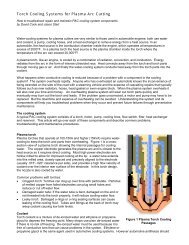
CLASSROOMTroubleshooting PAC Cooling Systems:Increase Uptimeand Parts Life byKeeping CoolWhat is Torch Coolant?Torch coolant is a working fluidcomposed of de-ionized water and asolute to depress the freezing point.Where there is no risk of freezing,many shops use plain de-ionizedwater. De-ionized water is usedbecause it is free of conductive ionsthat can contribute to deteriorationof the cooling lines and hard startingof the plasma torch. Figure 2 is adiagram of the internal coolant passagesin a plasma torch. Thecoolant is similar to the agents usedin an automotive cooling systemwith an important distinction: radiatorantifreeze has materials to clogup leaks. These are not suitable forplasma systems.The Cooling SystemA typical PAC cooling system consistsof a motor, pump, cooling lines,torch, flow switch, heat exchangerand reservoir (see Figure 1).Motors 1 ⁄3 to 1 ⁄2 hp are standard.Usually the service of a motor islong unless there are constrictionsin the system causing the motor andpump to work harder.Pumps. Rotary vane pumps aretypically used in plasma systems.These have an adjustable bypassscrew that increases or decreasesthe operating pressure and flow ofthe pump. Bearings in these pumpswear out. The coupling betweenmotor and pumpcan break. Thevanes inside thepump can becomeworn downuntil the pumpwill no longerdevelop pressure.MotorCoolantReservoirCooling Lines. Cooling linescarry coolant to and from the plasmatorch. These usually contain themain DC power cables as well.Water-cooled power cables preventthe multi-stranded copper wire fromoverheating. In mechanized applications,cooling lines are usuallyrouted through flexible power trackor festooned above the cuttingmachine. They are subject to leaksfrom cracked or cut hoses, meltedholes, damaged connectors, etc.Constructions are also common,particularly in the return hose fromthe plasma torch. Debris from partsfailures may accumulate in the torchor in the return lead, restricting flow.The copper power cables can alsobreak down from constant flexingallowing filaments of copper to clogup the ends of the hoses. Constrictionsin the leads cause reducedflow and increased wear on thepump and motor.Torch. The torch is usually themajor constriction in any PAC coolingsystem. The internal water passagesare small in order to increasethe velocity of the coolant and maximizeheat exchange. Most high ampelectrodes are hollow-milled on theinside to create a post of copperaround the emitting element. Awater tube in a torch extends overthis post and forces coolant alongthe post and against the back wall ofFigure 1. Typical Torch Cooling SystemRotary-vanepumpFilterFlowswitchHeatExchangePlasmaTorch26Welding Design and Fabrication ■ November 2000
Figure 2the electrode to remove the heat(see Figure 2). It is critical that thetorch and coolant remain free ofcontamination to allow proper flowthrough these passages.Flow Switches. Flow switches aredesigned to prevent catastrophic failureof the torch and parts in the eventof low coolant flow. Brass blockplunger type devices are typicallyused with a microswitch that must besatisfied for the system to run. Flowswitches fail mechanically or electrically:either the plunger can stick orthe switch components can fail.Filters. Most systems use a particularfilter similar to most commerciallyavailable water treatment filters.Five-micron paper filters or deionizingfilters are standard. Theseshould be changed every fewmonths or whenever a drop in flowor pressure occurs.Heat Exchangers. Most systemsuse some type of heat exchangerwith radiator fins and fan to removeheat from the working fluid. Somesystems acutally chill the coolantusing a refrigeration unit. The mostcommon failure in these simplesystems is fan motor burnout.Coolant Reservoirs. These aretypically equipped with a level indicatoror float switch. The tank shouldbe checked daily to make sure thereis adequate coolant. Low coolantlevels can cause air to be introducedinto the coolant stream, whichreduces cooling. If the system isinterlocked, low coolant may causeintermittent or total shut down of thesystem. Particulate may accumulatein the bottom of the tank. Thisshould be flushed out and removed.Usually the returning flow of coolantcan be seen through the filler cap ofthe coolant reservoir.TroubleshootingChecking the coolant stream: Ifthe coolant pressure or flow appearsto fluctuate, check the coolantstream as it enters the top of thereservoir–it should be clear. If itappears milky white then air is probablygetting into the system–usuallybecause of a low level in the reservoir.Add coolant over a two-minuteperiod, while the pump is running, tokeep the coolant at the recommendedlevel. If this does not correct themilky white conditions there may bea loose connection on the inlet sideof the pump that allows air to aspirateinto the system. A commonproblem with rotary vane pumps isthat the acorn nut and sealing gasketare sometimes left off after anadjustment is made to the outputpressure. The acorn nut and gasketmust be in place to prevent air fromentering the system.Checking the coolant path: If thepressure or flow readings are belowthe manufacturer’s recommendationthe complete coolant path must bechecked. First, check the filter locatedjust before the pump. Next,check the pump itself. Over timepumps will have to be adjusted tocompensate for wear. Adjustmentprocedures vary with the type ofpump and should be detailed in theinstruction manual. Finally, inspectall hoses, leads and fittings toensure everything is properly tightenedand there are not any kinkedor broken hoses.Checking the coolant flowrate–“the bucket test”: To verify theactual flow through the system,perform this simple test. Remove thecoolant return lead from the reservoir.Start the pump. Collect thereturning flow of coolant in a cleancontainer for a determined period oftime (usually 1 ⁄2 to 1 minute), then shutoff the pump. Measure the volumeand convert this to gallons/ liters perminute/hour. Compare the findings tothe manufacturer’s recommendation.Checking Coolant flow rate–flowmeter: An even better way to ensureproper coolant flow is to install awater flow meter just before thereturn line to the coolant reservoir.A simple 0-4 gpm flow tube (under$50) works well. This is cheap insuranceagainst parts or torch failure.Check coolant conductivity/resistivity: Over time coolant canbegin to ionize and/or become contaminatedwith copper particulate orother conductive material. This cancause hard starting of the plasmatorch because of the high voltageelectricity used to initiate a pilot arccan be dissipated through the coolingwater. A conductivity meter canbe used to check the coolant.Coolant resistivity should be lessthan1 0 microOhms or greater than10,000 Ohms/cm resistance.November 2000 ■ Welding Design and Fabrication27
CLASSROOMDon’t Cut Your ProfitsWith PlasmaA productive and efficient mechanizedplasma-arc-cutting operation canmake the difference between profitsand losses on a metal-fabricating job. Ahighly skilled operator produces morecut pieces, of higher quality, with lessscrap material and less rework downthe line. He saves money on torchesand consumables by using them correctly,and minimizes machine downtimethrough simple preventive measures.Here we discuss 10 commonmistakes that companies make in theirplasma-cutting operations, and how toavoid each of them.1. Using consumable parts untilthey blow. Look in your used-partsbucket and you will probably see partsthat have been run to failure. Usingseverely worn consumables can notonly ruin a good piece of metal, it cancause expensive torch failures andunnecessary downtime. The experiencedoperator can often tell by soundor arc color, or by subtle changes intorch height, when parts have worn.The best way to judge the condition oftorch parts is to periodically check thecut-edge quality and check torch partswhen the cut begins to deteriorate.Keep a record of the average parts lifeover time (in number of starts or arcontime) and develop guidelines forexpected parts life based on the amperage,material, and thickness.Once average parts life is establishedthe operator will know when to checkand replace the parts, preventing afailure.2. Changing consumable partstoo frequently. Look in your usedpartsbucket and you may also findparts that are still usable. It is a commonand expensive practice tochange-out consumables too frequently.When an operator changesthe parts, he needs to know what tolook for. If a nozzle is gouged or if thehole is worn out-of-round it should bereplaced. To tell if an electrode isspent, check the pit in the electrode element—theelement is the silver-coloredinsert held in the copper:hafnium for air and O2, tungsten for N2or Ar-H2. Generally, the pit should notexceed 3 ⁄32 inch for air and O2 and 1 ⁄8inch for N2 or Ar-H2. Gas swirlersshould only be changed if a close examinationreveals dirt or grease in theholes, cracks, arc burns, or excessivewear. The same holds true for shields,which should only be replaced if theyshow signs of physical damage. Oftenshields can be cleaned of metal spatterand reused.3. Using the wrong parts and parametersfor the job. Consumableselection depends on the material andthickness being cut, the amperage andplasma gas used, and other parameters.The operator’s manual will definewhich consumables are appropriate forvarious types of cutting. Using incorrectconsumables can lead to shortenedparts life and reduced cut quality.It is particularly important to run partsat the correct amperage. The best cutquality and parts life is usually achievedwhen amperage is set to 95 percent ofthe nozzle rating. Insufficient amperagecauses sloppy cuts; excess amperageshortens nozzle life.4. Assembling the torch incorrectly.The torch should be assembledso that parts align correctly andfit together snugly. This ensures goodelectrical contact and the correct flowof gas and coolant. When changingparts, keep consumables on a cleanshop rag to prevent dirt or metal dustfrom contaminating the torch. Whenapplying o-ring lube, use just enoughto put a shine on the o-ring. Excesslubrication can cause clogging of thegas swirler and metal-dust contaminationin the torch. This can lead to28Welding Design and Fabrication ■ November 2000
uncontrolled arcing in the plasmachamber and, ultimately, torch failure.Grease should never be applied tothe torches—it can cause destructivearcing and burning within the torch.5. Neglecting routine torch maintenance.Torch threads must be keptclean and seating areas should bechecked for contamination or mechanicaldamage. Clean any dirt,metal dust, or excess o-ring lubricantout of the torch using a cotton swaband electrical contact cleaner or hydrogenperoxide.6. Not checking gas and coolantflow. Check the flow and pressure ofgas and coolant every day. If flow is insufficient,consumables will not coolproperly and parts life will be reduced.Inadequate flow of cooling water, due toworn pumps, clogged filters, lowcoolant level, etc... can cause parts andtorch failure. Constant gas pressure isimportant to maintaining the cutting arc.Excess gas pressure is a commoncause of hard starting, and can alsocause rapid deterioration of electrodes.Likewise, plasma gas must be keptclean to prevent short consumable andtorch life. Compressed-air systems areespecially prone to oil, moisture, andparticulate contamination.7. Piercing too low. Even slightvariations in torch height can affect theangularity of the cut surface. Torchheight during piercing is particularlyimportant. One common error is topierce too low. This causes moltenmetal to spatter the front of the nozzleand shield. Arc snuffing can occur ifthe torch pierces when touching themetal, or drags along the surface whilecutting. If the arc is snuffed, the electrode,nozzle, gas swirler, and sometimesthe torch are destroyed. Piercingat a height of 1.5-2 times the recommendedcut height protects the torchand parts.8. Cutting too fast or slow. Cuttoo slow and cut pieces will developlow-speed dross—a large, bubbly accumulationof dross along the bottomedge. Slow speeds may also cause awidening of the kerf and excessiveamounts of top spatter. Cut too fastand the arc will lag backwards in thekerf, causing a beveled edge, narrowkerf, and a small, hard bead of drossalong the bottom edge of the cutpiece, that is difficult to remove.9. Stretching the arc. Arc stretchingcan occur at the beginning and endof the cut if the arc has to stretch, orThe torch should beassembled so that parts aligncorrectly and fit together snugly. Torchthreads must be kept clean andseating areas should be checked forcontamination or mechanical damage.deviate from a straight, perpendicularpath, to find metal. Arc stretching cancause the arc to cut into the side wall ofthe nozzle. When performing an edgestart, the plasma arc should be startedwith the nozzle orifice centered directlyover the edge of the workpiece. This isimportant to remember in punchpress-plasma operations where thearc is started from a punched hole. Inthis application, the arc should bestarted off the edge, not the center ofthe punched hole. Arc stretching canalso occur at the end of the cut if thetorch is programmed to run off theplate with the arc on, or if the lead-outfollows the kerf of previously cut metal.Timing of the arc-off signal and programmingof the lead-out can minimizethis effect.10. Crashing the torch. Torch collisionswith the workpiece can be preventedby programming the shape-cuttingmachine to travel around, ratherthan over, cut parts. Torch-height sensorsalso offer protection from torchcrashes by correcting for variations inthe material. However, voltage-regulatedheight controls can fail to protectthe torch. For example, torch diving oftenoccurs at the end of a cut if the torchfollows the kerf for too long. The torchheightcontrol dives to compensate forincreased voltage as the arc stretches.Careful programming of the lead-outand torch-height control function canminimize this. Finally, breakawaytorch-mounting devices can help preventdamage to the torch if a collisiondoes occur.November 2000 ■ Welding Design and Fabrication29
CLASSROOMWritten By: David J. Cook, Kirk Ferland,and Jason StartFigure 2NewConditionElectrode wear inair, oxygen plasmaHow to tell good electrode wear from badto improve system performanceElectrodes for high-powered plasmacutting systems are highly engineered,consumable parts, similar in design,material, and function to an automotivespark plug. Like spark plugs, electrodesemit high-voltage electricity in ahigh-temperature environment.The materials in electrodes must withstandthe temperatures of plasma arcemissions; endure swirling, high-velocitygas jets; and provide an airtight seal forhigh-pressure gases and fluids. Theelectrode, like a spark plug, is the hardest-workingcomponent in the system.A good mechanic can tell a lot aboutthe health of a combustion engine bylooking at the spark plugs. A trainedplasma technician can do the same fora plasma system by learning how to inspectthe electrode, understanding normalwear patterns, and knowing how tospot signs of trouble.The electrode carries DC power fromthe plasma power supply to the metalplate. Typically, it comprises a copperor copper-silver composite holder thatcontains an emissive element of hafnium—ahigh-melting-point metal thatcan sustain an arc in air and oxygencutting environments. The emitting elementis eroded away slowly by the heatof the arc and the high-velocity plasmagas stream. Most of this wear occurs atthe start and stop of a cut, when themolten hafnium material quickly heatsup and cools down, melting and thenresolidifying.During normal wear, a small, concavepit forms in the end of the part thatwears away steadily, a few thousandthsof an inch at a time, to a depth of 0.040to 0.125 inch, depending on the torchand consumable design and materials(see Figure 1).When the pit becomes too deep, thearc attaches to the holder material andmelts it. The electrode fails when it nolonger initiates and sustains an arc. Ifmolten material from the electrode isdeposited downstream into the bore ofthe nozzle, it causes a blowout—catastrophicfailure of both the electrodeand nozzle.Normal electrode life for oxygen plasmasystems is one to two hours of arcontime and 200 to 300 pierces. Air systemstypically can achieve twice thislife, 400 to 600 starts, because the nitrogencomponent of air makes it lessreactive with the electrode. Oxygenplasma systems with inert start gasesand current ramping can reach 1,000 ormore starts before an electrode changeis necessary.Plasma Arc Cutting Copper Copper-Silver(PAC) System Electrodes CompositesInches of WearInches of WearHigh Precision(Oxygen Plasma)0.030 - 0.050 0.060 - 0.080Water Injection(Oxygen Plasma)0.040 - 0.080 0.100 - 0.140Conventional Dual Gas(Oxygen Plasma)0.040 - 0.080 0.100 - 0.140Conventional Dual Gas(Air Plasma)0.090 - 0.120 0.100 - 0.140Figure 1During normal wear, a few thousandths of an inch of an electrode wearsaway each time it’s used, depending on the torch, consumable design, andmaterials.Figure 3Normal WearFigure 4Normal WearHalf-lifeFigure 5Off-center BurnElectrode ExamplesKnowing the difference betweengood and bad electrode wear can helpyou improve your system’s performance.New Condition. Figure 2 shows apicture of a new electrode. This electrodeis a welded copper-silver compositewith silver on the front andcopper on the back.Normal Wear. Figure 3 shows anelectrode with a normal wear pattern.The hafnium pit is well-centered anduniform in shape, indicating good alignmentof consumables and a properplasma gas swirl. The depth of the pit isapproximately 0.100 in. The front edgesof the electrode are sharp and distinct,and the silver has no severe discoloration.Some grayish-colored oxides30Practical Welding Today ■ May/June 2002
Figure 6Moisture on StartFigure 7Coolant LeakFigure 8Low PreflowFigure 9BlowoutFigure 10Low PlasmaGas (Snuffing)Figure 11High Gas Flowon the front surface of the part arenormal.Normal Wear Half-life. The electrodein Figure 4 shows a normal wearpattern that has been pulled prematurelyfor another reason, such as thetorch riding the plate; torch crash; voltagechange (when the voltage rises asthe distance between the torch tip andplate increases); or a change in cutquality, such as slagging or excessivebeveling. The pit depth is 0.078 in.Although this part looks consumed, itmay burn another 100 starts or moreand proceed to a depth of 0.100 or0.140 in. before approaching failure.Off-center Burn. Figure 5 exhibitsan off-center burn. This problem can beeasy to spot. It usually indicates a severegas flow problem—such as a brokenor clogged swirl ring—or a torchpart misalignment caused by assemblyerrors or fit-up problems. If completelychanging torch parts doesn’t correctthe problem, the torch probably isdamaged.Moisture on Start. Figure 6 showsthat moisture was present during thearc start. This electrode has a roughswirling arc track from the wrench flats—the side of the part where the wrenchfits—down to the face of the electrode.Preflow gas moisture can cause thehigh frequency to attack the silvermaterial. The front edges of the silveraren’t sharp; instead, they’re smoothedover with a sandblasted surfacecondition.Check preflow gas for signs of moisture.One quick check is the papertowel test: Hold a clean paper towelunder the torch with gas flowingthrough the system (in the test or gascheck mode only). No sign of moistureor contamination should be present.Coolant Leak. As shown in Figure7, coolant leaks produce severe arcingof the electrode face and sides, characterizedby pitting and pocks in the electrodesurface. The front surface isrough and black with shiny meltedspots of holder material.This problem often is caused by cutO-rings, insufficient O-ring lubrication,or loose or misaligned parts. The papertowel test can detect a coolant leak, ascan a mirror, on which mist will form.Low Preflow. Figure 8 illustrateshow insufficient gas during arc initiationproduces a “lazy start”—the arc takestoo long to travel from the start point,usually a sharp corner like a wrenchflat, to the emitting element. Theseparts have a fairly uniform ring ofmolten holder material surrounding thepit. The surface may look like a soldersplash or weld puddle has formedalong the front of the part.Blowout. Figure 9 shows an electrodethat has been run to catastrophicfailure. Because the electrode is upstream,it will damage the nozzle whenmolten material is blown out of the endof the part and deposited into the nozzleinterior.Low Plasma Gas (Snuffing). Lowgas flow is indicated if the electrodehas small pockmarks all over its endand there is corresponding damage tothe interior of the nozzle (see Figure10). Low gas flow produces uncontrolledarcing between the nozzle andelectrode.Check the gas flow rates to the torch.The best way to do this is with a flowmeter(0 to 400 cubic feet per hour) anda hose placed on the outlet of the torchwith the system in test mode.If a flowmeter isn’t available, a quickcheck is to feel the gas flow at the outletof the torch with only plasma gasturned on. You should feel a swirlingflow of gas that actually has a suctionforce.High Gas Flow. If the nozzle is ingood condition but the electrode has adeep, concentric pit, the plasma gasflow rate may be too high (see Figure11). If the plasma gas swirl is too intense,the element erodes quickly. Thiscan cause a rapid, deep wear pattern.Check the volumetric flow rate of theplasma gas.Learning how to identify differenttypes of electrode wear can help youanticipate failure, save money on parts,and improve system performance.David Cook is technical servicesdirector, Kirk Ferland is technicalservice team leader, and JasonStart is field service technician of<strong>Centricut</strong> LLC, Two Technology Drive,West Lebanon, NH 03784, phone800-752-7623, fax 800-317-0438, e-mail djcook@centricut. com, Web sitewww.centricut.com. <strong>Centricut</strong> is amanufacturer of consumables forthermal cutting torches.Reprinted with permission from theMay/June 2002 issue of PracticalWelding Today ® , copyright 2002 byThe Croydon Group, Ltd., Rockford,Illinois, www.thefabricator.com.May/June 2002 ■ Practical Welding Today31
CLASSROOMWritten By: David J. Cook<strong>Centricut</strong> Technical Services DirectorWhat to know beforeselecting a manual plasmaunitUnderstanding size, power,components, costThe first plasma arc cutting (PAC)systems, developed in the ’60s,were 1,000-amp monsters designedto blast through 6-inch stainlesssteel. Their mechanized torcheswere moved by X-Y cuttingmachines and powered by DC unitsthe size of refrigerators. Surprisingly,the PAC industry evolved from hightolow-amp systems, water- to gascooled,and from gas- to air-cooled.Today’s hand-held air PAC systemsare lightweight, portable, andrelatively powerful for their size.They are used for cutting everythingfrom thin-gauge metals to 1-inchplate. More traditional console PACsystems also are available to handlecutting tasks up to 2 inches andmore. Hand-held PAC systems arenow the fastest-growing segment ofthe PAC market because they offer afast, efficient, and affordable way tocut.This article offers an overview ofmanual PAC technology from theearly days to the present, includingan explanation of different powersupplies, recommendations forselecting and sizing a system, andother functions and features to lookfor in a hand-held system.Regardless of the size, all PACsystems contain the same basiccomponents, including a gas supply,DC power supply, and plasma torch.The torch requires a circuit to initiatean arc and a cooling system.Gas SupplyMost older plasma systems usednitrogen as the plasma gas and airor CO 2 as the secondary gas, whichrequired expensive bottles or bulkcontainers. Now, most hand-heldsystems use clean, dry shop air tocool the torch and provide thenecessary plasma gas.Shop air currently is the most affordableand versatile plasma gas. Itis readily available and providesgood cut edge quality on mild andstainless steel and aluminum. Withthe exception of special applications,such as thick stainless steeland aluminum cutting or plasmagouging, almost all hand-held systemstoday use air plasma. Severalmanufacturers even have developedair plasma systems with small,onboard air compressors.Power SuppliesPAC power supplies are direct currentelectrode negative (DCEN).The process requires a constantsource of DC and a high open circuitvoltage (OCV) to initiate the arc(typically at least twice the operatingvoltage). The following is a summaryof some basic differences amongPAC power supply types.DC Droopers. Early plasma systemsincluded “drooper” powersupplies, named for their droopingoutput power curves. These unitsprovided a high OCV and relativelystable current and operating voltage.32Practical Welding Today ■ July/August 2000
Metal Minimum Recommended ApproximateThickness System Size Cutting Speed*18 ga. 12 amps 35-100 IPM1⁄8 in. 12 amps 10-20 IPM1⁄4 in. 25 amps 15-20 IPM3⁄8 in. 40 amps 25-35 IPM1⁄2 in. 55 amps 25-40 IPM3⁄4 in. 80 amps 10-25 IPM1 in. 100 amps 10-15 IPM*Ranges shown are based on claims of several manufacturers. Speeds are based on carbonsteel cutting. Actual cutting speeds vary, depending on torch and power supply design.Figure 1 Material thickness determines the system size.They used a fixed-output DC rectifierbridge consisting of a series ofdiodes to convert AC power from atransformer into usable DC for thecutting process.These simple systems created alot of power but wasted energy andhad too much “ripple” in their outputpower. (Ripple is fluctuations in DCoutput that cause a rough cut andshort part life.) To further regulatepower output, multiple transformerscould be used, each providing ahigher level of output current.Reactors. Reactor power supplieswere the next step in powerregulation. These used a reactordevice to control the amount of ACvoltage supplied to the bridge rectifier.The reactor consisted of a groupof AC coils with a DC windingaround it. The current in the DCwinding controlled the amount of ACthat passed through the reactor,which created an adjustable transformerthat allowed variable DC outputfrom the bridge.SCRs. Silicon-controlled rectifiers(SCRs) are another type of continuouslyvariable output power supply.SCRs convert three-phase ACpower from a transformer directly toDC. They require huge capacitorbanks and large transformers. SCRsare large and powerful and are usedfor high-amp PAC systems but arenot well-suited to hand-held applications.Switch-mode. Switch-modepower supplies use transistors tomodulate DC power after the rectifier.Choppers are a type of switchmodepower supply that use powersemiconductor devices such as isolatedgate bipolar transistors(IGBTs) —which take raw DC withripple and chop it up, rapidly switchingthe power on and off to smooththe output characteristics. IGBTscan be fired much faster than oldreactor-type power supplies. Theresult is a very smooth output powercurve.Inverters are another type ofswitch-mode power supply. They usedevices such as transistors on theinput side of the power train to raisethe frequency of the AC into theContinuedCutting Speed (IPM)2001801601401201008060Metal Thickness vs. Cutting SpeedTypical 35-amp PAC SystemSpeed too fastfor hand cutting;too much powerfor materialthicknessOptimum speed rangefor production cuttingrecommended capacitySpeed too slow;not enough powerfor materialthickness402000 1/ 8 1/ 4 3/ 8 1/ 2 5/ 83/ 4Metal Thickness (Inches)Figure 2If the system doesn’t have a recommended capacity rating, an analysis canbe made by referencing the cut charts or a cut speed curve.July/August 2000 ■ Practical Welding Today33
CLASSROOMWhat to know Continuedtransformer. Higher frequency inputallows a much smaller transformer tobe used. Because a smaller transformeris used, inverters are muchlighter and more portable than conventionalpower supplies, makingthem ideal for hand-held applications.Early inverter power supplieswere limited by low output currentand complicated design and poorreliability. When problems occurred,sophisticated techniques and troubleshootingwere required to solvethem.Today’s inverters are more reliable,robust, and powerful. Mostmanual PAC systems now useinverter or switch-mode technology.These sophisticated, electronicallyor microprocessor-controlled devicesare better able to tolerate variationsin line voltage, take more abuse inthe field, and deliver better cuttingperformance while consuming lesspower.TorchesAll plasma torches contain thesame basic elements, including:1. an electrode to carry the negativecharge from the power supply.2. a gas distributor, or swirl ring, tospin the plasma gas into a stable,swirling vortex.3. a nozzle to constrict and focusthe plasma jet.The torch is primarily a holder forthe consumable parts. Torchimprovements have been aimed atoptimizing the torch and consumabledesigns to improve cooling,enhance starting characteristics,and increase cutting capacity.Improvements also have been madein material selection for consumablesand torches to improve durability,such as using high-temperaturedurable plastics in place ofceramics.Ergonomics have improved withfeatures such as trigger torches,better handle designs, and optionsfor torch angle or adjustable torchheads. Safety improvements includeparts-in-place (PIP) circuits andswitches or triggers to prevent thetorch from firing without the partsproperly installed and the operatorready.Most hand-held systems on themarket today use one of two methodsto initiate the plasma arc. The triedand-truemethod is a high-frequency(HF) starting circuit built into thepower supply. This system uses ahigh-voltage transformer (similar to abug zapper), capacitors, and sparkgapassembly to generate a highvoltagespark at the torch.The spark ionizes the plasma gas,enabling current to flow across theair gap between the nozzle andelectrode. The resulting arc is calledthe pilot arc. High-frequency startingsystems are simple, relativelydependable, and require no movingparts in the torch. However, they doneed periodic maintenance to preventhard-starting problems.Another potential problem is thathigh frequency radiates from thesystem, creating electrical noise thatmay interfere with sensitive electronicequipment.Contact start torches use a movingelectrode or nozzle to create theinitial spark that enables the pilot arc.When the torch is fired, the electrodeand nozzle are in contact in a “deadshort,” or short circuit. But as the gasenters the plasma chamber, it blowsthe electrode back (or the nozzle forward),creating a spark. This processis similar to the spark created whena household electrical plug is pulledquickly from a receptacle.Contact start torches producemuch less electrical noise than HFsystems. These also are “instant-on”torches, which reduce cycle timebecause of the lack of preflow.Sizing a SystemThe machine should have sufficientpower to handle typical cuttingtasks with ease, and it should beable to cut the material at about 20inches per minute (IPM) or faster.When an operator becomes accustomedto the speed of PAC, it is possibleto hold the line profiling at 70 to80 IPM. Even faster speeds are possiblewith template cutting or cuttingaccessories such as circle cuttersand rolling plate followers.Before purchasing a system, thethree material considerations are:•Types of materials to be cut• Thickest and thinnest materialsto be cut• Most commonly cut materialthickness34Practical Welding Today ■ July/August 2000
The third consideration is themost important when selecting aplasma system. Often, errors aremade in sizing a system for anapplication, and too little or toomuch power is acquired for the mostcommon cutting task.Underpowering, or trying to cutat the high end or over the system’scutting capacity, will lead to poor cutquality, low cut speeds, and hightorch and part consumption.Overpowering can lead to cut qualityproblems, such as heat distortion,wide kerf, and low-speed dross.Generally, more power is better,especially because most systemsnow allow variable output so that thepower can be dialed down for thinnermaterials. Figure 1 includessome basic cutting capabilities for arange of different amperages.Equipment manufacturers rate thecutting power of a PAC system witha thickness or capacity rating. Theseratings are based on carbon steeland list the thickest metal that thesystem will cut with reasonablespeed and cut quality, from an edgestart. In an edge start, the operatorfires the torch with the nozzle justover the edge of the plate, then beginscutting.For a pierce start, the operatorfires the torch over the plate andblows a hole through the materialbefore cutting. Piercing throughmaterial requires more power andoperator skill than edge starting. Forthese reasons, the pierce rating, orpiercing capacity, usually is half thecutting capacity. For example, most100-amp systems will cut 1-inchplate from an edge start, but thethickest they will pierce is 1 ⁄2-inchplate.Some manufacturers also offer arecommended capacity, which is amore useful specification than maximumcapacity. The recommendedcapacity is the optimum thicknessfor the machine in terms of quality,parts life, cut speed, duty cycle, overallproductivity, and cost of operation.If the system doesn’t have a recommendedcapacity rating, ananalysis can be made by referencingthe cut charts or a cut speedcurve (see Figure 2). The regularlycut material should fall somewherein the middle of the cut chart, andthe corresponding speed should beat least 20 IPM.Cost of OperationMany variables contribute to theoverall cost of operation for PAC,including labor, power, duty cycle,gas, shop air maintenance, consumables,consumables life, speed ofcut, amount of cleanup, or secondaryoperations required.The two most important factors toconsider when purchasing newequipment are consumable cost andconsumable life. Because the part lifeof different systems varies, consumablecost alone is not the best measureof a system’s cost of operation.Consumable cost, or the totalconsumable cost divided by the consumablelife in hours of arc-on timeper hour, is the most useful measurement.For example, if the cost ofa nozzle is $4, the cost of the electrodeis $6, and together a set lasts2.5 arc hours, then the cost perhour, or CPH, is ($4 + $6)/2.5 = $4.Just the nozzle and electrode areused for this calculation because theother consumable parts aredesigned to last much longer. To calculateCPH for all torch components,a weighted average shouldbe used based on usage ratios.Typically, shields, swirl rings, andcaps outlast nozzles and electrodesin a minimum 20-to-1 ratio.Before purchasing a new handheldsystem, a company should doits homework by:• Knowing what kind of powersupply technology is used andunderstanding the system’s capacity.• Not skimping on power by purchasingenough power to do the jobwith ease.• Calculating the cost of operation.• Looking for an ergonomic andsafe torch design.•Testing the sales claims with areal-world cut test.• Making sure the system isbacked up by a good warranty.• Adding technical support afterthe warranty expires.David Cook is the TechnicalServices Director with <strong>Centricut</strong>,LLC, 2 Technology Drive, WestLebanon, New Hampshire 03784,phone 800-752-7623,fax 800-317-0438, e-mail djcook@centricut.com, Web site www.centricut.com.<strong>Centricut</strong>, Inc., is amanufacturer of consumables andtorches for thermal cuttingmachines.Reprinted with permission from theJuly/August issue of PracticalWelding Today ® , copyright 2000 byThe Croydon Group, Ltd., Rockford,Illinois, www.thefabricator.com.July/August 2000 ■ Practical Welding Today35
CLASSROOMWritten By: David J. Cook<strong>Centricut</strong> Technical Services DirectorCNCs form mechanizedshapeWhat you need to know before you buy your next controlThe computer numerical control, orCNC, is the most critical component ina mechanized shape cutting system.This article provides an overview ofCNC technology, including the functionof the CNC in a motion controlsystem, a short history of CNCs formechanized shape cutting, commoncontrol features, and a glimpse at thefuture of CNCs and related motioncontrol technology. A basic understandingof the technology will preparefabricators to spec out a controlthat meets the needs of their cuttingoperation as well as their financialrequirements.Motion Control SystemsA motion control system convertsinput commands into mechanical motion.Figure 1 shows the four maincomponents of a typical motion controlsystem:1. CNC2. Driver3. Mechanical tool positioner4. Feedback devicesThe CNC is the “brain” of the motioncontrol system. It controls thehuman machine interface (HMI),where the machine operator entersinput commands. It processes theinput commands into output signalsthat will actuate the driver andresponds to feedback loops to trackposition and speed correctly.CNCs for mechanized shape cuttersusually consist of a processor,some amount of internal memory, akeypad, an alphanumeric displayscreen, and a communications link.The operator loads CAD-generatedpart programs into the control eitherby disk or by downloading from ahost computer. The CNC generates apath profile by making a series of calculationsor cutting algorithms andthen sends the path profile commandsto the driver.The driver provides the “muscle” ina motion control system. It translatescommands from the “brain” (theCNC) into physical motion. In ashape cutting system, the driver is adrive amplifier/motor combination.Pulse width modulation (PWM) DCservomotors typically are used onshape cutters because of their highefficiency and response.The mechanical tool positioner isthe shape cutting machine. It acts as“bones” that support the movement ofthe system. Figure 2 shows a typicalgantry-style cutting machine. Rack-36The Fabricator ■ February 2000
and-pinion drives are the most commonlyused method of motion transmission.Bearings support the moving elementsof the machine in the X, orlongitudinal (the bridge moving alongthe rails), and Y, or transverse (thecarriage moving along the bridge),axes. The cutting tool moves up anddown in the Z axis.This function oftenis controlled by a separate motioncontrol system—the automatic torchheight control.The feedback devices are sensorsused to relay information back tothe control. Shape cutters usually useencoders and tachometers for feedbackloops. Encoders track the cuttingtool’s position. Tachometersmeasure velocity and acceleration.Figure 3 shows a typical velocity andposition loop.Most current systems close the positionand velocity loop. This meansthat the position and speed of the cuttingtool are monitored constantly andrelayed back to the CNC. The CNCcompares actual speed and positionwith commanded speed and position,making constant adjustments to keepthe cutter on path and at the correctspeed. The faster this information isupdated and exchanged, the moreaccurate the cut path will be.Original TechnologyIn the 1970s and early ’80s, severalcompanies introduced programmablegeneral-purpose automationtools. These early CNCs were fairlyprimitive devices with little programmability.They were based on microcontrollertechnology and used eightbitmicroprocessors with peripheraldevices such as serial ports, chip selectcircuits, and parallel ports.Later on, these controls were upgradedto 16-bit microprocessors. After16 bit came the 32-bit digital signalprocessor (DSP). Each of thesenew processors doubled the speed ofthe operating system.Still, all of these systems used embeddedCNC microcontrollers andthus relied on EPROMs (electricallyprogrammable read only memory),which were physical chips that containedthe software. The programminglanguage was machine code orassembly language. Any change tothe software in the EPROM necessitatedinstallation of a new chip.In the mid-’80s, the personal computerbecame the predominant technologyused in development stations.With the PC came motion controlcards (MCCs). This meant that theoperator could use a PC for the “frontend”—the HMI, including the keypad,screen, joystick, etc.— and offloadthe motion control algorithms to theMCC. The feedback loops, such asvelocity and position, also were controlledby the MCC.This led to a dramatic change inCNC technology. Computer chipmakersmade continuous improvementsto their processors to increase computationspeed. With faster processingspeeds, bigger hard drives,and more memory to work with, CNCmanufacturers were able to add morefunctions and features to the controls.New TechnologyMost CNC manufacturers now usePC-based controls in one form oranother. They use DOS-based, Windows® , or Windows NT platforms,bringing the power of Microsoft andIntel ® to the cutting machine. Theseeconomies of scale keep the pricesof off-the-shelf computer componentparts affordable.In addition to handling the HMI,PCs now can use a graphical user interface(GUI). Graphics make theCNC more intuitive and easy to use.The higher-level programming languagessuch as C++ are more powerfuland allow CNC manufacturersto acquire the engineering resourcesto develop better products.CNC original equipment manufacturers(OEMs) are divided intotwo schools that are as much philosophicalas technical. One groupuses the PC platform to handle theHMI and offloads the motion controlalgorithms and feedback loops to anMCC or DSP. This method of distributedprocessing allows additionalMCCs to be added without slowingdown the user interface. It is also astable platform. However, as much as30 percent of the processing speed iswasted on communications betweenthe processor and the MCC.The other group of CNC developersuses the PC to control all functions;one processor handles all theHMI, path profiles, cutting algorithms,position and velocity loops, and filestorage. This approach can result inincreased speed and tight coupling ofthe output commands and the feedbackloops. It also limits the hardwarenecessary and allows changes andupdates to be added through software.However,adding more devicesto be controlled theoretically couldslow down the processing speed,causing the graphics and user interfaceto slow down as well.ContinuedFebruary 2000 ■ The Fabricator37
Functions and FeaturesHere is a list of functions and featuresto consider when purchasing anew CNC.1. Ease of use. Many CNCs areintuitive and as easy to use as a Windows-basedprogram. Features suchas good graphics, clear and brightscreens, touchscreens or tactile -CLASSROOMCNC form mechanizedshape Continuedsoftkeys, and online help screenshelp to make the CNC easier to useand may reduce expensive trainingtime and errors.These features aren’tjust bells and whistles—they help toreduce operator training time andexpensive errors.2. Processing speed. The speedof the CNC’s processor is important.Figure 1This motion control system flow chart shows how input commandsare converted to mechanical motion.Figure 2This is a typical gantry-style cutting machine. Bearings supportthe moving elements of the machine.Figure 3By using a system with velocity and position loop, the positionand speed of the cutting tool are monitored and relayed backto the CNC.38The Fabricator ■ February 2000
PC-based controls now offer speedsup to 266 megahertz. It is possible(but not necessary yet) to use the600-megahertz Pentium ® chip in aPC-based control. Faster processingspeed means faster download timesfor large nests of parts, faster kerfcompensation, and better resolutionon feedback devices. However, thereis a point of diminishing returns inwhich the added performance doesnot justify the cost.3. Accuracy. Closed-position andvelocity loops help to maintainsmooth motion and accuracy in thepath profile throughout the range ofpossible velocities. Real-time motiondisplays allow the operator to verifyvisually that the cut path is accurate.4. Communications. Speed ofcommunications is important. If partprograms are downloaded from ahost computer, a fast modem is helpful.Serial ports with 115 to 230Kbaud rates are available.5. Noise suppression. Sensitivecomponents in the CNC must be isolatedfrom electrical noise or electromagneticinterference (EMI) that radiatesfrom plasma cutters, weldingequipment, and other sources. Theinput and output ports to the CNCshould be protected by adequateshielding and/or optical-isolationports.6. Data management. CNCs needsufficient hard drive space to storecommonly used data files.This speedsupload times and simplifies operation.One- to three-gigabyte hard drives areavailable from several manufacturers.This hard disk space also can be usedto store online help files, digital cutcharts, parts life records, and inventorycontrol systems.7. Open architecture. Open architecturemeans that the CNC is builtwith industry-standard software andhardware components, which reducesthe manufacturer’s costs and, in turn,lowers the end user’s initial capitalcost. Replacement parts for openarchitecture CNCs also are significantlylower than proprietary components.If a part in the control such asthe CRT or a disk drive breaks, replacementsare readily available fromcomputer parts suppliers.8. Technical support. Despite thesales claims, no product is perfect.Technical support always is required.CNC manufacturers should back uptheir products with service, whichmeans fast turnaround on factoryrepairs, access to well-trained techniciansand engineers, and a strongcommitment to customer satisfaction.Future TechnologySeveral manufacturers are workingon ways to collapse some of the distributedprocesses used on cuttingmachines. This could eliminate a lotof duplicated hardware and softwareeffort, lowering the system’s cost andmaking it easier to use.For example, the automatic torchheight controls used in plasma arccutting usually have a separate motioncontrol system. This system canbe bundled into the CNC. Powersupplies and gas consoles for plasmasystems are also laden withduplicated automation hardwareand software that can be collapsedinto the CNC.The goal of new-product developmentwill be to provide more accuratepositioning, better cut quality,and, most of all, simplicity and easeof use. With a centralized system,the cutting machine can be fullyautomated and the cutting processreduced to just a few steps.The machine operator will loadthe plate and punch in the materialtype and thickness. The CNC willadjust all parameters for the cuttingprocess automatically and providethe operator with a digital cut chartshowing these parameters and therequired parts to be used in the cuttingdevice. When the operator hitsstart, the CNC will be in “autopilot”—all parameters will be adjusteddynamically to provide the best cutquality, parts life, and speed. Whenthe cutting operation is complete,the operator will unload a full nest ofnear-perfect cut pieces.ConclusionCNC technology has come a longway in the past 25 years. If you are afabricator shopping for a new shapecutting machine or upgrading an olderone for improved reliability andfunctionality, you will need to take aclose look at current CNCs.David Cook is the TechnicalServices Director for <strong>Centricut</strong> LLC,Two Technology Drive, WestLebanon, New Hampshire 03784,phone 800-752-7623,fax 800-317-0438,e-mail djcook@ centricut.com, Website www.centricut.com. <strong>Centricut</strong> is amanufacturer of consumables forthermal cutting torches.Reprinted with permission from theFebruary 2000 issue of TheFABRICATOR ® , copyright 2000 byThe Croydon Group, Ltd., Rockford,Illinois, www.thefabricator.com.February 2000 ■ The Fabricator 39
FOR COMPLETE INFORMATION ON OUR PLASMA, MIG, OXYFUEL, LASER AND VALUCUT CONSUMABLESCALL 1-800-752-7623, 1-603-298-7849 OR VISIT OUR WEB SITE AT WWW.CENTRICUT.COM1-800-752-7623 n 1-603-298-7849www.centricut.comTwo Technology Drive, West Lebanon, NH USA 03784© <strong>Centricut</strong>, LLC 2003