Standard Operating Procedure - Ultrafiltration - Department of ...
Standard Operating Procedure - Ultrafiltration - Department of ...
Standard Operating Procedure - Ultrafiltration - Department of ...
- No tags were found...

Create successful ePaper yourself
Turn your PDF publications into a flip-book with our unique Google optimized e-Paper software.
GEA Filtration Model L Pilot Plant<strong>Standard</strong> <strong>Operating</strong> <strong>Procedure</strong>s2-20101
TABLE OF CONTENTSPurpose………………………………………………..3Safety………………………………………………….4Storage & Waste Disposal…………………………...9System Description…………………………………..10System Operation Overview………………………...29Labstack Setup……………………………………….44Membrane Description………………………………48Supplemental Cleaning & Storage………………….562
Purpose and ScopeThis SOP covers the procedures for apparatus setup, startup, operation, andshutdown <strong>of</strong> the Model L’s M20 Lab Module (for flat sheet membranes) andSpiral Membrane Pressure Vessel (SMPV) in addition to documentation onmembrane materials.3
SECTION 1 – SAFETY4
Personnel ProtectionSafety glasses are required when operating this equipment and at all times whenworking in the laboratory.It is advisable to wear a lab coat when operating this equipment.Prior to operating this equipment all students must check in with the labmanager, pass a safety quiz and sign the safety log provided by the labmanager.Proper training and supervision are necessary to avoid injury or death <strong>of</strong>personnel working in any capacity around equipment, which is operating at highpressure, temperature, or vacuum.General Safety <strong>Procedure</strong>sProcess plants incorporate a combination <strong>of</strong> components, for example: rotatingmachinery, various electrical devices, ductwork for transporting gas under lowand high temperature vacuum and pressure, as well as various liquid piping.Each <strong>of</strong> these areas must be treated with respect to avoid personal injury ordeath as well as damage to the equipment. Always read and follow warningsigns and labels.Before operating any component, such as a fan, valve, heater, pump etc.,thoroughly review and understand the vendor’s instructions available in the plantmanual. Finally, when in doubt, ASK!Electrical SafetyGeneral:All power distribution equipment, control panels, and instruments containhazardous voltage, which can kill or maim personnel. Proper operation andmaintenance significantly reduce the degree <strong>of</strong> hazard. Only a qualifiedelectrician should be permitted to service and maintain electrical components.Routine observations should be used to look for signs <strong>of</strong> electrical problems.Unusually hot surfaces or burnt smells should be investigated promptly and thecause corrected by a qualified electrician.5
High Pressure EquipmentPressure vessels are liable to fail if the pressure exceeds the maximum allowableworking pressure. Major contributors for failure include but are not limited tosudden changes in the operating conditions or blockage <strong>of</strong> the flow passagesdownstream. Such a failure may cause economic and personnel losses.Therefore, pressure-relieving devices are used to minimize the potential loss <strong>of</strong>human life and economic investments.This device can be either a safety relief valve or rupture disk. The pressure atwhich the valve opens or disk ruptures is set a little higher than the normaloperating pressure.The output line from the system pump is fitted with a pressure relief valve.Consult with lab manager regarding pressure release settings for thisvalve.Do not adjust the pressure relief valve.All <strong>of</strong> the clamps from the tank outlet to the feed pump inlet can be low pressurestyle (as it is not high pressure until after the discharge <strong>of</strong> the pump). The 3/4"Clamps with the hinge are rated above 2000psi at 70degrF. It is only the 1.5"clamps on the pressure gauges and the 3" clamps on the 2540 Spiral housingthat require the dual bolt high pressure clamp.Note: ceramics (Tami module) are run at low pressure.6
High Pressure ClampsATTENTIONSAFETY WARNINGREVERSE OSMOSIS CLAMPSBecause the reverse osmosis system employs operating pressures that arehigher than normally encountered in dairy processing equipment, it is VERYIMPORTANT that only the proper types <strong>of</strong> clamps are used. When servicing thesystem, be sure that the proper type <strong>of</strong> clamp is used in the proper location. DONOT substitute any other type <strong>of</strong> clamp than the ones shown below.HIGH PRESSURE BOLTED(13 MHP) (13MHHM)LOW PRESSURE HINGEDThe high pressure bolted clamp is suitable for any Tri-clamp application. It mustbe used in any lines and connections in the high pressure piping circuits <strong>of</strong> thereverse osmosis system. For these lines in the high pressure circuit, do not useany other type <strong>of</strong> clamp! These clamps are properly tightened when the twohalves <strong>of</strong> the clamp are butted together.The low pressure hinged clamp is suitable for low pressure applications in anysize. Do not use these types <strong>of</strong> clamps in high pressure circuits.7
Pump Safety NoticeIt is unsafe to operate a centrifugal pump when both the suction and dischargeports are closed <strong>of</strong>f by valves at the same time. Such circumstances can result inthe disintegration <strong>of</strong> the pump housing.This phenomenon is fully appreciated in the engineering pr<strong>of</strong>ession and stated inthe pump literature. When a pump operates with closed valves, nearly all themotor power output is converted to heat and the temperature <strong>of</strong> the trapped liquidwill continue to rise.As it does, the liquid will expand and additional pressure will be created as theliquid expands eventually to above the liquid boiling point. The temperature willeventually stabilize where heat losses from the pump housing equal the heatgenerated. However at this point the internal pressure may exceed that for whichthe pump was designed.8
Waste and Hazardous MaterialsStorage and Disposal <strong>of</strong> WasteAll waste materials must be stored in sealed nalgen waste containers. Thecontainers must be clearly labeled WASTE with the contents <strong>of</strong> each chemicalcomponent in mol % or volume % concentration written clearly on the container.The container must also be labeled with the group / experiment name and thedate. The labeled and sealed container must be placed in the waste collectionarea located in the south-east corner <strong>of</strong> senior lab. Any chemicals or materialsthat require temporary storage until the next lab period must also be labeled withthe contents <strong>of</strong> each chemical component in mol % or volume % concentrationwritten clearly on the container, do not label temporary storage container aswaste. If the material to be temporarily stored is flammable it MUST be stored inthe flammables cabinets located on the east wall <strong>of</strong> senior lab. If the chemicalsare not flammable and not hazardous they may be stored in sealed containersnext to the ulfiltration equipment, the containers must be properly labeled aspreviously described. Check with the lab manager before deciding on theprocedure for temporary storage <strong>of</strong> chemicals.9
SECTION 2 – SYSTEM DESCRIPTIONSYSTEM DESCRIPTION10
The typical work flow for operating the Model L is shown below in Figure 1. The user begins bydetermining what type <strong>of</strong> separation they will be conducting with the Model L and then selectingan appropriate membrane filter. Once the desired membrane has been selected, the user mustthen configure the Model L for the membrane selected.Follow these guidelines to determine filtration type and membrane:Determine either the size or molecular weight <strong>of</strong> the particle to be separatedIdentify which type <strong>of</strong> filtration (MF, UF, or RO) will be required to perform the desiredseparation.Review specifications from membrane manufacturers to identify appropriate membrane.Pay close attention to the following:<strong>Operating</strong> limits <strong>of</strong> candidate membranes (pH, temperature range, maximum pressure).The maximum pressure (Pmax) <strong>of</strong> the membrane will determine how concentrated <strong>of</strong> a solutionyou can filter. The Model L has a Pmax <strong>of</strong> 1000 psi.11
Flat sheet type membrane assembly in plate-and-frame module shownon the right.Spiral membrane shown on the left.12
Design BasisThe GEA Filtration Model L Pilot Plant is a small-scale system for testing variousmembrane filtration processes up to 1000 psig (70 bar). It is an excellentresearch/development tool for membrane filtration, namely reverse osmosis (RO),nan<strong>of</strong>iltration (NF), ultrafiltration (UF), and micr<strong>of</strong>iltration (MF).The base system incorporates the plate and frame Lab Module M20 with 7.8 sq ft. (0.72sqm) <strong>of</strong> membrane area. The Lab Module M20 accepts flat sheet polymericmembranes <strong>of</strong> all types. It has the unique feature <strong>of</strong> being able to simultaneouslyscreen a number <strong>of</strong> flat sheet membranes. The Lab 20 module can accept as fewas 4 flat sheets to as many as 40 sheets. This flexibility allows the module to runanywhere from 1 to 8 gallons per hour.A spiral membrane pressure vessel, 2.5 inch diameter by 40 inch length, is included fortesting spiral elements at both low and high pressure. A ceramic membranemodule for testing lab scale ceramic MF or UF elements is included as well.14
SpecificationsThe GEA Filtration Model L Pilot Plant consists <strong>of</strong>:1 TankTank, 4 gallons capacity. The tank is fitted with a manual shut <strong>of</strong>f valve and isconnected to the pump. All product contact area is made <strong>of</strong> 316 stainlesssteel and finished to 150 grit polish.1 PumpThe feed pump is a Wanner D10 high-pressure positive displacement pump witha capacity <strong>of</strong> 8 gpm (1.8 m3/hr) and maximum outlet pressure <strong>of</strong> 1000 psi(70 bar). The pump is driven by a 7½ hp, 230 volt, 1750 rpm, 3 phase,variable speed motor. All product contact area is 316 stainless steel.1 Heat ExchangerThe heat exchanger is mounted on the inlet to the module to cool the liquid priorto entering the module. This is required to remove the heat energygenerated by the recalculating liquid.Heat transfer area is 0.82 sq ft. (0.076 sqm)The heat exchanger can be used for heating also.Pressure Gauges(2) WIKA 0 - 145 psi (10 bar) and (2) 0 - 1450 psi (100 bar) gauges to monitorplant pressure.1 Temperature Gauge(1) Bi-metal, Tel-Tru 20 – 240degF (110 degC) range to monitor planttemperature.17
1 Lab-Module M 20The Lab-Module has a membrane area <strong>of</strong> 7.9 sq ft. (0.72 sqm). The module is equippedwith polysulfone membrane support and spacer plates. The module can operate ata pressure <strong>of</strong> up to 1000 psi (80 bar), pH 0-14 and temperature up to 212 degF(100 degC). The membrane used in the module may be less resistant and therebyset operating limits.Each membrane support plate is provided with a small outlet to collect the permeateindividually which allows for simultaneous testing <strong>of</strong> multiple flat sheetmembranes.The module base is a built-in hydraulic cylinder, activated by hand operated hydraulicpump, to be able to compress the module after mounting the membranes.1 Pressure Regulating ValveThe module pressure can be regulated by the spring-loaded valve. Itfunctions as a safety valve for the feed pump. The valve outlet isconnected with a hose to direct the flow.1 2540 Membrane VesselThe housing is 2.5” in diameter and 40” long. The housing is rated up to 1000 psig.The housing is 316SS.1 Ceramic HousingThe ceramic housing is constructed <strong>of</strong> 316 stainless steel for testingdiameter by 250 mm length ceramic elements.10mm18
Process Description and Plant OperationWater Quality SpecificationsWater used for flushing, cleaning and disinfection <strong>of</strong> Model L plants must conform to thefollowing standards to obtain the best possible results.It is a prerequisite that the following standards be adhered to for membrane guarantee to bevalid. It is also recommended that the water be analyzed at least every three months toensure proper quality. If the water quality does not meet these standards, consult a NiroInc. representative.Iron (Fe)Manganese (Mn)Silicate (Si02 )Aluminum (Al)Hardness as CaCO 3ParticlesTurbiditySilt Density Index(SDI)Total Plate CountColi CountChlorineLess than 0.05 ppmLess than 0.02 ppmLess than 10 ppmLess than 1 ppmLess than 10 gr/gal (170 ppm)ppmLess than 25 micronsLess than 1 NTULess than 3Less than 1000 per ml0 per 100 mlUndetectableOxidizer IntoleranceAny deviation from the above may influence the performance <strong>of</strong> the plant.If you have a reverse osmosis or nano-filtration system, the membranes have no tolerancefor oxidizers. Introduction <strong>of</strong> any oxidizers, especially chlorine (sodium hypochlorite),will cause permanent damage.19
Defoamer IntoleranceUse <strong>of</strong> anti-foaming agents is not recommended since they can cause irreversible loss <strong>of</strong>flux.* If use <strong>of</strong> anti-foaming is necessary, please consult a Niro representative.No chemical that has not been approved by Niro should be used for membrane cleaningor shall come in contact with the membranes.∗ A common component <strong>of</strong> anti-foaming agents in silicon, which is the primary cause<strong>of</strong> the flux loss. Silicon is also found in many lubricants, which also should not comein contact with the membranes.20
DEFINITIONSBefore the discussion goes too far, it would be helpful to define a few terms, which are<strong>of</strong>ten times used in the membrane filtration field. By no means do we wish toinclude all related terms, but just a few which are pertinent to the discussion and tothe successful operation <strong>of</strong> the NIRO system.A.T.D. (Anti-telescoping device)The device is located on the downstream end <strong>of</strong> the spiral element to prevent the leavesfrom telescoping or being pushed downstream. Often times the A.T.D. andinterconnector are built as one.B.O.D. (Biological Oxygen Demand)Generally expressed as BOD 5, this is the quantity <strong>of</strong> oxygen required to decomposeorganic material, expressed as parts per million (PPM).BACK PRESSUREThe system operating pressure which is measured at the concentrate end <strong>of</strong> the element.BACK PRESSURE VALVEThe valve which the concentrate is throttled through. Often times referred to as theconcentrate flow control valve.BOOSTER PUMPSee recirculation pump.CENTER TUBESee permeate tube.CIPClean in place: A method for cleaning the system without disassembly.CONCENTRATESee retentate.21
CONDUCTIVITYUsed as an approximate measurement <strong>of</strong> mineral content. Units commonly used as micromhos/cm.ELEMENTOften times referred to as membrane. Can be used interchangeably. This refers to thefiltration material that fits inside the pressure vessel.FLUXPermeate flow through a membrane. Generally calculated as liters/m 2 /hour (lmh).FOULINGRefers to the flux decline <strong>of</strong> an element.INTERCONNECTORThis device connects two spiral elements together or an element to the permeate end cap.MEMBRANETerm used to refer to the semi-permeable material by which the separation process takesplace.MEMBRANE CUTOFFTerm used to describe the molecular weight size, which becomes too large to passthrough a specific membrane. The molecules, which are larger than the cut<strong>of</strong>f willbe retained or rejected whereas the smaller ones will pass through (permeate).MODULEA device which contains the elements, such as a ceramic module or plate and framemodule.PERMEATEThe material which passes through the membrane.22
PERMEATE END CAPThis device is generally located on the downstream end, but not always, <strong>of</strong> the vessel andthe permeate exits through it.PERMEATE TUBEA tube at the center <strong>of</strong> a spiral wound element <strong>of</strong> which the permeate flows into and thusexists the element. The interconnector also connects into this. Sometimes referredto as the center tube.RECIRCULATING PUMPSometimes called a booster pump. In a recirculation loop the pump is necessary forcreating an optimum cross flow across the membrane surface.RECOVERYGenerally described as a percentage. Used with reverse osmosis systems. Calculated as the permeate flREJECTIONGenerally described as a percentage <strong>of</strong> salt rejection in a reverse osmosis membrane.Calculated as the percentage <strong>of</strong> salt which is held back by the membrane. R=1-(C p /C b ), whereR = RejectionC p = concentration in permeateC b = concentration in retentateRETENTATEOften times called the concentrate. This material is held back by the membrane and isthus concentrated.VESSELOften times called the pressure vessel. This tube contains the spiral element inside it.23
PROCESSGenerally, the process <strong>of</strong> separation takes place across a semi-permeable membrane. Apressure gradient is required to perform the separation. The type <strong>of</strong> filtration weare discussing involves a pump(s), which creates this gradient. Thus, the pressuredifference will cause a separation <strong>of</strong> different size particles or molecules to takeplace. The determination <strong>of</strong> what molecules pass is dependent on the membraneitself.There are generally four different types <strong>of</strong> filtration these are Micr<strong>of</strong>iltration,<strong>Ultrafiltration</strong>, Nan<strong>of</strong>iltration and reverse osmosis. Often times, Micr<strong>of</strong>iltration and<strong>Ultrafiltration</strong> are discussed together as well as Nan<strong>of</strong>iltration and reverse osmosistogether.MICROFILTRATION AND ULTRAFILTRATIONMicr<strong>of</strong>iltration and <strong>Ultrafiltration</strong> (MF & UF) are separation processes, which use amembrane that is more open than say reverse osmosis. Molecules such as salts andsugars will pass through (permeate) where as the larger molecules such as proteinswill be retained. Figure 1 shows this schematically.Note figure 1 where MF and UF are shown in relation to other separation processes.In the processes <strong>of</strong> MF and UF, the macromolecules are being separated. Since this is the case,there is negligible osmotic pressure between the permeate and concentrate (osmotic pressure willbe discussed further with reverse osmosis). Since osmotic pressure does not play a part in theprocess, the separation will take place at pressures less than 10 bar (145 psi).Typical Micr<strong>of</strong>iltration processes might be chemical reclaim, salt brine clarification, dextroseclarification, etc. An example <strong>of</strong> using the <strong>Ultrafiltration</strong> process would be production <strong>of</strong> wheyprotein concentrate.24
NANOFILTRATION AND REVERSE OSMOSISNan<strong>of</strong>iltration and reverse osmosis (NF & RO) are separation processes, which use amembrane where the pore size is so fine that only water and similar smallmolecules can pass through. With NF, dissolved salts will pass, but with RO eventhe salts will not pass or will pass very slowly.Figure 3 shows an RO schematically. The permeate contains pure water and a smallamount <strong>of</strong> pure salts.A typical NF process is one where all the proteins and sugars are retained but where thewater and dissolved salts will pass through the membrane. An example would bedesalting <strong>of</strong> whey.A typical RO process would be used in concentrating whey where only water is removed.Another could be “polishing” water where the impurities are concentrated and thepermeate becomes a more pure water than the feed.26
The amount <strong>of</strong> salt, which passes through a membrane, depends <strong>of</strong> the membrane type aswell as temperature and pressure. The “tightest” membranes are called “sea water”and have a salt rejection <strong>of</strong> not less than 98%. A “brackish water” membrane willhave a salt rejection <strong>of</strong> not less than 96%. Most <strong>of</strong> the RO processes, which Niro isinvolved in, use the brackish water element.For NF and RO to operate, the pressure difference must overcome the osmotic pressure.The osmotic pressure varies depending on the solutions being separated. For wheyconcentration the designed operation pressure is typically 30 (bar) (435 psi)Osmosis occurs when a membrane, which only allows water to pass through, separatestwo salt solutions <strong>of</strong> different concentrations. Because <strong>of</strong> the difference inconcentrations, equalization will take place between the two solutions. Water willpass through the membrane from the least concentrated to the most concentratedsolution.As seen in figure 4, the volumes on each side <strong>of</strong> the membrane are equal at the start.However, after equalization, the water level will be lower due to the transfer <strong>of</strong> water todilute the more concentrated side. The level difference will make a hydrostatic pressure,which will counteract the transfer <strong>of</strong> the water and thus stop the transfer.This difference is called the “osmotic pressure”. See figure 5.If an external pressure larger than the osmotic pressure is applied to the moreconcentrated side, water will pass the opposite way through the membrane andconcentrate the salt solution further (figure 6). This in effect is what reverseosmosis does. It overcomes the osmotic pressure <strong>of</strong> the concentrated material andthus pushes water through the membrane. If this external pressure were to end,then the water again would pass back and dilute the salt solution.27
SECTION 2 – SYSTEM OPERATION29
Pre Start-Up <strong>Procedure</strong>1. Use the wheel locks to prevent the unit from rolling unintentionally.2. Make sure all valves are functional, and in the correct position.3. Make sure operator is familiar with all the functions <strong>of</strong> the system.4. Assemble all necessary supplies and perform all required calibrations prior to operation.5. Determine if you will perform a pilot test using Reverse Osmosis / Nan<strong>of</strong>iltration or<strong>Ultrafiltration</strong> / Micr<strong>of</strong>iltration.For RO or NF you will need to install the 1450 psi pressure gauges, the high pressureclamps and the high pressure valve spring.For UF or MF you will need to install the 145 psi pressure gauges, you can useeither high pressure or low pressure clamps and install the low pressure backpressure valve spring.Consult with lab manager prior to changing clamps, gauges or valve springs.Emergency ShutdownIn an emergency, do not worry about the pressure. Just select the stop button on the feedpump.30
Start-Up <strong>Procedure</strong> and OperationRecirculationThe Recirculation step is typically used just prior to Production, During CIP, or possibly duringProduction if there is a short interruption while running on product.1. Ensure all system outlet lines are directed to return to the feed tank2. Ensure drain valve (HV-3402 located at base <strong>of</strong> feed tank) is closed.3. Ensure that all piping connections are in place with proper clamps for desiredfiltration & pressure.4. Install desired pressure relief spring into pressure relief valve (PSV3501). Springswere provided for low (yellow spring, 350-750 psi) and high (purple spring, 750-1500psi) pressure applications. Install spring and set to desired cracking pressure.5. Fill the feed tank with De-chlorinated water.6. Set concentrate control valve HCV-3014 at approximately 90% open. If operatingwith Scepter module, completely close Permeate flow control valve HV-3014.7. Start the Feed pump by pressing the start button on the control panel. The feed pumpshould start out running at a very low speed.8. Continue to operate the system in this manner until the system is free <strong>of</strong> entrapped air.(A good indication <strong>of</strong> the system is free <strong>of</strong> air is when air bubbles are no longer beingreleased from the concentrate or permeate lines in the feed tank.)9. Adjust speed <strong>of</strong> feed pump using the up and down arrows on the variable speed driveand slowly close the Concentrate flow control valve HV-3014 to get the desiredrecirculation flow rate and baseline pressure. The feed pump should be the mainadjustment to get the desired flow into the system. As you close the Concentrate flowcontrol valve HV-3014 you will see a corresponding drop in flow and a rise inpressure.31
10. (For use with the Scepter housing) Slowly open the permeate flow control valve forScepter applications HV-3016. Open valve 1 to 2 psi increments. Let system run for15 seconds. Open valve again an additional 1 to 2 psi, wait 15 seconds. Continue toopen valve and wait 15 seconds as described above until you reach desiredrecirculation permeate back pressure.11. If applicable, slowly open the cooling control supply and return valves (customersupply) and set cooling supply flow to reach the desired recirculation temperature.12. The system is ready for another mode <strong>of</strong> operation. Please see headings forProduction, CIP, or Flush.13. Press the stop button on the control panel to stop the Feed pump.NOTE: Several adjustments to the pump drive controller may be necessary to obtain the idealcondition. Typically Recirculation is run at pressures approximately 100 psi for RO orNF applications and 15 psi for UF, MF, or Scepter applications. When running theScepter module, the baseline pressure should always exceed the permeate back pressure.CAUTION: The plant is in recirculation and can run in this mode indefinitely provided thetemperature does not exceed recommended high temperature limits by the membranesupplier. The system is equipped with a cooling heat exchanger and should be usedwhen running in recirculation mode or CIP. Consult the membrane supplier fortemperature limitations.CAUTION:Never shut down the system with product in it without doing a full CIP exceptin an emergency situation. Many feed materials become very difficult to cleanand remove once they have cooled to room temperature.32
Apparatus SetupPlease refer to the figures below for nomenclature referenced in the text.Item Description[1] Butterfly clamp[2] Ceramic Filter Module[3] Feed line[4] Heat exchanger[5] Heat exchanger-inlet valve[6] High pressure clamp[7] Hydraulic jack[8] M20 Lab Module[9] M20 Lab Module-feed inlet[10] M20 Lab Module-retentate outlet[11] Permeate line[12] Pressure control valve Pressurecontrol valve-retentate[13] inlet[14] Pressure gauge-pump outlet[15] Pressure gauge-retentate[16] Pump (positive displacement)[17] Pump-controller[18] Pump-power cord and outlet[19] Pump-pressure relief valve[20] Reservoir[21] Reservoir-drain valve[22] Retentate line SMPV (SpiralMembrane Pressure[23] Vessel)[24] SMPV-feed inlet[25] SMPV-permeate outlet SMPVpressurevessel cap on[26] SMPV outlet[27] SMPV-retentate outlet[28] Supply line O-ring33
Note: there may be residual fluid in the system’s supply lines, modules, etc.A bucket or other container will be needed to prevent spills during operation.Before configuring the Model L, ensure that the unit is safe by:• Verify that the pump power cord [18] is disconnected.• Confirm that no cooling water is flowing through the unit by verifying that heatexchanger inlet valve [5] is closed and t6he main water supply valve is closed.• Confirm that system is depressurized by verifying that pressure control valve [12] is fullyopen and that both pressure gauges [14, 15] read no system pressure.• Drain system by opening reservoir drain valve [21] (with appropriate bucket orcontainer present).M20 Lab ModuleIf a flat sheet membrane is to be used the Model L should be configured to utilize theM20 Lab Module [8] by following these steps:1. Connect the feed line [3] to the M20 feed inlet [9].2. Loosen butterfly clamp [1] at end <strong>of</strong> feed line and disconnect feed line.3. Inspect supply line O-ring [28]. Discard and replace if any defects (cuts, perforations,brittleness, etc.) are found.4. Lubricate O-ring with vacuum grease, insert O-ring between end <strong>of</strong> feed line and M20feed inlet, and secure connection with butterfly clamp.5. Connect retentate line [22] to M20 retentate outlet [10]6. Follow same procedure as in step two above (connecting feed line)7. Build filter stack according to instructions outlined in this SOP.34
Spiral Membrane Pressure VesselIf a spiral membrane is selected the Model L should be configured to utilize theSMPV [23] by following these steps:1. Connect the feed line [3] to the SMPV feed inlet [24].2. Loosen butterfly clamp [1] at end <strong>of</strong> feed line and disconnect feed line3. Inspect supply line O-ring [28]. Discard and replace if any defects (cuts, perforations,brittleness, etc.) are found.4. Insert spiral filter into SMPV according to manufacturer instructions for loading filterelement.5. Remove high pressure clamp [6] and cap [26] from SMPV outlet (outlet has two taps onit for retentate and permeate6. Insert spiral filter (refer to manufacturer instructions).7. Reinstall cap and secure with clamps.8. Connect retentate [22] and permeate [11] lines to SMPV their respective outlets on theSMPV.9. Follow the same procedure as in step two above (connecting feed line).10. Typically, spiral membranes are designed so that the permeate flows out <strong>of</strong> the center <strong>of</strong>the filter element. Therefore unless otherwise specified by the manufacturer, connect thepermeate line to the permeate outlet [25], which is aligned with the axis <strong>of</strong> the filter.11. Connect retentate line to retentate outlet [27].35
12. Install correct pressure gauges [14, 15] for pressure range appropriate for desiredoperating conditions (two sets <strong>of</strong> gauges for high-0 to 1450 psi and low-0 to 145 psiranges are available).13. Verify that all the clamps on all connections in the systems are secure.14. All clamp connections are secure.15. Verify that the emergency pressure relief valve [19] is intact and is set to the appropriatemaximum pressure. (Do not adjust the pressure relief valve– consult with labmanager prior to operation)16. Pressure control valve [12] is in fully opened position.17. Pressure gauges [14, 15] are appropriate for intended operating conditions.18. Reservoir drain valve [21] is closed.Startup – System Flush & RecirculationThe following steps should be followed each time the Model L is started:1. Ensure that the system is safe for operation by verifying that:2. Fully open heat exchanger inlet valve [5].3. Plug in pump power cord to outlet [18].4. Fill reservoir with de-ionized (DI) water.5. Turn on pump by pressing “FWD” on pump controller [17].6. Adjust pump speed to desired operating conditions using the up and down arrows on thecontroller.7. Slowly close pressure control valve to build up system pressure and force air out systemlines and filter element. Stop increasing the pressure once fluid begins to flow throughthe permeate line [11].8. Allow DI water to circulate for several minutes until no more bubbles are observed inretentate and permeate lines.9. Relieve pressure in system by fully opening pressure control valve.10. Press the “STOP” button on the control panel to turn <strong>of</strong>f the system pump.11. Open the reservoir drain valve to rinse the DI water out <strong>of</strong> the system.12. Close the reservoir drain valve.36
ProductionThe user can operate the Model L in a number <strong>of</strong> different process modes byvarying how they feed solution into the system and what they do with retentateand permeate produced afterwards. The user can choose to re-circulate permeateor retentate or both into the feed (batch process), or the system can operate in asingle pass by re-circulating nothing (note however that if this mode <strong>of</strong> operationis selected that a larger reservoir tank may needed. Once the system flush andrecirculation have been completed the system is ready for production as outlinedbelow.• Fill reservoir with feed solution.• Turn on pump by pressing “FWD” button on pump controller [17]• Adjust pump speed to desired operating conditions using the up and down arrowson the controller.• Slowly close system pressure control valve [12] until desired operating pressure isreached.• Continuously monitor the system for pressure fluctuations, flooding or otherhazardous conditions.• At least one operator must monitor the equipment at all times when the equipmentis in operation.37
ShutdownOnce the desired amount <strong>of</strong> feed has been filtered the Model L should beshutdown according to the following steps:1. Relieve pressure in system by fully opening pressure control valve [12].2. Press the “STOP” button on the control panel [17] to turn <strong>of</strong>f the system pump.3. Open the reservoir drain valve [21] to rinse the solution out <strong>of</strong> the system.4. Close the reservoir drain valve.5. Fill reservoir with de-ionized (DI) water.6. Turn on pump by pressing “FWD” on pump controller.7. Adjust pump speed to desired operating conditions using the up and down arrows on thecontroller.8. Slowly close pressure control valve to build up system. Stop increasing the pressure oncefluid begins to flow through the permeate line [11].9. Allow DI water to circulate for several minutes.10. Relieve pressure in system by fully opening pressure control valve.11. Press the “STOP” button on the control panel to turn <strong>of</strong>f the system pump.12. Open the reservoir drain valve to rinse the DI water out <strong>of</strong> the system.13. Close the reservoir drain valve.14. Turn <strong>of</strong>f the flow <strong>of</strong> water circulating through the heat exchanger by closing the heatexchanger inlet valve [5].15. Unplug the pump power cord [18].16. Close the main building water supply valve (ball valve).17. Verify that the membrane has been cleaned and stored in the proper solution – seemembrane documentation.18. Drain system feed tank, store contents as required. Follow chemical / waste storageprocedures as outlined in section 1 on safety.19. Flush system with D.I water per flush procedure.20. Store membrane in preservative as required.21. Label all chemical storage as outlined in section 1.22. Unplug power cable.38
Production1. Start system in recirculation2. Connect the feed supply to feed supply inlet or fill feed tank.3. Make downstream processing connections and drain line connections and secureclamps.4. Adjust the speed <strong>of</strong> feed pump using the variable speed drive and slowly close theConcentrate flow control valve HV-3014 to get the desired production flow rateand baseline pressure. The feed pump should be the main adjustment to get thedesired flow into the system. As you close the Concentrate flow control valveHV-3014 you will see a corresponding drop in flow and a rise in pressure.5. Adjust permeate back pressure valve for Scepter applications (HV-3016) as youwould for Recirculation. Open valve in 1 to 2 psi increments and let system runfor 15 seconds. Open valve again an additional 1 to 2 psi, wait 15 seconds.Continue to open valve and wait 15 seconds as described above until you reachdesired production permeate back pressure.NOTE:Several adjustments between the pump speed and the flow control valve(HV-3014) may be necessary to obtain the ideal condition for the process application.Typically Spiral membrane applications are run at feed pressures 100 to 800 psi. TypicalScepter applications are run at feed pressures between 0-40 psi and permeate pressures <strong>of</strong>0-20 psi. When running the Scepter module, the baseline pressure should always exceedthe permeate back pressure.CAUTION: The system is not set up to provide automatic shut-down for high plant pressuresor temperatures. Please refer to membrane manufactures manuals to determine properoperating ranges.NOTE: The system can run in Production until the feed supply is completed or a CIPbecomes necessary due to low flow (25% membrane flux drop) or high loop pressuredifferential (40 psi). Any time there is a shut down for more than a few minutes, or achange in the feed source, the system should undergo a full CIP.CAUTION: Never shut down the system with product in it without doing a full CIP exceptin an emergency situation. Many feed materials become very difficult to clean andremove once they have cooled to room temperature.6. Stop the Feed pump by pressing the stop button on the variable speed drive.39
FlushThis step is used after Production and every CIP step.1. Stop feed supply coming to system.2. Connect the CIP water (D.I water) supply to system.3. Set the system to run as it would in recirculation with the exception <strong>of</strong> running thePermeate and Concentrate lines to the drain.4. Run the system as you would in recirculation procedure.5. As the tank level drops CIP water will flow into the feed tank and flush out thesystem.NOTE: It will be necessary to flush the membranes out with the feed pump running above50% and HV-3014 nearly fully open. This will ensure that a high flow rate is passingover the membrane surface for cleaning purposes..6. Once the water exiting the drain line becomes clean and pH neutral you candiscontinue the flush and return the Permeate and Concentrate lines to the feed tankand prepare for CIP.Emergency ShutdownIn an emergency, do not worry about the pressure. Just select the stop button on the feedpump.40
CleaningThis step must be completed after any time in which the membranes have been exposedto product or when they are newly installed.Since CIP (clean in place) is entirely process dependant, the procedure will vary with thetype <strong>of</strong> membrane installed and the type <strong>of</strong> process being run.1. Start up system in recirculation2. Ensure the CIP supply is at the proper temperature.Set the cooling water supply to the heat exchanger to maintain CIP temperature requiredby the membrane manufacturer. Monitor at temperature gauge TI3016.3. Ensure the cooling/heating control supply to the system is on.4. Ensure the Permeate and Concentrate lines are returning to the feed tank.5. When the system is at proper temperature add chemical to the feed tank and checkpH to ensure effectiveness <strong>of</strong> the cleaning.6. Record CIP data found on the CIP cleaning log sheet found in section 3.3 <strong>of</strong> thismanual.7. Each wash step should be followed by a flush step as outlined in the section 2.3titled “Flush”.8. After the final CIP flush a clean water flux test should be done to determine if theCIP was successful. To perform a flux test the operator must record the feedtemperature, the feed line pressure and the permeate flux. The flux numbersshould be compared to the previous cleaning log sheets to confirm that the flux issimilar. If the permeate flux is 15% lower than the previous flux test, anadditional cleaning should be performed. Clean water flux excel spreadsheets canbe found in section 3.4 <strong>of</strong> this manual.9. If the system is going to sit idle for more than 6 hours, the spiral membranes andScepter module should be removed and stored as described in section 2.8.41
Membrane PreservationIf the system is to be down for an extended length <strong>of</strong> time – more than 6 hours - themembranes should be stored in a preservative. The normal preservative will be a 0.5 to 1-percent solution <strong>of</strong> Ultrasil MP. Add enough preservative to get a pH <strong>of</strong> 3 to 4. Thesolution should be circulated every 3 to 4 days and flushed once a week. If a new solutionis required, a caustic wash should precede the addition <strong>of</strong> fresh preservative.The Scepter module should be fully CIPed and removed from the system to dry if it willnot be used for an extended length <strong>of</strong> time.CIP (Clean in Place)Proper CIP <strong>of</strong> the system is critical to the operation <strong>of</strong> the Model L. While not terriblydifficult, proper attention to detail is a must. Specified pH’s and temperatures arerequired and inflexible. Due to the nature <strong>of</strong> membranes, chemical strength is limited,and thus efficiency must be maximized. Maintain pH’s where instructed, use thespecified amount <strong>of</strong> chemical, and complete the log sheets daily.System CIP is manual. When CIP temperature setpoints have been reached, chemicals canthen be added. CIP pr<strong>of</strong>iles need to be set up according to the CIP procedures specifiedby the membrane manufacturer.While RO/NF elements are intolerant <strong>of</strong> oxidizers such as chlorine or peroxide, UF elementswill use some chlorine with the caustic wash step to increase the efficacy <strong>of</strong> the caustic.The absolute limit for UF membranes is 200 ppm chlorine and the wash procedures arelimited to 150 – 180 ppm. Always add the caustic to the system before adding chlorine!As with the RO/NF elements, these elements are also intolerant <strong>of</strong> any silica-based defoamers,even those labeled for food grade use. Use <strong>of</strong> defoamers will result in permanent fluxloss and void membrane warranty!42
SHUTDOWN• Drain system feed tank, store contents as required. Follow chemical / waste storageprocedures as outlined in section 1 on safety.• Flush system with D.I water per flush procedure.• Store membrane in preservative as required.• Label all chemical storage as outlined in section 1.• Unplug power cable.43
Lab Stack Membrane Assembly –Shiny side is membrane, dull side is backing material, keep membranes moist during assembly!47
MEMBRANE DESCRIPTION48
The GEA Pilot plant utilized different membranes for each type <strong>of</strong> filtration procedure,R.O, <strong>Ultrafiltration</strong>, Nan<strong>of</strong>iltration etc.Listed below you will find specifications and documentation for the various types <strong>of</strong>membranes in use in the lab. Also included in this section are supplementalinstructions on cleaning and preserving membranes.As a general rule each membrane type is characterized by molecular weight cut<strong>of</strong>f,pressure tolerance and physical orientation, either spiral or flat sheet. In additionsome types <strong>of</strong> membranes require specific preparation, cleaning and preservativeprocedures.The MEM-ADF-40 ( 40,000 MWCO) listed below has been used for filtering BSA.The Snyder Filtration 10,000 MWCO Flat Sheet listed below:The BW30-2540 Membrane is used for Reverse Osmosis.49
Cleaning TheoryTHE CHEMISTRY OF MEMBRANE CLEANINGThe use <strong>of</strong> membranes in many fields (food industry, water treatment, pharmaceuticals,biotechnology, and industrial waste treatment) is on the increase. As more and more applicationsare found, more and more membrane systems are devised, thus, the difficulties in cleaning theseplants increase and become more complex. We know that regulatory agencies such as FDA,USDA etc. are getting more involved by the day in inspection <strong>of</strong> new technologies andprocesses, and membrane filtration is one <strong>of</strong> them.What is so different about membrane cleaning as compared to tank cleaning or evaporator ortankers? In most processing or engineering fields, the material we encounter is metal, stainlesssteel or maybe sophisticated, complex blends <strong>of</strong> alloys and the like. Membranes for the mostpart are made <strong>of</strong> different material and because <strong>of</strong> the manufacturing process, the particularcharacteristics, membranes are simply much more expensive per unit area than normal material.When damaged, they cannot be repaired, they have to be replaced at great cost. They are muchmore fragile and more sensitive to all sorts <strong>of</strong> influences.Ecolab, having been involved in the cleaning <strong>of</strong> membranes from the beginning <strong>of</strong> theirintroduction into the food processing field, thought that in view <strong>of</strong> the many inquiries comingfrom the membrane manufacturers and users alike, a session on theoretical and practical aspects<strong>of</strong> membrane cleaning would allow us to clear up some important points. While membranecleaning is different, it is not necessarily difficult or scary.There are many membrane filtration systems in use today. It is not our purpose to list them all,to explain their differences, advantages or disadvantages. The literature available by most <strong>of</strong> themanufacturers will provide some idea <strong>of</strong> new developments. We must define a few basic termsas a starting point <strong>of</strong> our discussion.Filtration techniques can be classified according to the molecular or particle size that isseparated.Micr<strong>of</strong>iltration, also called cross flow filtration is in the range <strong>of</strong> 1/100 to 1/10,000 <strong>of</strong> amillimeter. Small particles, living cells, i.e. bacteria and large colloids fall into this category.<strong>Ultrafiltration</strong> goes beyond the particle size. Here we filter molecules, which are dissolved insolution (it may be a perfectly clear solution with no visible cloudiness). Those molecules arecalled MACROMOLECULES; they are usually long chains composed <strong>of</strong> smaller links (protein,starch, and oily substances). Smaller molecules such as sugar, salts, etc., go through a UFmembrane. UF membranes are pore-membranes with transition paths <strong>of</strong> varying size, therebyeffectively selecting different molecular sizes.56
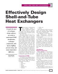
Reverse Osmosis is the technique (also called hyperfiltration) where practically nothing but thesolvent, i.e. water, goes through the membrane. All dissolved substances remain on theconcentrate side.A somewhat different process designed to remove ions, (charged molecules or atoms from asolution) is called Electrodialysis. There the combined effects <strong>of</strong> electrical field and membraneselectivity are used in the separation.Membrane separations, independent <strong>of</strong> the size <strong>of</strong> the entities to be separated, can also beclassified according to the design <strong>of</strong> the modules holding the membranes. Again, please alwaysrefer to the manufacturer’s literature for details. There are many different types, each withadvantages and disadvantages. Plate and spacer modules assembled like a plate heat exchanger,spiral wound modules, hollow fiber modules and tubular modules reminiscent <strong>of</strong> tubular heatexchangers, are the most common ones.Still another way <strong>of</strong> categorizing membranes is by the composition material. It all started withcellulose acetate and derivatives, and then synthetic polymeric membranes appeared, made <strong>of</strong>polysulfone, polyamide, polycarbonate, polyacrylate and many more. Then there are the nonpolymeric,inorganic membranes made <strong>of</strong> carbon with an active layer <strong>of</strong> zirconium oxide andlately the aluminum oxide membranes.One <strong>of</strong> the most important items to consider when talking about cleaning is the particularapplication <strong>of</strong> the membranes. The fouling (soiling <strong>of</strong> the membrane during process) plays amajor role in the success <strong>of</strong> the cleaning procedure. Membranes are used to filter:• cells in biotechnology• valuable drugs in pharmaceutical industry• alcohol in making alcohol free beer• orange and other fruit juices• blood• kraft fluids• oil emulsions• waste water• liquid egg preparations• salt water and many othersThe term sanitation is somewhat unclear and vague. Sometimes it is used to mean cleaning andsanitizing together, as a sort <strong>of</strong> general expression. Sometimes it means the specific step <strong>of</strong> usinga sanitizer to kill bacteria and other microorganisms. We will concentrate on cleaning, theremoval <strong>of</strong> oil in this section. Sanitizing will be discussed separately later.57
When we consider the different possibilities <strong>of</strong> combining the elements previously mentioned:membrane material, module type, filtration technique, and soil composition, then we come upwith a staggering number. Of course, not all combinations are found in practice, but quite a few<strong>of</strong> them are real. For each type <strong>of</strong> soil on each membrane on different modules one might need adifferent cleaning procedure. Cleaning is not a science, although it might merit being one, it isso complex. Membrane cleaning is more an ART than a science due to the variables.Consider the traditional four factors <strong>of</strong> important in cleaning:TimeTemperatureMechanical Action (Energy)Concentration (Chemistry)For membrane cleaning we must go into more detail and add a few items. The water used forcleaning, the membrane material, the module design and the soil have to be considered. We willdiscuss each item separately.TEMPERATURE:An increase in temperature leads to an increase in the speed <strong>of</strong> chemical reactions, doubling themfor every increase <strong>of</strong> 18° F. This is <strong>of</strong> course an approximation valid only within certain limitsand under ideal conditions. But it is true that cleaning is more efficient at higher temperatures.In an alkaline cleaner, the hydrolysis <strong>of</strong> protein speeds up, the solubility <strong>of</strong> most substancesincreases, penetration <strong>of</strong> cleaner into soil accelerates. There is more to temperature when fattysubstances are involved. Here the relationship is not as linear as in chemical reaction. Aphysical phenomenon takes precedence; the melting point. C.I.P. cleaning <strong>of</strong> greasy surfaces atlow temperatures is almost impossible even with the most powerful cleaners unless real solventsare used. However, as soon as the melting range is reached, cleaning becomes easy, so much asthat water alone takes care <strong>of</strong> 95% <strong>of</strong> the fat removal. The chemistry is needed for the final 5%.This sigmoid curve <strong>of</strong> fat removal versus temperature is caused by the drastic change in viscosity<strong>of</strong> the fat film when it melts and to increased surface opens to surfactants when the film spreadout.Once the melting point has been reached, the fat removal is again linearly related to temperature.It would seem logical and pr<strong>of</strong>itable to increase the temperature even more to speed up thecleaning process.However, membrane manufacturers issue very strict limits on the temperature with which themembrane may be treated. They are usually below 140° F, sometimes substantially below. Onlythe inorganic membranes are an exception to the temperature restrictions. What also compoundsthe cleaning problem is that when using strong alkaline cleaners, the temperature allowed is evenlower because <strong>of</strong> the interacting influences <strong>of</strong> pH and heat.Flux rate increase with temperature because <strong>of</strong> the increase in molecular mobility and a certain“widening <strong>of</strong> the pores.” But if the temperature increases considerably beyond58
the endurance <strong>of</strong> the membrane, flux increases are suddenly dramatic and may be irreversible.The retention rate is then compromised and the membrane has to be changed in most cases. Asmuch as it would make cleaning easier sometimes, temperature limits should be strictlyobserved. Experience has shown though, that in general, cleaning temperatures <strong>of</strong> 130° F to140° F are sufficient for most purposes.MECHANICAL ACTIONThe mechanical force or energy put into a cleaning process is <strong>of</strong> great importance. We realizethis when we take the simple case <strong>of</strong> a glass <strong>of</strong> milk. When drained and rinsed with water alone,it will not be clean. But take warm water, rub with your fingers and it will look pretty clean. InC.I.P. cleaning this mechanical energy cannot be generated. The speed <strong>of</strong> flow can be increased;color patterns can be generated that increase the turbulence <strong>of</strong> the fluid. The Reynolds number isa value, which helps to describe the type <strong>of</strong> flow in a system. When the Reynolds number isgreater than about 2000, turbulent flow sets in. It is clear that we get more action at the interface- surface/cleaning solution.It is difficult to measure and study the flow patterns inside <strong>of</strong> modules. One would think thathollow fiber and spiral would modules have no problem generating turbulent flow inside, yet onplate and spacer modules it is not certain that the cleaning solution is turbulent at all stages,everywhere. This could then lead to uneven cleaning results. The design <strong>of</strong> the modules and themembrane shape itself are very important in this respect. In tubular installations a concept hasbeen used which approaches the mechanical effect <strong>of</strong> the brush.Small pellets <strong>of</strong> cotton were introduced in the tubes and flushed through. The cleaning effect isgood but in a big plant it is too time consuming. The effort is not worth it.The best way to obtain turbulent flow is to increase the speed <strong>of</strong> flow. Increasing the pumppressure, on the contrary should not do this, pressure should be reduced wherever possible forcleaning. We do not want to filter the solution more than necessary; rather we want to increasethe shear forces on the membrane surface. The fouling process dictates the method <strong>of</strong> cleaningthe membrane surface. After a period <strong>of</strong> time processing (filtering), the fluxes <strong>of</strong> permeatedecrease. The speed <strong>of</strong> decrease and the amount, depend on many factors:• product filtered• temperature and• total solids to list a fewThe decrease in flux is due to the establishment <strong>of</strong> a layer <strong>of</strong> solutes, <strong>of</strong> macromolecules, whichaccumulate at the membrane surface. The thickness <strong>of</strong> this layer depends on the flowcharacteristics and the concentration <strong>of</strong> the macromolecules in the solution. Higher speed willdecrease the thickness, whereas higher pressure may result in temporary increase <strong>of</strong> flux until anew equilibrium layer thickness has established itself. In cleaning we want to remove this filter“cake” layer. In a conventional filter it could be done by backflushing from the permeate side.In most membrane plants this is not possible because <strong>of</strong> the fragility <strong>of</strong> the membrane and59
ecause <strong>of</strong> the asymmetric surface attached to the support material. It is <strong>of</strong>ten awkward todesign the system for a reversal <strong>of</strong> flow. One must also ask if it really works. In the case <strong>of</strong>particle filtration, where pores may really get clogged with individual cells or granules orwhatever, a backflush has its justification. In UF and RO the picture may be misleading.Molecules are not small balls. Flushing from the other side will not change the adsorptioncharacteristics <strong>of</strong> the soil to the surface much.TIMETime is the factor everybody wants to save, but if the cleaning time is cut too short the resultbecomes uncertain, cleaning may be incomplete. On the other hand, it does not make sense toincrease the cleaning time indefinitely; nothing is gained by it. It may be detrimental. Duringcleaning a certain amount <strong>of</strong> filtering, concentration is going on. Even if we return the permeateto the retentate in the balance tank, diluting the concentrate, soil and detergent solution maydeposit on the membrane surface and form a new polarization layer. The cleaning solutionbecomes saturated after a certain time and cannot continue to remove and hold in suspension anyadditional solids. Ideally, one should use a cleaning solution for a short while, dump it, flushbriefly, prepare a new solution and repeat the process as needed depending on the soil load. If itwere not for the chemical cost and the time involved, this would be the best procedure ascleaning results would be excellent. Too long cleaning times are a waste, plus the shorter thetime the cleaning solution is in contact with the membrane, the better. Practical experience hasshown that in most case 30 minutes for an alkaline wash is sufficient. Only enzyme cleanersmay need more than these; hours and even up to days in difficult cases.SOILAny cleaning procedure must take into account the nature <strong>of</strong> the soil that is to be removed. Thisis true for stainless steel and even more so for membrane surfaces. Cleaning physicsdistinguishes between the forces <strong>of</strong> cohesion and adhesion. In looking at a layer <strong>of</strong> soil it is clearthat the removal <strong>of</strong> the lop layers is governed by the forces <strong>of</strong> molecules sticking together. Theremoval <strong>of</strong> the last layer, the one adhering to the metal or other surface, is governed by theinteraction <strong>of</strong> soil to surface. In the case <strong>of</strong> membranes, this interaction is quite complex. Thereis first the question <strong>of</strong> electrical charges, <strong>of</strong> polarization to consider. When the pH <strong>of</strong> thecleaning solution is different from the pH <strong>of</strong> the soil from production, which is <strong>of</strong>ten the case, thepolarization <strong>of</strong> the surface changes, there by modifying the adhesion <strong>of</strong> the soil to the membrane.In the case <strong>of</strong> inorganic ZrO2 membranes, the polarization follows this curve, whereas onpolymeric membranes we obtain a different picture. This will influence soil components <strong>of</strong> anionic nature (salts, organic acids, amines) and electrically polarized molecules such as proteins.A different adsorption occurs for oily, fatty substances. The adhesion to the membrane is thenthe function <strong>of</strong> the hydrophilic/hydrophobic balance. Hydrophilic means behavior <strong>of</strong> a substancewhich is well soluble in water, miscible with it; hydrophobic is the opposite. Oil is hydrophobic,it will stay on top <strong>of</strong> a water surface, alcohol is hydrophilic, so is sugar, it dissolves and mixesinstantly. Hydrophobic substances attract each other, hydrophilic also tend to stay together. It isno surprise to see those polymeric surfaces such as polysulfones; polyamides and similar types60
are more difficult to degrease, to clean <strong>of</strong> fatty deposits than glass or stainless steel. The fattymolecules adhere to hydrophobic polymers stronger than to hydrophilic glass and need morechemical, physical or mechanical energy for removal. Cellulose acetate membranes are morehydrophilic and from this point <strong>of</strong> view easier to clean than the other membranes were it not forthe severe limitation <strong>of</strong> pH and temperature.An important consideration is also the viscosity <strong>of</strong> the soil or its changes <strong>of</strong> viscosity in contactwith cleaners. In membrane systems it is much more dramatic if a mistake is made in thisrespect than in most other equipment. The equipment can always be dismantled and handcleaned. One cannot do this with most membranes.A chemical reaction can occur between the soil and cleaner coagulation and precipitation <strong>of</strong>protein, for instance; polymerization and plastification in the case <strong>of</strong> the reaction <strong>of</strong> aldehydeswith peptines (polysaccharides used in jam manufacturing) by acids, etc. that can lead to serioustrouble. Laboratory studies in the case <strong>of</strong> previously unknown soil types are recommended, thecouncil <strong>of</strong> experienced personnel in membrane cleaning should be sought BEFORE fouling themembrane.MEMBRANE MATERIAL:A membrane surface is not as smooth as a microscopic scale as a polished metal surface. Underthe powerful microscope it looks like a sponge, which it is in a way. The pores <strong>of</strong> the activefiltrating layer are actually so small that even electron microscopes cannot “see” them, after allthey are <strong>of</strong> the size <strong>of</strong> the molecules to be filtered. Most membrane material is hydrophobic, notliking water very well. When an aqueous solution with high surface tension comes into contactwith a hydrophobic surface full <strong>of</strong> pores and holes, no wetting <strong>of</strong> the pore is achieved. Theaddition <strong>of</strong> surfactants will change this. The choice <strong>of</strong> surfactants depends on the chemicalcomposition <strong>of</strong> the membrane. They must be compatible so that no damage to the membranesurface occurs. This is where much research effort goes in developing cleaners for membranesystems.The polarization potential <strong>of</strong> the membrane material previously mentioned also has an influenceon the choice <strong>of</strong> cleaning procedures. It turns out that organic, polymeric membranes allow forhighest water and product fluxes after cleaning when the last cleaning stop is alkaline. An acidrinse <strong>of</strong>ten leads to decreased water fluxes. On mineral, metallic membranes it is the opposite.This is due to desorption <strong>of</strong> Calcium ions which not only are removed in acid phase bydissolution, but also due to the positive charge on metal at acid pH, they are repulsed from thesurface. Organic polymers become negatively charged at acid pH and will absorb a layer <strong>of</strong>Calcium ions. The use <strong>of</strong> an alkaline last step is therefore recommended in this case.Metallic membranes can even be conditioned in their polarization for the specific type <strong>of</strong> productto be filtered, as the membrane will retain the polarization for quite a while. Charging itpositively for the filtration <strong>of</strong> acid whey will lead to improved filtering capacity, for instance.On polymeric membranes this does not work, as the polarization does not hold long to beeffective. Only chemical modification - attachment <strong>of</strong> specifically charged molecular groups -can achieve this.61
DESIGN:There are many different ways to design a membrane filtration module. From the standpoint <strong>of</strong>cleaning, some are easier to clean than others are, but all have their particular problems.The design has a bearing on the flow pattern and on the type <strong>of</strong> structural support to hold themembrane. In the case <strong>of</strong> tubular membranes and hollow fiber modules, the fibers and/or tubesare arranged in a parallel way. This is more or less identical in design to a tubular heatexchanger. The problem is that if one or more <strong>of</strong> the tubes or fibers are clogged, or <strong>of</strong>ferresistance to flow-through, it is not immediately realized. The fluid chooses the easiest way outand unless noticeable deviations in flux or flow or pressure occur, one might think the module tobe clean.Different module types have different types <strong>of</strong> support structure. In tubular modules, it is mostlythe membrane in form <strong>of</strong> tubes with stainless steel casings. The cleaner must only consider themembrane itself. In plate/spacer modules and in spiral wound modules the cleaning solution canand will come into contact with the glues holding everything together, also with the spacer platesmade <strong>of</strong> plastomers, with the retaining supports for spiral wounds. The compatibility <strong>of</strong> thecleaners with these materials must also be tested, and usually imposes yet another constraint onthe composition <strong>of</strong> the cleaner.Water:Water is a good solvent, a good cleaner all by itself. For cleaning therefore we should strive touse good quality water in order to achieve the best results. Especially in membrane cleaning thequality <strong>of</strong> water is important. Whatever may be in the water could be filtered, concentrated andwould deposit on the membrane surface, clogging it and thereby defeating the whole purpose <strong>of</strong>cleaning.The pH <strong>of</strong> water should be 6-7.5, especially when cleaning Cellulose Acetate membranes, whichare sensitive to higher pH values.The water should not contain any “chlorine” as even low concentrations may, over the longperiods <strong>of</strong> time <strong>of</strong> contact, endanger the membranes. This is particularly true <strong>of</strong> polyamide orthin film composite membranes, which are susceptible to oxidizers.There should not be any considerable amounts <strong>of</strong> solids as they will be filtered out and soil themembranes. The same is true for the bacteriological status. It is not necessary to sterilize thewater before, besides sterilization only kills, it does not remove the microorganisms themselves.Bad water can lead to bacteriological fouling if left standing for a while on membranes. Thereare bacteria, which might attack the membrane and digest it, in the case <strong>of</strong> natural derivatives(CA).62
Metal ions, such as high amounts <strong>of</strong> iron or manganese are detrimental. Their effect iscompounded when higher levels <strong>of</strong> silicate are present. The membranes might start to becomebrownish, blackish, and fluxes go down because <strong>of</strong> the silicate film that is deposited on thesurface; whereas, iron and manganese might still be removable with certain chemical agentsand/or acids (membrane specs permitting), silicates are almost impossible to remove.Hydr<strong>of</strong>luoric acid usually does it, but you might as well throw the membrane out. Operationsucceeded, patient died!High salt content <strong>of</strong> the chloride type is not recommended either. This is less for the benefit <strong>of</strong>the membranes, than for the supporting piping, tanks etc. The combination <strong>of</strong> chlorides withacids causes pitting corrosion and should be avoided!Water hardness can be a big problem. Many plants use water s<strong>of</strong>teners, ion exchangers,permeate water <strong>of</strong>f their RO plant or boiler water for cleaning. The recommended water is thepermeate water. Any water other than permeate may cause irreversible fouling. Check all watersupplies.CHEMISTRY:For membrane cleaning there are basically three types:• Alkaline cleaners with various types <strong>of</strong> buffer systems classifying them according to the pHrange they generate;• Neutral cleaners with or without enzymes;• Acid cleaners.Most cleaning can be done with a good alkaline product. Most types <strong>of</strong> soil that we encounterrequire - or are best removed with alkalinity. Protein, most any kind <strong>of</strong> protein, is more easilyremoved at high pH values. (figure 10.) At these pH values the protein also is slowlyhydrolyzed, making it more soluble. As neutral values are approached, the solubility decreases,and at pH 4-5 many proteins can even be precipitated, they become quite insoluble and difficultto remove.FAT:Under normal conditions <strong>of</strong> cleaning (time, temperature and alkalinity usually encountered), notmuch hydrolysis (called saponification, the making <strong>of</strong> soap) occurs. The higher the alkalinity,the higher the temperature, the more fat will be hydrolyzed, leading to salts <strong>of</strong> fatty acids. IfCalcium ions are around and not enough chelating power is in the cleaner (case <strong>of</strong> commoditycaustic), then Calcium soaps, insoluble deposits will form which can clog up filters and alsomembranes. This should be avoided. Alkalinity based on caustic along, pH, is not sufficient. Itis difficult to control the pH; no buffer system is there; no detergency. There simply is no soilcarrying capacity present. Builders are needed! Sodium or potassium silicate, a favorite builder63
substance is not suitable on membranes. Silicates do not rinse very well, and precipitate easily,especially when pH drops into the acid range.Sodium carbonate, Soda ash or phosphates are good builders and buffer system, however caremust be taken to use well soluble material. Do not use the granular type, which might dissolvetoo slowly and get into the membrane system where it might physically damage the surface byscratching it.The curve <strong>of</strong> protein solubility suggests that the higher the pH the better the cleaning. We alsoknow that in most cases we simply cannot use pH values <strong>of</strong> 13 or more, seldom more than 12.5due to the construction <strong>of</strong> the membrane. Built products have an enormous advantage overstraight caustic. With the inclusion <strong>of</strong> various sequestrants, chelating or complexing agents intothe formula increasing detergency, a built product can allow for the reduction <strong>of</strong> pH whilemaking retention <strong>of</strong> cleaning efficiency possible. Sequestrants also, or primarily, react with theCalcium and magnesium ions present in either the soil or the hard water employed or both. Theyaid greatly in soil removal.NEUTRAL CLEANERS:Neutral cleaners are usually “enzyme cleaners.” Certain membranes, such as the CA and somesensitive composite membranes, do not support pH values higher that 7.5 or 9.5 respectively. Asthe protein solubility curve indicates, this is a bad region for efficient soil removal. In order tomake a product, which is buffered to give a pH value <strong>of</strong> 7.5, or 8 in solution do a good cleaningjob on protein, an enzyme (similar to protease <strong>of</strong> the stomach) is added.The enzyme slowly digests the protein molecules and makes them into water-soluble fragments.To speed up the action <strong>of</strong> the enzyme, one should work at the optimum pH <strong>of</strong> the enzymeactivity, which is about pH 9 (already too high to CA) and at temperature around 120° F whichmay also be too high for some membranes. One could increase the amount <strong>of</strong> enzyme in thecleaner, as more enzyme molecules will be able to do more work. This is however costly.Enzyme cleaners are not only just composed <strong>of</strong> an enzyme preparation, they have builders andbuffers, surfactants for emulsifying and dispersing soil.Depending on the type <strong>of</strong> soil, it is possible to make a neutral cleaner <strong>of</strong> quality without enzymes(a lot less expensive) if no protein is present in the soil or without surfactants when no fat ispresent. Enzymes other than proteases have not been tried on a large scale, mostly because <strong>of</strong>the cost factor involved.ACIDSAn acid cleaning step can <strong>of</strong>ten be skipped when a powerful quality cleaner has been used. It isrecommended to use acids when high amounts <strong>of</strong> mineral deposits, Calcium, Magnesium, Ironare present in the soil or in conditioning the membrane surface in the case <strong>of</strong> inorganicmembranes. A blend <strong>of</strong> acids (nitric/phosphoric/citric) correctly chosen is usually better thanstraight commodities.64
Among other things the blend is easier to handle, has the purity not always found in rawmaterials (an important factor in membrane cleaning) and the benefit <strong>of</strong> the various advantages<strong>of</strong> the pure acids?SOLVENTSSolvents such as chlorinated hydrocarbons or petroleum derivatives are not recommended inmembrane cleaning. Compatibility with the membranes or the support material is <strong>of</strong>ten notassured, cleaning is restricted to only a particular type <strong>of</strong> soil (oil and grease, emulsions), andtoxic and environmental hazards make these cleaners more and more obsolete.OXIDIZERS:Sodium (or potassium) hypochlorite, chlorine bleaches, is <strong>of</strong>ten used for cleaning and sanitizing.It helps in protein removal, but is corrosive, not only on stainless steel, but on certain membranessuch as PA or TC. There are other disadvantages. Even on PS there are limitations as toconcentration and temperature. Again, certain effects seem to work together, but in differentways than on stainless steel. Whereas on steel the recommendation with respect to chlorinatedcleaners is to remain at high pH in order to decrease the chance <strong>of</strong> corrosion, the polymericmaterial suffers more from the combination <strong>of</strong> high alkalinity plus chlorine than from mildalkaline chlorine bleach alone. If membrane specs state temperature range from 60° F to 140° F,pH range 2 to 12 and chlorine level tolerated up to 300 PPM, that does NOT mean that it is safeto operate at 140°F, pH 12 and 300 PPM simultaneously.The temperature tolerance is given at similar conditions. What one can do is a matter <strong>of</strong>negotiation between the user, the manufacturer and the supplier.HYDROGEN PEROXIDE:Hydrogen peroxide is used as a cleaning booster in some applications, not as effective aschlorine, but also not as destructive. In membrane systems it is sometimes used for cleaning andonce again, but cautioned to review the membrane specifications before use.65
CIP Water QualityWater used for flushing, cleaning and disinfecting <strong>of</strong> membrane filtration plants mustconform to the following standards to obtain best possible service.It is a prerequisite that the following standards be adhered to for membraneguarantee to be valid. It is also recommended that the water be analyzed atleast every three months to ensure proper quality. If the water quality does notmeet these standards, consult a Niro representative. Every six months themust be sent to Niro for review.analysis• Iron Less than 0.05 PPM• Manganese (MN) Less than 0.02 PPM• Silicate (Si0 2 ) Less than 10 PPM• Aluminum (Al) Less than 1 PPM• Hardness as (CaCO 2 ) Less than 10 gr/gal (170 PPM)• Particles Less than 25 microns• Turbidity Less than 1 NTU• Silt Index Less than 2.5 SDI• Total Plate Count Less than 1000 per ml• Coli Count 0 per 100 ml• Chlorine (RO and NF only) 0 PPM66
Oxidizer IntoleranceIf you have a reverse osmosis or nano-filtration system, the membranes have no tolerancefor oxidizers. Introduction <strong>of</strong> any oxidizers, especially chlorine (sodium hypochlorite),will cause permanent damage.Niro will not assume any responsibility for damaged membranes <strong>of</strong> oxidizers come incontact with the membrane.Defoamer IntoleranceUse <strong>of</strong> anti-foaming agents is not recommended since they can cause irreversible loss <strong>of</strong>flux.* If use <strong>of</strong> anti-foaming is necessary, please consult a Niro representative.No chemical that has not been approved by Niro should be used for membrane cleaningor shall come in contact with the membranes.Niro will not assume any responsibility for damaged membranes if unapproved chemicalscome in contact with the membranes.A common component <strong>of</strong> anti-foaming agents in silicon, which is the primary cause <strong>of</strong>the flux loss. Silicon is also found in many lubricants, which also should not comein contact with the67