HYDRA CELL Manuale Uso e Manutenzione ... - Asco Pompe Srl
HYDRA CELL Manuale Uso e Manutenzione ... - Asco Pompe Srl
HYDRA CELL Manuale Uso e Manutenzione ... - Asco Pompe Srl
- No tags were found...

You also want an ePaper? Increase the reach of your titles
YUMPU automatically turns print PDFs into web optimized ePapers that Google loves.
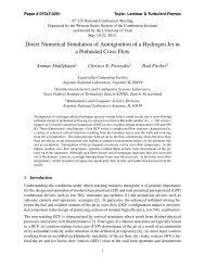
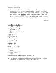
D/G-10 SpecificationsPerformance* Net Positive Suction Head –NPSHr*RPM0 200 400 600 800 1000 1200 1400 1600 180010.038.02417507Gallons Per Minute9.08.07.06.05.04.0200 PSI (14 bar)500 PSI (35 bar)1000 PSI (70 bar)D/G-10-X1450D/G-10-ED/G-10S175036.034.032.030.028.026.024.022.020.018.016.014.0Liters Per MinuteNPSHr (feet of water)20161284D/G-10-XD/G-10-ED/G-10-SD/G-10-I000 200 400 600 800 1000 1200 1400 1600 1800RPM1450654321NPSHr (meters of water)3.0D/G-10-I12.010.0Dry Lift*2.01.00* Specifications depict D/G-10 metallic and non-metallic pumphead models only. Contact factory or visit our website(www.hydra-cell.com) for performance specifications on slurryduty (SD) models.8.06.04.02.00Lift (feet of water)87654321D/G-10-XD/G-10-ED/G-10-SD/G-10-I145017502.52.01.51.00.5Lift (meters of water)00200 400 600 800 1000 1200 1400 1600 1800RPM03 D10-991-2400 5/1/04
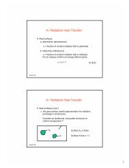
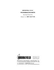
D/G-10 DimensionsModels with Metallic Pumping HeadBrassCast Iron316 Stainless SteelNickel Alloy (C Series)7.3(185.4)OutletD-10: 3/4" NPTG-10: 3/4" BSPT9.5(241.3)0.188(4.78)Ø0.8754.3 (22.23)(109.2)2.2(55.9)1.1(27.9)2.4(60.9)OUTIN3.4(86.4)3.1(78.7)1.8(45.7)2.0(50.8)3.0(76.2)11.2(284.5)4.4(111.8)1.9(48.3)Drain 1/8" NPT5.0(127)2.5(63.5)InletD-10: 1" NPTG-10: 1" BSPTModels with Non-Metallic or Slurry Duty (SD) Pump HeadKynar ®PolypropyleneCelcon7.25(184.2)OutletD-10: 3/4" NPTG-10: 3/4" BSPT9.5(241.3)0.188(4.78)2.2(55.9)OUT0.97(24.6)Ø0.875(22.23)4.3(109.2)2.4(60.9)IN0.56(14.2)1.8(45.7)2.0(50.8)3.0(76.2)12.2(309.9)11.8(299.7)2.5(63.5)5.0(127)0.4(10.2)Drain1/8" NPT5.0(127)2.5(63.5)InletD-10: 1" NPTG-10: 1" BSPT4 D10-991-2400 5/1/04
D/G-10 InstallationLocationLocate the pump as close to the supply source as possible.Install it in a lighted clean space where it will be easy to inspectand maintain. Allow room for checking the oil level, changingthe oil, and removing the pump head (manifold, valve plate andrelated items).MountingThe pump shaft can rotate in either direction.To prevent vibration, mount the pump and motor securely on alevel rigid base.On a belt-drive system, align the sheaves accurately; pooralignment wastes horsepower and shortens the belt and bearinglife. Make sure the belts are properly tightened, as specified bythe belt manufacturer.On a direct-drive system, align the shafts accurately. Unlessotherwise specified by the coupling manufacturer, maximumparallel misalignment should not exceed 0.015 in. (0.4 mm)and angular misalignment should be held to 1° maximum.Careful alignment extends life of the coupling, pump, shafts,and support bearings. Consult coupling manufacturer for exactalignment tolerances.Important PrecautionsAdequate Fluid Supply. To avoid cavitation andpremature pump failure, be sure that the pump will havean adequate fluid supply and that the inlet line will not beobstructed. See “Inlet Piping”.Positive Displacement. This is a positive-displacementpump. To avoid severe system damage if the dischargeline ever becomes blocked, install a relief valvedownstream from the pump. See “Discharge Piping”.Safety Guards. Install adequate safety guards over allpulleys, belts, and couplings. Follow all codes andregulations regarding installation and operation of thepumping system.Shut-Off Valves. Never install shut-off valves betweenthe pump and discharge pressure regulator, or in theregulator bypass line.Freezing Conditions. Protect the pump from freezing.See also the Maintenance Section.Consult the Factory for the following situations:• Extreme temperature applications – above 160° F (71°C) or below 40° F (4.4° C)• Pressure feeding of pumps• Viscous or abrasive fluid applications• Chemical compatibility problems• Hot ambient temperatures – above 110° F (43° C)• Conditions where pump oil may exceed 200° F (93°C) because of a combination of hot ambienttemperatures, hot fluid temperature, and fullhorsepower load — an oil cooler may be required5 D10-991-2400 5/1/04
D/G-10 InstallationInlet Piping (Suction Feed)CAUTION: When pumping at temperatures above 160° F(71° C), use a pressure-feed system.Install draincocks at any low points of the suction line, to permitdraining in freezing conditions.Provide for permanent or temporary installation of a vacuumgauge to monitor the inlet suction. To maintain maximum flow,vacuum at the pump inlet should not exceed 7 in. Hg at 70° F(180 mm Hg at 21° C). Do not supply more than one pumpfrom the same inlet line.Supply TankUse a supply tank that is large enough to provide time for anytrapped air in the fluid to escape. The tank size should be atleast twice the maximum pump flow rate.Isolate the pump and motor stand from the supply tank, andsupport them separately.Install a separate inlet line from the supply tank to each pump.Install the inlet and bypass lines so they empty into the supplytank below the lowest water level, on the opposite side of thebaffle from the pump suction line.If a line strainer is used in the system install it in the inlet line tothe supply tank.To reduce aeration and turbulence, install a completelysubmerged baffle plate to separate the incoming and outgoingliquids.Install a vortex breaker in the supply tank, over the outlet portto the pump.Place a cover over the supply tank, to prevent foreign objectsfrom falling into it.Hose and RoutingSize the suction line at least one size larger than the pumpinlet, and so that the velocity will not exceed 1-3 ft/sec (0.3 to0.9 m/s):For pipe in inches: Velocity (ft/sec) = 0.408 x GPM/Pipe ID 2For pipe in mm: Velocity (m/sec) = 21.2 x LPM/Pipe ID 2Keep the suction line as short and direct as possible. A maximumof 3 feet (1 m) is recommended.Use flexible hose and/or expansion joints to absorb vibration,expansion, or contraction.If possible, keep the suction line level. Do not have any highpoints to collect vapor unless these high points are vented.To reduce turbulence and resistance, do not use 90° elbows. Ifturns are necessary in the suction line, use 45° elbows orarrange sweeping curves in the flexible inlet hose.If a block valve is used, be sure it is fully opened so that theflow to the pump is not restricted. The opening should be atleast the same diameter as the inlet plumbing ID.Do not use a line strainer or filter in the suction line unlessregular maintenance is assured. If used, it should have a freeflowarea of at least three times the free-flow area of the inlet.Install piping supports where necessary to relieve strain on theinlet line and to minimize vibration.Loctite is a registered trademark of Loctite Corporation.Teflon is a registered trademark of E. I. DuPont de Nemours & Co. Inc.Scotchbrite is a registered trademark of 3M Company.Inlet Piping (Pressure Feed)Provide for permanent or temporary installation of a vacuum/pressure gauge to monitor the inlet vacuum or pressure.Pressure at the pump inlet should not exceed 250 psi (17 bar);if it could get higher, install an inlet pressure reducing regulator.Do not supply more than one pump from the same inlet line.Inlet CalculationsAcceleration HeadCalculating the Acceleration HeadUse the following formula to calculate acceleration head losses.Subtract this figure from the NPSHa, and compare the result tothe NPSHr of the Hydra-Cell pump.Ha = (L x V x N x C) ÷ (K x G)where:Ha = Acceleration head (ft of liquid)L = Actual length of suction line (ft) — not equivalent lengthV = Velocity of liquid in suction line (ft/sec) [V = GPM x (0.408÷ pipe ID 2 )]N = RPM of crank shaftC = Constant determined by type of pump — use 0.066 forthe D-10 and G-10 Hydra-Cell pumpsK = Constant to compensate for compressibility of the fluid— use: 1.4 for de-aerated or hot water; 1.5 for mostliquids; 2.5 for hydrocarbons with high compressibilityG = Gravitational constant (32.2 ft/sec 2 )Friction LossesCalculating Friction Losses in Suction PipingWhen following the above recommendations (under “InletPiping”) for minimum hose/pipe I.D. and maximum length,frictional losses in the suction piping are negligible (i.e., Hf = 0)if you are pumping a water-like fluid.When pumping more-viscous fluids such as lubricating oils,sealants, adhesives, syrups, varnishes, etc., frictional lossesin the suction piping may become significant. As Hf increases, theavailable NPSH (NPSHa) will decrease, and cavitation will occur.In general, frictional losses increase with increasing viscosity,increasing suction-line length, increasing pump flowrate, anddecreasing suction-line diameter. Changes in suction-linediameter have the greatest impact on frictional losses: a 25%increase in suction-line diameter cuts losses by more than twotimes, and a 50% increase cuts losses by a factor of five times.Consult the factory before pumping viscous fluids.Minimizing Acceleration Head and Frictional LossesTo minimize the acceleration head and frictional losses:• Keep inlet lines less than 3 ft (1 m) long• Use at least 1-1/2 in. (38 mm) I.D. inlet hose• Use soft hose (low-pressure hose, noncollapsing) for theinlet lines• Minimize fittings (elbows, valves, tees, etc.)• Use a suction stabilizer on the inlet.6 D10-991-2400 5/1/04
D/G-10 InstallationNet Positive Suction HeadNPSHa must be equal to or greater than NPSHr. If not, thepressure in the pump inlet will be lower than the vapor pressureof the fluid — and cavitation will occur.Calculating the NPSHaUse the following formula to calculate the NPSHa:NPSHa = Pt + Hz - Hf - Ha - Pvpwhere:Pt = Atmospheric pressureHz = Vertical distance from surface liquid to pump centerline (ifliquid is below pump centerline, the Hz is negative)Hf = Friction losses in suction pipingHa = Acceleration head at pump suctionPvp = Absolute vapor pressure of liquid at pumping temperatureNOTES:• In good practice, NPSHa should be 2 ft greater than NPSHr• All values must be expressed in feet of liquidAtmospheric Pressure at Various AltitudesAltitude Pressure Altitude Pressure(ft) (ft of H 2O) (ft) (ft of H 2O)0 33.9 1500 32.1500 33.3 2000 31.51000 32.8 5000 28.2Discharge PipingHose and RoutingUse the shortest, most-direct route for the discharge line.Select pipe or hose with a working pressure rating of at least1.5 times the maximum system pressure. EXAMPLE: Select a1500-psi W.P.-rated hose for systems to be operated at 1000-psi-gauge pressure.Use about 6 ft (1.8 m) of flexible hose between the pump andrigid piping to absorb vibration, expansion or contraction.Support the pump and piping independently. Size the dischargeline so that the velocity of the fluid will not exceed 7-10 ft/sec(2-3 m/sec):For pipe in inches: Velocity (ft/sec) = 0.408 x GPM/Pipe ID 2For pipe in mm: Velocity (m/sec) = 21.2 x LPM/Pipe ID 2NOTE: Pumps with non-metallic pumping head arelimited to 250 psi (17 bar) maximum working pressurerating.Pressure RegulationInstall a pressure regulator or unloader in the dischargeline. Bypass pressure must not exceed the pressure limit ofthe pump.Size the regulator so that, when fully open, it will be large enoughto relieve the full capacity of the pump without overpressurizingthe system.Locate the valve as close to the pump as possible and aheadof any other valves.Adjust the pressure regulating valve to no more than 10% overthe maximum working pressure of the system. Do not exceedthe manufacturer’s pressure rating for the pump or regulator.Route the bypass line to the supply tank, or to the suction lineas far as possible from the pump (to reduce the chance ofturbulence and cavitation).If the pump may be run for a long time with the discharge closedand fluid bypassing, install a thermal protector in the bypassline (to prevent severe temperature buildup in the bypassedfluid).CAUTION: Never install shutoff valves in the bypass lineor between the pump and pressure regulator.Provide for permanent or temporary installation of a pressuregauge to monitor the discharge pressure at the pump.For additional system protection, install a safety relief valve inthe discharge line, downstream from the pressure regulator.7 D10-991-2400 5/1/04
D/G-10 InstallationBefore Initial Start-UpBefore you start the pump, be sure that:• All shutoff valves are open, and the pump has an adequatesupply of fluid.• All connections are tight.• The oil level is 1/4 in. (6 mm) above the cast surface in theupper oil reservoir.• The relief valve on the pump outlet is adjusted so the pumpstarts under minimum pressure.• All pulleys and belts are properly aligned, and belts aretensioned according to specification.• All pulleys, belts and shaft couplings have adequate safetyguards.Initial Start-Up Procedure1. Turn on power to the pump motor.2. Check the inlet pressure or vacuum. To maintain maximumflow, inlet vacuum must not exceed 7 in. Hg at 70° F (180mm Hg at 21° C). Inlet pressure must not exceed 250 psi(17 bar).3. Listen for any erratic noise, and look for unsteady flow. Ifthe pump does not clear, refer to the TroubleshootingSection.4. If the system has an air lock and the pump fails to prime:a. Turn off the power.b. Remove the pressure gauge or plug from the tee fittingat the pump outlet (refer to the illustration on page 5).NOTE: Fluid may come out of this port when the plugis removed. Provide an adequate catch basin for fluidspillage, if required. Fluid will come out of this port whenthe pump is started, so we recommend that you attachadequate plumbing from this port so fluid will not besprayed or lost. Use high-pressure-rated hose andfittings from this port. Take all safety precautions toassure safe handling of the fluid being pumped.c. Jog the system on and off until the fluid coming from thisport is air-free.d. Turn off the power.e. Remove the plumbing that was temporarily installed, andreinstall the pressure gauge or plug.5. Adjust the discharge pressure regulator to the desiredoperating and bypass pressures. Do not exceed themaximum pressure rating of the pump.6. After the pressure regulator is adjusted, set the safety reliefvalve at 100 psi (7 bar) higher than the desired operatingpressure. To verify this setting, adjust the discharge pressureregulator upward until the relief valve opens. Follow therecommendations in the above NOTE (step 4b) for handlingthe fluid that will come from the relief valve.7. Reset the discharge pressure regulator to the desired systempressure.8. Provide a return line from the relief valve to the supply tank,similar to the bypass line from the pressure regulator.8 D10-991-2400 5/1/04
D/G-10 MaintenanceNOTE: The numbers in parentheses are the ReferenceNumbers on the exploded view illustrations found in thismanual and in the Parts Manual.DailyCheck the oil level and the condition of the oil. The oil levelshould be 1/4 in. (6 mm) from the top of the fill port.Use the appropriate Hydra-Oil for the application (contactWanner Engineering if in doubt).CAUTION: If you are losing oil but don’t see any externalleakage, or if the oil becomes discolored and contaminated,one of the diaphragms (20) may be damaged. Refer to theFluid-End Service Section. Do not operate the pump with adamaged diaphragm.CAUTION: Do not leave contaminated oil in the pumphousing or leave the housing empty. Remove contaminatedoil as soon as discovered, and replace it with clean oil.PeriodicallyChange the oil after the first 100 hours of operation, and thenaccording to the guidelines below.Hours Between Oil Changes @ VariousProcess Fluid Temperatures
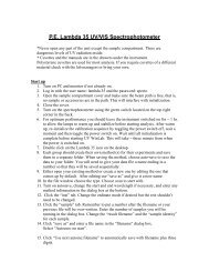
D/G-10 Service (Fluid End)NOTE: The numbers in parentheses are the ReferenceNumbers on the exploded view illustrations found in thismanual and also in the Parts Manual.This section explains how to disassemble and inspect all easilyserviceableparts of the pump. Repair procedures for thehydraulic end (oil reservoir) of the pump are included in a latersection of the manual.CAUTION: Do not disassemble the hydraulic end unlessyou are a skilled mechanic. For assistance, contact WannerEngineering (TEL 612-332-5681 or FAX 612-332-6937) or thedistributor in your area.CAUTION: The two bolts (29; 25 or 44) that screw throughthe back of the housing into the cylinder casting hold thecasting over the hydraulic end of the pump. Do not removethem except when repairing the hydraulic end.Model D-10/G-10With Non-Metallic Pump Head*1. Remove Manifold (6), ValvePlate (16)a. Remove all nuts (31) and bolts (4) around the manifold. Donot remove the two bolts (29; 25 or 44) that are installedthrough the back of the pump housing.b. Use a 3/8-in. (10-mm) hex Allen wrench to remove thecenterbolt (1) and its washer (2).CAUTION: Do not turn the pump drive shaft while themanifold and valve plate are off the pump, except whenremoving diaphragms or repriming the hydraulic cells.c. Remove the manifold (6), and support plate (42) [nonmetallicpump head only]. The valve plate (16) will remainon the cylinder casting (24).d. Inspect the manifold for warping or wear around the inletand outlet ports. If wear is excessive, replace the manifold.To check if the manifold is warped, remove the O-rings andplace a straightedge across it. A warped manifold should bereplaced.*NOTE: For non-metallic slurry duty pumps, see theinsert to this manual for fluid valve service (Step 2),then proceed to Step 3 in this manual for remainingservice steps.10 D10-991-2400 5/1/04
D/G-10 Service (Fluid End)11 D10-991-2400 5/1/04
D/G-10 Service (Fluid End)2. Inspect Valves (10-15, 39)*NOTE: For non-metallic slurry duty pumps, see the insertto this manual for fluid valve service (Step 2), then proceedto Step 3 in this manual for remaining service steps.The three inlet and three outlet valve assemblies are identical(but face in opposite directions). Inspect each valve as follows:a. Check the spring retainer (15), and replace if worn.Note: if your pump has either abrasive duty valveassemblies or a non-metallic pump head there will be aplastic dampening washer (39) at the bottom of eachseat. Inspect each one for wear or cracks and replace ifnecessary.b. Check the valve spring (13). If it is shorter than a new spring,replace it (don’t just stretch the old spring).c. Check the valve poppet (12). If worn excessively, replace it.NOTE: If your pump has plastic spring retainers, thereis a tetra seal (flat O-ring, 14) between the retainer (15)and valve seat (11).d. Remove the valve seat (11). A seat remover is included inthe Wanner Tool Kit. Inspect the valve seat for wear, andreplace it if necessary.e. Reinstall the valve assemblies:• Clean the valve ports and shoulders with emery cloth,and lubricate them with lubricating gel or petroleum jelly.• Install the O-ring (10) on the valve seat (11).• Inlet (3 center valves). Insert the spring retainer (15)into the valve plate, then insert the spring, valve, andvalve seat (13,12,11).If the pump has plastic springretainers, a flat O-ring (14) goes between the retainerand seat. Insert dampening washer (39) if included inyour valve assembly.• Outlet (3 outer valves). Insert dampening washer (39)if included in your valve assembly.Insert the valve seat,valve, and spring, then the retainer. If the pump hasplastic retainers, install the flat O-ring between theretainer and seat. If the pump has metal spring retainersin the outlet valves, position them so a leg does not pointtoward the center of the pump (refer to the illustrationbelow).WRONG: Retainerleg pointing towardcenter of pump.Installing Valve RetainersInto Valve Plate3. Inspect and ReplaceDiaphragms (20)If necessary to service the diaphragms, remove the two socketheadcap screws (41) that secure the valve plate (16) to thecylinder casting (24). Inspect the valve plate in the same manneras you did the manifold.a. Lift the diaphragm by one edge, and turn the pump shaftuntil the diaphragm pulls up. This will expose machinedcross-holes in the plunger shaft behind the diaphragm.b. Insert an Allen wrench through one of the holes, to hold thediaphragm up. The proper size tool is included in the WannerTool Kit.c. Remove the screw (17), O-ring (18), and follower (19) inthe center of the diaphragm.d. Remove the diaphragm, and inspect it carefully. A ruptureddiaphragm generally indicates a pumping system problem,and replacing only the diaphragm will not solve the largerproblem. Inspect the diaphragm for the following:• Half-moon marks. Usually caused by cavitation of thepump (refer to the “Troubleshooting” section).• Concentric circular marks. Usually caused bycavitation of the pump (refer to the “Troubleshooting”section).• Small puncture. Usually caused by a sharp foreignobject in the fluid, or by an ice particle.• Diaphragm pulled away from the center screw or fromthe cylinder sides. Usually caused by fluid being frozenin the pump, or by overpressurization of the pump.• Diaphragm becoming stiff and losing flexibility. Usuallycaused by pumping a fluid that is incompatible with thediaphragm material.• Slice in ridge of diaphragm. Occurs when a Vitondiaphragm is operated at cold temperatures.• Diaphragm edge chewed away. Usually caused byoverpressurizing the system.e. Inspect the plunger (21) for any rough surfaces or edges.Do not remove the plunger from the plunger shaft. Smooththe surfaces and edges as necessary with emery cloth or afine file.CAUTION: If a diaphragm has ruptured and foreignmaterial or water has entered the oil reservoir, do notoperate the pump. Check all diaphragms, then flush thereservoir completely (as outlined below) and refill it withfresh oil. Never let the pump stand with foreign materialor water in the reservoir, or with the reservoir empty.f. Install a new diaphragm (or reinstall the old one, asappropriate), ridge side out.g. Clean the screw (17) and remove any oil from it. Applymedium-strength threadlocker to the screw. Reinstall thescrew and follower (19), and a new O-ring (18). Tighten to18 in.-lbs (2.0 N-m).h. Repeat the above inspection procedure (and replacement,if necessary) with the other two diaphragms.RIGHT12 D10-991-2400 5/1/04
D/G-10 Service (Fluid End)4. Flush Contaminant fromHydraulic End(only if a diaphragm has ruptured)a. Remove the oil drain cap (34) and allow all oil andcontaminate to drain out.b. Fill the reservoir with kerosene or solvent, manually turnthe pump shaft to circulate the kerosene, and drain.CAUTION: If you have EPDM diaphragms, or if foodgrade oil is in the reservoir, do not use kerosene orsolvents. Instead, flush with the same lubricant that isin the reservoir. Pumps with EPDM diaphragms havean “E” as the 7th digit of the Model No.c. Repeat the flushing procedure (step b).d. Fill the reservoir with fresh oil, manually turn the pump shaftto circulate the oil, and drain once again.e. Refill the reservoir. If the oil appears milky, there is stillcontaminate in the reservoir. Repeat the flushing procedureuntil the oil appears clean.5A. Prime the Hydraulic Cells onStandard Pumpsa. With the pump horizontal, and the fluid-end head removed,fill the reservoir with the appropriate Hydra-oil for theapplication. Have a catch basin for oil that leaks from behindthe diaphragms when priming. Catch the oil and dispose ofit properly; do not reuse it.b. All air in the oil within the hydraulic cell (behind thediaphragms) must be forced out by turning the shaft (andthus pumping the piston). A shaft rotator is included in theWanner Tool Kit. Turn the shaft until a bubble-free flow of oilcomes from behind all the diaphragms. Watch the oil levelin the reservoir; if it gets too low during priming, air will bedrawn into the pistons (inside the hydraulic end) and willcause the pump to run rough.c. Wipe excess oil from the cylinder casting (24) anddiaphragms (20).d. Ensure that the oil is 1 inch (25 mm) from the top of the fill port.e. Replace oil fill cap (27).5B. Priming the Hydraulic Cellsfor Kel-Cell PumpsNOTE: Providing oil prime to Kel-Cell fitted pumps requirespressure be applied to the diaphragms. This can be donemanually, with the system head pressure, or withpressurized air if available. Review all methods below todetermine the procedure most suitable.Method #1 (system head pressure less than 2 psi)a. Install the valve plate (16) but without the outlet valvesinstalled (or else remove the outlet valves; leave the seatsinstalled) onto the cylinder housing. Tighten the two socketheadscrews (41).b. Fill the reservoir with appropriate Hydra-oil to the fill port.c. With a blunt pointer (eraser end of pencil), reach in througheach outlet valve port and push the follower-diaphragmbackwards. Note the air bubbles coming out at the oil fillport. Now turn the shaft about 1/2 turn.d. Repeat depressing diaphragms and rotating shaft (approx.4-6 times) until no more air bubbles escape and the oil hasdropped about 1 inch (25 mm) from the top of the fill port.The hydraulic cells are now primed. Replace the oil fill cap.e. Install outlet valve assemblies in each outlet valve port. SeeParts Manual for correct assembly order. You may have totip pump (head upward) in order to keep the valve centeredon the seat and allow the retainer to fit all the way into portflush.f. Install manifold (6) and complete installation.Alternative Method #1:With the pump horizontal, and the fluid-end head removed, fillthe reservoir with the appropriate Hydra-oil for the application.Have a catch basin for oil that leaks from behind the diaphragmswhen priming. Catch the oil and dispose of it properly; do notreuse it.a. All air in the oil within the hydraulic piston behind thediaphragms must be forced out by turning the shaft (andthus pumping the piston). A shaft rotator is included in theHydra-Cell Tool Kit. Keep pressure on the diaphragms whileturning the shaft until a bubble-free flow of oil comes frombehind all the diaphragms. Maintain the oil level in thereservoir. Do not allow oil level to be lower than the reservoir.b. Quickly attach the loaded valve plate (16) (before the oilruns out past the diaphragms) with socket head screws (41),but do not tighten completely. Leave a gap between the valveplate and the cylinder housing. Turn the shaft 2-3 turns tofinish forcing out air behind the diaphragms. The hydrauliccells are now primed. Now finish tightening the valve platewith the two socket head screws and add pump manifold.c. Wipe excess oil from around the pump head.d. Check that the oil level is 1 inch (25 mm) from the top of thefill port.e. Replace the oil fill cap and complete installation.13 D10-991-2400 5/1/04
D/G-10 Service (Fluid End)Method #2 (head pressure greater than 2 psi)This simple and clean method of priming the Hydra-cellsrequires an inlet head pressure of at least 5 feet (1.5 m) or 2psi (.14 bar). The pressure source is required to hold thediaphragms back while the piston moves so as to force out the air.Completely assemble the pump and fill the reservoir with theappropriate Hydra-oil to the fill port.a. When tank head pressure is being used to prime, installthe pump back into the system and connect the tank supplyline to pump inlet. Pump discharge line may be connectedat this time, but end of line must be open to allow air to passout.b. Slowly turn the pump shaft by hand and watch for bubblesexiting the oil reservoir fill opening. This will take severalrotations; when no more bubbles come out and the reservoirlevel has dropped about 1” (25 mm), the hydraulic cells areprimed.c. Replace the oil fill cap and complete installation.d. When compressed air is being used to prime, insert aclean air hose to the pump inlet and restrict the pump outlet.Turn the shaft a quarter turn and then apply air pressureinto the manifold to put pressure on the diaphragms. Thiswill force air out from inside the pistons and you will seebubbles at the reservoir opening. Repeat for severalrotations until no more air bubbles come out and the reservoirlevel has dropped about 1” (25 mm). The hydraulic cells arenow primed.e. Replace the oil fill cap and complete installation.6. Reinstall Pumping HeadMODEL D-10NOTE: Use the bolt (29) protruding through the cylindercasting at the 10 o-clock position to locate the valve plateon the cylinder casting. Place the “blind hole” on the valveplate over this bolt.a. Reinstall the valve plate (16), with the valve assembliesinstalled as outlined above, onto the cylinder casting.Recheck that the blind hole is over the protruding bolt at the10 o-clock position. Install the socket-head cap screws (41)and secure the valve plate to the cylinder casting.b. Reinstall the O-rings (7,8,9) on the rear side of the manifold.Use petroleum jelly or lubricating gel to hold them in place.c. Reinstall the manifold onto the valve plate. Be sure the drainplug (3) is at the bottom of the manifold.NOTE: on pumps with non-metallic head positionsupport plate (42) onto manifold with ports and boltholes aligned properly.d. Insert all bolts (4), washers (5), and nuts (31). Hand tighten.e. Reinstall the centerbolt (1) with its washer (2), and torqueto 45 ft-lbs.f. Alternately tighten perimeter bolts (4) until all are secure.Torque to 45 ft-lbs.g. Recheck all bolts for tightness.MODEL G-10NOTE: Use the bolt (29) protruding through the cylindercasting at the 10 o’clock position to locate the valve plateon the cylinder casting. Place the “blind hole” on the valveplate over this bolt.a. Reinstall the valve plate (16), with the valve assembliesinstalled as outlined above, onto the cylinder casting.Recheck that the blind hole is over the protruding bolt at the10 o’clock position. Install the two socket-head cap screws(41) and secure the valve plate to the cylinder casting.b. Reinstall the O-rings (7,8,9) on the rear side of the manifold.Use petroleum jelly or lubricating gel to hold them in place.c. Reinstall the manifold onto the valve plate. Be sure the drainplug (3) is at the bottom of the manifold.NOTE: on pumps with non-metallic head positionsupport plate (42) onto manifold with ports and boltholes aligned properly.d. Insert all six bolts (4) around the edge of the manifold.Reinstall the pump centerbolt (1) with its washer (2).e. Alternately tighten perimeter bolts (4) until all are secure.Torque to 54 N-m.f. Tighten the pump centerbolt. Torque to 54 N-m.g. Recheck all bolts for tightness.14 D10-991-2400 5/1/04
D/G-10 Service (Hydraulic End)15 D10-991-2400 5/1/04
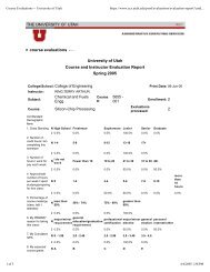
D/G-10 Service (Hydraulic End)NOTE: The numbers in parentheses are the ReferenceNumbers on the exploded view illustrations found in thismanual and also in the Parts Manual.CAUTION: Do not disassemble the hydraulic end of thepump unless you are a skilled mechanic. For assistance,contact Wanner Engineering (TEL 612-332-5681 or FAX 612-332-6937) or the distributor in your area.CAUTION: The two bolts (29; 25 or 44) that screw throughthe back of the housing into the cylinder housing (24) holdthe housing to the pump housing. Do not remove themexcept when repairing the hydraulic end.NOTE: The following service procedures refer several timesto the Wanner Tool Kit (P/N A03-175-1101). We strongly urgeyou not to try to repair the hydraulic end of the pumpwithout using the tools in this kit (available from Wanneror your local distributor).2. Disassemble Pistonsa. With the pump housing removed (see above), turn the unitover and set it on a flat surface, piston side down.b. With the diaphragms removed (see the Fluid-End ServiceSection), reinsert a follower screw (17) into the hole in oneof the valve plungers (54). Tap the screw lightly with ahammer; the plunger (21) should slip off the valve plunger(54).The hydraulic piston assembly (50-59) can now bedisassembled. Inspect all parts, and replace all O-rings andany other parts that are worn or damaged.c. Repeat step b for the remaining pistons.NOTE: When you reassemble the hydraulic piston, usenew plungers (21). They are press-fit onto the valveplungers (54) and are not reusable.3. Reassemble Pistonsa. Drop a ball (58) into each opening in the bottom of a pistonassembly (59).b. Insert a retaining washer (57) and O-ring (56) to hold theballs in place.c. Insert a valve plunger (54) into a valve cylinder (55). Slide aspring (53) over the plunger, inside the valve cylinder.d. Insert an O-ring (52) into a spring retainer (51).e. Slide the assembled valve cylinder, plunger, and spring (53-55) into the spring retainer (51).f. Slide the complete cylinder-and-retainer assembly (51-55)into the piston assembly (59).g. Insert a return spring (50) into the piston assembly, wideend first. This is a tight fit, and can best be done by “screwing”the spring in counterclockwise.h. Repeat the above procedure for the other two pistons.1. Remove Pump Housinga. Remove the head of the pump, and the diaphragms, asoutlined in the Fluid-End Service Section.b. Drain the oil from the pump housing by removing the drainplug (34).c. Set the hydraulic end of the pump face-down on the cylinderhousing (24), onto a smooth, clean surface.d. Check the shaft for sharp burrs. Smooth any burrs, to preventscarring the housing seals (64) when you disassemble thepump.e. Remove the bolts (29; 25 or 44) that secure the housing tothe cylinder casting. The piston return springs (50) will forcethe cylinder housing and housing apart.NOTE: When reassembling later, note that one bolt (29)is 1/4" (5 mm) longer than the other (25 or 44). Thelonger bolt must be installed in the 10 o’clock positionof the cylinder housing (24).f. Lift off the housing (30).g. Inspect the cam and bearings (62), and the bearing race inthe rear of the housing. If the bearings are pitted or binding,or if the housing race is worn, replace them both.4. Reassemble Pump Housingand Cylinder HousingNOTE: Inspect the shaft seals (64) before continuing. Ifthey look damaged in any way, replace them (remove bypounding them out from inside the pump housing). Bothseals should be replaced at the same time. Clean the borein the housing using emery cloth or ScotchBrite.a. Place the cylinder housing (24) face-down on a flat surface.b. Insert the assembled pistons (50-59) into the cylinderhousing. The holes on the foot end of the pistons should allpoint toward the center of the casting.c. Note the location of the outer ring of holes in the cylinderhousing and in the pump housing flange (in particular, theholes where bolts 29 and 25 or 44 will be installed).d. Stand the camshaft assembly (62) on the cylinder housing(24).CAUTION: The pilot bearing MUST be properly nestedin the bearing race during assembly. If misaligned, thebearing will be damaged and the pump will fail withinthe first hours of operation.16 D10-991-2400 5/1/04
D/G-10 Service (Hydraulic End)e. Using petroleum jelly or grease to retain it, install the O-ring(65) and slide the housing (30) down over the shaft. Be surethe holes in the housing and the cylinder housing areproperly aligned.f. Install two assembly studes from Tool Kit, washers and nutson the threaded studs, but don’t tighten yet. You may wantto insert two or more bolts (4) into the unthreaded holes ofthe housing and cylinder housing to help align the parts.g. Alternately tighten the nuts of the assembly studs to evenlydraw the housing down to the cylinder housing. Be sure theO-ring (65) stays in place.Also, as you tighten the nuts keep checking the shaftalignment by turning the shaft (use the rotator in the WannerTool Kit). If the shaft begins to bind and become difficult toturn, back off the nuts and realign the shaft. When thehousing is tight against the cylinder housing, you should beable to turn the shaft smoothly.h. After the pump housing and cylinder housing are together,insert bolt (25) with lock washer (5) (at the 4 o’clock position)through the pump housing and into the cylinder housing.Repeat with a bolt (29) in the 10 o’clock position. Tightenevenly and then remove asembly studs.i. Turn the shaft again to check its alignment.5. Replace Shaft Sealsa. Apply a thin film of grease on the seal protector tool (part ofthe Wanner Tool Kit). Slide both seals onto the tool, with thespring side of the seals toward the open end of the tool.Apply a heavier coat of grease between the seals and pressthem together.b. Apply a coating of Loctite® High-Performance Pipe SealantWith Teflon®, or a comparable product, to the outer surfaceof both seals and the inside surface of the opening in thepump housing where the seals will rest.c. Apply a light film of grease to the drive shaft. Slide the sealprotector tool (with the two seals) over the end of the shaft.d. Slide the seal inserter tool (from the Wanner Tool Kit) overthe seal protector tool, and press the seals completely intoplace. Tap the tool with a soft mallet to firmly seat the seals.6. Adjust CamShaft Endplaya. Remove the three set screws (22) from the cylinder casting(24), and clean them.b. Insert the centerbolt (1) into the hole in the center of thecylinder casting. Turn it in to move the bearing adjustingplate (61) and cup tight against the bearing cone.c. Back out the centerbolt two full turns, then turn it back inagain until it is tight against the adjusting plate (61).d. Back out the centerbolt exactly 1/4 of a turn.e. With a plastic mallet (or a regular mallet and wooden board)to prevent damage to the shaft, rap the end of the shaft 3 or4 times. This will provide about 0.006 in. (0.15 mm) endplayin the shaft.f. Apply removable threadlocker to the threads of the threecleaned set screws (22).Screw the three set screws (22) into the cylinder castinguntil they contact the bearing adjusting plate (61).g. Remove the centerbolt (1).7. Install PlungersNOTE: If the plungers (21) have been removed from thevalve plungers (54), do not reuse them. Install new onesinstead.a. Rotate the pump shaft so the piston is at the top-dead-centerposition.b. Place a plunger on the exposed screw end of the plungerguide tool from the Wanner Tool Kit. The larger-diameterside of the plunger should face the tool.c. Screw the guide (with the plunger) into the valve plunger(54) until tight.d. Hold the single bottom handle of the guide, and turn thedouble top handle to force the plunger to seat on the valveplunger. This is a press-fit – when installed, the plungershould be tight against the shoulder of the valve plunger.NOTE: Do not remove the plunger guide until thediaphragm is installed (see below).e. Install the diaphragm as outlined below, then repeat theprocedure for the other two plungers and diaphragms.8. Reinstall Diaphragmsa. With the plunger guide tool still screwed into the valveplunger (54), pull the valve plunger up until the cross-holesin the valve plunger are exposed.b. Insert a diaphragm Allen wrench (from the Wanner Tool Kit),through the top hole — to hold the plunger (21) away fromthe cylinder casting, and to keep the valve plunger fromturning when the diaphragm is being installed.c. Place the diaphragm (20) onto the plunger (21), ridge-sideout.d. Center the diaphragm follower (19) on the diaphragm.e. Place the O-ring (18) onto the follower screw (17).f. Apply a small amount of threadlocker to the threads of thefollower screw.g. Insert the follower screw (with O-ring) through the diaphragmfollower (19) and diaphragm (20), and screw it into the valveplunger (54).h. Hold the plunger holder, and torque the follower screw to18 in.-lbs (2.0 N-m).i. Repeat the above procedure for the plungers anddiaphragms of the other two cylinders.j. Fill the reservoir with fresh oil and prime the pump, asoutlined in the Fluid-End Service Section.9. Reassemble Pump HeadReassemble the pump head as outlined in the Fluid-EndService Section.17 D10-991-2400 5/1/04
D/G-10 TroubleshootingCavitation• Inadequate fluid supply because:— Inlet line collapsed or clogged— Clogged line strainer— Inlet line too small or too long— Air leak in inlet line— Worn or damaged inlet hose— Suction line too long— Too many valves and elbows in inlet line• Fluid too hot for inlet suction piping system.• Air entrained in fluid piping system.• Aeration and turbulence in supply tank.• Inlet vacuum too high (refer to “Inlet Calculations”, page 3).Symptoms of Cavitation• Excessive pump valve noise• Premature failure of spring or retainer• Volume or pressure drop• Rough-running pump• Premature failure• Piston return spring failureDrop in Volume or PressureA drop in volume or pressure can be caused by one or more ofthe following:• Air leak in suction piping• Clogged suction line or suction strainer• Suction line inlet above fluid level in tank• Inadequate fluid supply• Pump not operating at proper RPM• Relief valve bypassing fluid• Worn pump valve parts• Foreign material in inlet or outlet valves• Loss of oil prime in cells because of low oil level• Ruptured diaphragm• Cavitation• Warped manifold from overpressurized system• O-rings forced out of their grooves from overpressurization• Air leak in suction line strainer or gasket• Cracked suction hose.• Empty supply tank• Excessive aeration and turbulence in supply tank• Worn and slipping drive belt(s)• Worn spray nozzle(s)• Cracked cylinder castingPump Runs Rough• Worn pump valves• Airlock in outlet system• Oil level low• Wrong weight of oil for cold operating temperatures (changeto lighter weight)• Cavitation• Air in suction line• Restriction in inlet/suction line• Hydraulic cells not primed after changing diaphragm• Foreign material in inlet or outlet valve• Damaged diaphragm• Fatigued or broken valve spring• Broken piston return springPremature Failure of Diaphragm• Frozen pump• Puncture by a foreign object• Elastomer incompatible with fluid being pumped• Pump running too fast• Excess pressure• Cavitation• Broken piston return spring (50)Water (or Process Fluid) in OilReservoir• Condensation• Ruptured diaphragm• Hydraulic cell not properly primed after diaphragmreplacement• Frozen pump• Diapragm screw O-ring (18) missing or cracked• Cracked cylinder casting18 D10-991-2400 5/1/04
D/G-10 TroubleshootingWater (or Process Fluid)PulsationsNOTE: Small pulsations are normal in single-acting pumpswith multiple pumping chambers.• Foreign object lodged in pump valve• Loss of prime in hydraulic cell because of low oil level• Air in suction line• Valve spring (13) broken• Cavitation• Aeration or turbulence in supply tankValve Wear• Normal wear from high-speed operation• Cavitation• Abrasives in the fluid• Valve incompatible with corrosives in the fluid• Pump running too fastLoss of Oil• External seepage• Rupture of diaphragm• Frozen pump• Diapragm screw O-ring (18) missing or cracked• Worn shaft seal• Oil drain piping or fill cap loose.• Valve plate and manifold bolts loosePremature Failure of ValveSpring or Retainer• Cavitation• Foreign object in the pump• Pump running too fast• Spring/retainer material incompatible with fluid beingpumped• Excessive inlet pressure.19 D10-991-2400 5/1/04
Limited WarrantyWanner Engineering, Inc. extends to the original purchaserof equipment manufacturerd by it and bearing its name, alimited one-year warranty from the date of purchase againstdefects in material or workmanship, provided that theequipment is installed and operated in accordance withthe recommendations and instructions of WannerEngineering, Inc. Wanner Engineering, Inc. will repair orreplace, at its option, defective parts without charge if suchparts are returned with transportation charges prepaid toWanner Engineering, Inc., 1204 Chestnut Avenue,Minneapolis, Minnesota 55403.This warranty does not cover:1. The electric motors (if any), which are covered by theseparate warranties of the manufacturers of thesecomponents.2. Normal wear and/or damage caused by or related toabrasion, corrosion, abuse, negligence, accident, faultyinstallation or tampering in a manner which impairs normaloperation.3. Transportation costs.This limited warranty is exclusive, and is in lieu of any otherwarranties (express or implied) including warranty ofmerchantability or warranty of fitness for a particularpurpose and of any noncontractual liabilities includingproduct liabilities based on negligence or strict liability.Every form of liability for direct, special, incidental orconsequential damages or loss is expressly excluded anddenied.WANNER ENGINEERING, INC.1204 Chestnut Avenue, Minneapolis, MN 55403TEL: (612) 332-5681 FAX: (612) 332-6937TOLL-FREE FAX [US only]: (800) 332-6812www.hydra-cell.comemail: sales@wannereng.com©2004 Wanner Engineering, Inc. Printed in USA20 D10-991-2400 5/1/04