HYDRA CELL Manuale Uso e Manutenzione ... - Asco Pompe Srl
HYDRA CELL Manuale Uso e Manutenzione ... - Asco Pompe Srl
HYDRA CELL Manuale Uso e Manutenzione ... - Asco Pompe Srl
- No tags were found...

Create successful ePaper yourself
Turn your PDF publications into a flip-book with our unique Google optimized e-Paper software.
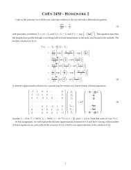
D/G-10 Service (Hydraulic End)e. Using petroleum jelly or grease to retain it, install the O-ring(65) and slide the housing (30) down over the shaft. Be surethe holes in the housing and the cylinder housing areproperly aligned.f. Install two assembly studes from Tool Kit, washers and nutson the threaded studs, but don’t tighten yet. You may wantto insert two or more bolts (4) into the unthreaded holes ofthe housing and cylinder housing to help align the parts.g. Alternately tighten the nuts of the assembly studs to evenlydraw the housing down to the cylinder housing. Be sure theO-ring (65) stays in place.Also, as you tighten the nuts keep checking the shaftalignment by turning the shaft (use the rotator in the WannerTool Kit). If the shaft begins to bind and become difficult toturn, back off the nuts and realign the shaft. When thehousing is tight against the cylinder housing, you should beable to turn the shaft smoothly.h. After the pump housing and cylinder housing are together,insert bolt (25) with lock washer (5) (at the 4 o’clock position)through the pump housing and into the cylinder housing.Repeat with a bolt (29) in the 10 o’clock position. Tightenevenly and then remove asembly studs.i. Turn the shaft again to check its alignment.5. Replace Shaft Sealsa. Apply a thin film of grease on the seal protector tool (part ofthe Wanner Tool Kit). Slide both seals onto the tool, with thespring side of the seals toward the open end of the tool.Apply a heavier coat of grease between the seals and pressthem together.b. Apply a coating of Loctite® High-Performance Pipe SealantWith Teflon®, or a comparable product, to the outer surfaceof both seals and the inside surface of the opening in thepump housing where the seals will rest.c. Apply a light film of grease to the drive shaft. Slide the sealprotector tool (with the two seals) over the end of the shaft.d. Slide the seal inserter tool (from the Wanner Tool Kit) overthe seal protector tool, and press the seals completely intoplace. Tap the tool with a soft mallet to firmly seat the seals.6. Adjust CamShaft Endplaya. Remove the three set screws (22) from the cylinder casting(24), and clean them.b. Insert the centerbolt (1) into the hole in the center of thecylinder casting. Turn it in to move the bearing adjustingplate (61) and cup tight against the bearing cone.c. Back out the centerbolt two full turns, then turn it back inagain until it is tight against the adjusting plate (61).d. Back out the centerbolt exactly 1/4 of a turn.e. With a plastic mallet (or a regular mallet and wooden board)to prevent damage to the shaft, rap the end of the shaft 3 or4 times. This will provide about 0.006 in. (0.15 mm) endplayin the shaft.f. Apply removable threadlocker to the threads of the threecleaned set screws (22).Screw the three set screws (22) into the cylinder castinguntil they contact the bearing adjusting plate (61).g. Remove the centerbolt (1).7. Install PlungersNOTE: If the plungers (21) have been removed from thevalve plungers (54), do not reuse them. Install new onesinstead.a. Rotate the pump shaft so the piston is at the top-dead-centerposition.b. Place a plunger on the exposed screw end of the plungerguide tool from the Wanner Tool Kit. The larger-diameterside of the plunger should face the tool.c. Screw the guide (with the plunger) into the valve plunger(54) until tight.d. Hold the single bottom handle of the guide, and turn thedouble top handle to force the plunger to seat on the valveplunger. This is a press-fit – when installed, the plungershould be tight against the shoulder of the valve plunger.NOTE: Do not remove the plunger guide until thediaphragm is installed (see below).e. Install the diaphragm as outlined below, then repeat theprocedure for the other two plungers and diaphragms.8. Reinstall Diaphragmsa. With the plunger guide tool still screwed into the valveplunger (54), pull the valve plunger up until the cross-holesin the valve plunger are exposed.b. Insert a diaphragm Allen wrench (from the Wanner Tool Kit),through the top hole — to hold the plunger (21) away fromthe cylinder casting, and to keep the valve plunger fromturning when the diaphragm is being installed.c. Place the diaphragm (20) onto the plunger (21), ridge-sideout.d. Center the diaphragm follower (19) on the diaphragm.e. Place the O-ring (18) onto the follower screw (17).f. Apply a small amount of threadlocker to the threads of thefollower screw.g. Insert the follower screw (with O-ring) through the diaphragmfollower (19) and diaphragm (20), and screw it into the valveplunger (54).h. Hold the plunger holder, and torque the follower screw to18 in.-lbs (2.0 N-m).i. Repeat the above procedure for the plungers anddiaphragms of the other two cylinders.j. Fill the reservoir with fresh oil and prime the pump, asoutlined in the Fluid-End Service Section.9. Reassemble Pump HeadReassemble the pump head as outlined in the Fluid-EndService Section.17 D10-991-2400 5/1/04