HYDRA CELL Manuale Uso e Manutenzione ... - Asco Pompe Srl
HYDRA CELL Manuale Uso e Manutenzione ... - Asco Pompe Srl
HYDRA CELL Manuale Uso e Manutenzione ... - Asco Pompe Srl
- No tags were found...

You also want an ePaper? Increase the reach of your titles
YUMPU automatically turns print PDFs into web optimized ePapers that Google loves.
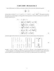
D/G-10 Service (Fluid End)2. Inspect Valves (10-15, 39)*NOTE: For non-metallic slurry duty pumps, see the insertto this manual for fluid valve service (Step 2), then proceedto Step 3 in this manual for remaining service steps.The three inlet and three outlet valve assemblies are identical(but face in opposite directions). Inspect each valve as follows:a. Check the spring retainer (15), and replace if worn.Note: if your pump has either abrasive duty valveassemblies or a non-metallic pump head there will be aplastic dampening washer (39) at the bottom of eachseat. Inspect each one for wear or cracks and replace ifnecessary.b. Check the valve spring (13). If it is shorter than a new spring,replace it (don’t just stretch the old spring).c. Check the valve poppet (12). If worn excessively, replace it.NOTE: If your pump has plastic spring retainers, thereis a tetra seal (flat O-ring, 14) between the retainer (15)and valve seat (11).d. Remove the valve seat (11). A seat remover is included inthe Wanner Tool Kit. Inspect the valve seat for wear, andreplace it if necessary.e. Reinstall the valve assemblies:• Clean the valve ports and shoulders with emery cloth,and lubricate them with lubricating gel or petroleum jelly.• Install the O-ring (10) on the valve seat (11).• Inlet (3 center valves). Insert the spring retainer (15)into the valve plate, then insert the spring, valve, andvalve seat (13,12,11).If the pump has plastic springretainers, a flat O-ring (14) goes between the retainerand seat. Insert dampening washer (39) if included inyour valve assembly.• Outlet (3 outer valves). Insert dampening washer (39)if included in your valve assembly.Insert the valve seat,valve, and spring, then the retainer. If the pump hasplastic retainers, install the flat O-ring between theretainer and seat. If the pump has metal spring retainersin the outlet valves, position them so a leg does not pointtoward the center of the pump (refer to the illustrationbelow).WRONG: Retainerleg pointing towardcenter of pump.Installing Valve RetainersInto Valve Plate3. Inspect and ReplaceDiaphragms (20)If necessary to service the diaphragms, remove the two socketheadcap screws (41) that secure the valve plate (16) to thecylinder casting (24). Inspect the valve plate in the same manneras you did the manifold.a. Lift the diaphragm by one edge, and turn the pump shaftuntil the diaphragm pulls up. This will expose machinedcross-holes in the plunger shaft behind the diaphragm.b. Insert an Allen wrench through one of the holes, to hold thediaphragm up. The proper size tool is included in the WannerTool Kit.c. Remove the screw (17), O-ring (18), and follower (19) inthe center of the diaphragm.d. Remove the diaphragm, and inspect it carefully. A ruptureddiaphragm generally indicates a pumping system problem,and replacing only the diaphragm will not solve the largerproblem. Inspect the diaphragm for the following:• Half-moon marks. Usually caused by cavitation of thepump (refer to the “Troubleshooting” section).• Concentric circular marks. Usually caused bycavitation of the pump (refer to the “Troubleshooting”section).• Small puncture. Usually caused by a sharp foreignobject in the fluid, or by an ice particle.• Diaphragm pulled away from the center screw or fromthe cylinder sides. Usually caused by fluid being frozenin the pump, or by overpressurization of the pump.• Diaphragm becoming stiff and losing flexibility. Usuallycaused by pumping a fluid that is incompatible with thediaphragm material.• Slice in ridge of diaphragm. Occurs when a Vitondiaphragm is operated at cold temperatures.• Diaphragm edge chewed away. Usually caused byoverpressurizing the system.e. Inspect the plunger (21) for any rough surfaces or edges.Do not remove the plunger from the plunger shaft. Smooththe surfaces and edges as necessary with emery cloth or afine file.CAUTION: If a diaphragm has ruptured and foreignmaterial or water has entered the oil reservoir, do notoperate the pump. Check all diaphragms, then flush thereservoir completely (as outlined below) and refill it withfresh oil. Never let the pump stand with foreign materialor water in the reservoir, or with the reservoir empty.f. Install a new diaphragm (or reinstall the old one, asappropriate), ridge side out.g. Clean the screw (17) and remove any oil from it. Applymedium-strength threadlocker to the screw. Reinstall thescrew and follower (19), and a new O-ring (18). Tighten to18 in.-lbs (2.0 N-m).h. Repeat the above inspection procedure (and replacement,if necessary) with the other two diaphragms.RIGHT12 D10-991-2400 5/1/04