4" Dredge Instructions - Keene Engineering
4" Dredge Instructions - Keene Engineering
4" Dredge Instructions - Keene Engineering
- No tags were found...

You also want an ePaper? Increase the reach of your titles
YUMPU automatically turns print PDFs into web optimized ePapers that Google loves.
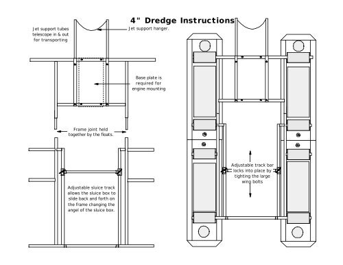
Jet support tubestelescope in & outfor transporting4" <strong>Dredge</strong> <strong>Instructions</strong>Jet support hanger.Base plate isrequired forengine mountingFrame joint heldtogether by the floats.Adjustable sluice trackallows the sluice box toslide back and forth onthe frame changing theangel of the sluice box.Adjustable track barlocks into place bytighting the largewing bolts
Floats are held in place bythe use of 8 push pinsTake the time to make sure that all hose clampsare tight and the couplings are all snug beforeattempting to operate the dredge.The 2" pressure hose assembly screwsonto the pump with a 2" pressure hosecoupler and the other end is connected tothe power jet with a hose clamp.The foot valve and hose assemblyclamps onto the black pump intakeon the pump.
Stage #2Secondary recoveryof coarse goldPrimary classifier screenSecondary classifier screenJet Flareline up carpet with the first riffleAdjustable flow control separatorsheet and carpet should be pulledout as far as possible to start.Stage #3Allows fine material to enter lower section &protects it from high velocity water, providingsuper fine recovery of gold and black sandStage #1Recovers 90% of allvisible gold in theprimary recovery rifflesThree Stage Sluice <strong>Instructions</strong>The 3 stage sluice box requires more water than a normal sluice box to operate correctly. We recommend that theengine be ran at least 2/3rds. throttle or higher. If the engine operates too slow the riffles may become overloaded and aloss of fine gold will occur. The Adjustable flow control separator plate should be pulled out as far as possible toallow maximum flow into the 3rd. stage riffle area. If the Third Stage Riffle appears to be running too clean you canmove the separator plate inward decreasing the water flow allowing more material to accumulate into the riffle section.Side view of 3 stage sluice box2nd stage RiffleSecondary classifierPunch plate1st stage rifflePrimary recovery classifierwoven wireJet flareAluminum separator plate3rd stage riffleStandard Ribbed CarpetWire meshStandard Ribbed CarpetMiners MossBlack Rubber ribbed mattingSluice Box Tilt A d j u s t m e n tMove the sluice Box forward to increase or backward to decrease the angle. The proper sluice box angle adjustment can aff e c tthe recovery of values. If the sluice does not have enough angle the sluice box will "load up" causing the riffle openings to fill withunwanted excess material. Too much angle will cause the material to flow too fast, resulting in loss of values, evidenced by ther i ffles running too clean. If the sluice box is working properly, approximately one third of the riffle should be visible after pumpingclean water for a minute or so. Aloss of values can also occur if the ratio of solid content to water is too heavy. The solid contentshould not exceed 1 part material to two parts water. Anormal sluice box tilt is approximately 3/4” inch to the running foot.Example: Afour foot sluice box should have approximately 3 inches of tilt.First Stage:Cleaning the 3 Stage Sluice BoxA . Position the suction tip away from any material so it is sucking only water. Operate the engine at approximatly 2/3rds. throttlespeed for a several minutes to wash out any excess gravel that has accumulated in the riffle section.B . Turn the engine off or lower the engine speed to a slow idle. Remove primary and secondary classifier screens and riff l e .Remove the carpets and aluminum plate and wash the concentrates into a bucket or tub. Note: the primary riffle or 1st stage canbe cleaned separately without cleaning the entire sluice box. We recommend that the primary riffle be cleaned only once or twicea day. The balance of the sluice should be cleaned every few days, depending on the type of conditions encountered.2nd Stage:A . Unlatch the top 2nd. stage riffle and pivot back towards the jet flare. Roll the carpet up and wash out in a bucket or tub.3rd. Stage.A. Lift the adjustable flow control separator sheet up on it side and rinse the concentrates in to the lower third stage sluice.B. Remove the 3rd stage lower riffle and screen. Splash water on the riffle and screen to rinse any concentrates onto the carpet.Roll up the carpet and wash out the concentrates.Note: many of the above clean up procedures can also be done with the engine idling, however it will require a second person tohold a tub at the end of the sluice.
GENERAL OPERATING INSTRUCTIONSTHE FOLLOWING INFORMATION SHOULD ENABLE YOU TO UNDERSTAND THEBASIC THEORY OF OPERATION OF A PORTABLE DREDGE.For more complete understanding on this subject, we recommend you read any one of a variety of books availablethrough the <strong>Keene</strong> Library of Books, such as The Gold Miners Handbook, Dredging for Gold or Advanced DredgingTechniques. The vacuum on a portable dredge is created by a "venturi principal". A volume of water is pumped througha tapered orifice (jet), by a special designed water pump. A high velocity jet stream is created within the jet tube producinga powerful vacuum. As indicated in the diagram gravel is dredged into the suction hose and is delivered to the sluicejet flare. As a slurry of water and gravel enters the jet flare and is spread evenly over a classifier screen. The smaller andheavier particles drop below the classifier screen into an area of less velocity, allowing a slower and more selective classificationof values. Often values are recovered and easily observed before they even enter the riffle section. The lighternon bearing values and larger aggregate are returned back into the water. The riffles, or gold traps in the sluice box arebest described as "Hungarian Riffles". This type of riffle has proven to be the most efficient gold recovery system. Asmaterial flows over the riffles, a vortex, or eddy current is formed between each riffle opening. This force allows the heaviermaterial to settle out of suspension and the lighter, non value bearing material to be washed away. This continuousself cleaning principal allows a dredge to be operated for prolonged periods of time. Normal conditions require a sluicebox to be cleaned only once or twice a day.PRIMING THE PUMPBefore starting the engine, the pump must be fully primed. This means the pump must be full of water and all airremoved. All jetting pumps provided with our dredges have a mechanical water pump seal. Without the presence ofwater in the pump, friction could cause a seal to overheat and require replacement. Priming the pump on some of thesmaller models is accomplished by thrusting the foot valve back and forth under the surface of the water in a reciprocatingmotion. This will pump water into the foot valve assembly and into the pump. A pump is fully primed when water isobserved flowing out of the discharge end of the pump. It may sometimes become necessary to hold the dischargehose above the level of the pump to complete the priming operation. The larger dredges that have a rigid foot valve, areeasily primed by removing the cap provided on the foot valve and filling, until water overflows. Caution must be exercisedto prevent sand from entering the foot valve or intake portion of the pump. Excess amounts of sand could damage thewater pump seal, or pump impeller. It is recommended that the intake portion of the foot valve be placed in a sand freeenvironment underwater, such as a small bucket or pan.PRIMING THE SUCTION HOSEPriming the suction hose need not be of concern in most dredging operations, but is important to understand the principal.When the tip of the suction hose is taken out of the water during operation air will enter the suction system andcause the suction power to cease temporarily, until submerged again. The suction will commence as soon as the air haspassed through the system. It is important to ensure that no air leaks occur in the suction system.SUCTION SYSTEM OBSTRUCTIONSThe suction system can become jammed while dredging. This can be caused by dredging an excess of sand, causingthe suction hose to load up, or a rock that has become stuck in the suction system. Rock jams generally occur in the jet,or just before entry into the jet. This can easily be cleared by removed by flipping the rubber damper back over the jetflare and thrusting the probe rod down through the jet flare and jet in an effort to strike the obstructed area. It may occasionallybe necessary to remove the suction hose to remove an obstruction. If this is not successful. it may be necessaryto locate the blockage in the transparent hose and dislodge it by a striking the obstruction, taking care not to damage thehose.SOLID CONTENTCare must be exercised to prevent dredging excess amounts of sand. A solid to water balance must be maintained. Thesolid content being dredged should never exceed 10%. If a suction tip is buried in the sand and not metered properly thesolid content could cause the suction hose to become overloaded with solids and suction will cease, this will also causethe sluice box to become overloaded with solid content, resulting in a loss of values.SLUICE BOX ADJUSTMENTMost models have a slight adjustment to raise or lower the sluice box. The proper sluice box adjustment can effect therecovery of values. If the sluice does not have enough angle, the sluice box will "load up" causing the riffle openings tofill with unwanted excess material. Too much angle will cause the material to flow too fast, resulting in loss of values, evidencedby the riffles running too clean. The optimum adjustment of a properly working sluice box is evident by only aportion of the riffle is visible while operating. A loss of values can also occur if the solid content of the suction discharge istoo heavy in solid content. Remember, the solid content should not exceed 10 %. A normal sluice box tilt is approximately3/4” inch to the running foot. Afour foot sluice box should have an approximate tilt of 3"CLEANING THE SLUICE BOXBefore attempting to clean the sluice box, it should be allowed to run with only water for a few minutes in order to wash
out any excess gravels that have accumulated. Either turn engine off, or let run with a slow idle, then remove the classifierscreen and replace the wing nut to prevent losing it. Unsnap the riffle latches, fold the riffle tray up, and let rest againstthe jet flare, taking care not to let it drop back into place while cleaning. This could result in a potential injury! Place awide tray, bucket or large gold pan at the end of the sluice, then carefully roll up the riffle matting and wash into the containerat the end of the sluice. Rinse any excess gravel that remains in the sluice into container. All material must beremoved before replacing the riffle matting, riffle tray and classifier screen.ENGINE SPEEDMost small engines are throttle controlled. The speed of the engine can be controlled with the use of a lever. Althoughthe rated horsepower is achieved on most small engines at 3600 R.P.M., it may not be necessary to operate the dredgeat full speed. Lower speeds conserve engine life and fuel economy. Be sure to read all instructions and especially theengine instructions that are provided with each unit. ENGINES ARE NOT SHIPPED FROM THE FACTORY CONTAIN-ING OIL. OIL MUST ADDED PRIOR TO USE! ENGINES OPERATED WITHOUT SUFFICIENT OIL S U P P LY W I L LINVALIDATE ENGINE WARRANTEE!TROUBLE SHOOTING[A] IF SUCTION DECLINES1. Check the suction device for an obstruction. An obstruction can be removed by probing the obstructed area with theprovided probe rod. I may be necessary to check the suction hose for a visible obstruction. This can be remedied byeither back flushing the system or dislodging the obstruction with a gentle blow.2. Check the pump for loss of prime or blockage. The foot valve may be too close to the surface of the water and air mayenter the intake of the pump via a small whirlpool. The pump intake or foot valve screen may be plugged with leaves ormoss, restricting flow into the intake of the pump. Check and tighten all clamps to prevent an air leak.[B] IF PRIMING THE PUMP BECOMES DIFFICULT1. Check all clamps for an air leak.2. It may be necessary to check the foot valve for a small leak. This is accomplished by removing the foot valve assemblyfrom the pump and blowing air into the hose portion of the assembly and listening for an air escape. It may be necessaryto remove the hose and check the rubber valve for an evidence of a leak, or for a small obstruction preventing thevalve from sealing.3. If a water pump seal is either defective or damaged, a leak will be evident on the inside portion of the pump aroundthe drive shaft. Often a new pump will leak slightly, until the seal and gasket has become fully seated. This is a commonoccurrence in most new pumps.INTAKE HOSEPUMPSUCTIONNOZZLEFOOT VALVEPRESSUREHOSERIFFLESSLUICE BOXPOWER JETSUCTION HOSE
KEENE ENGINEERING20201 Bahama Street Chatsworth California 91311Tel. (818)-993-0411 Fax. (818)-993-0447E-mail: keene@jetlink.netWeb site www.keeneengineering.comINSTALLATION & REPLACEMENT OF A PUMP SEAL, MARLEX PUMPCOUPLER & A COMPRESSOR DRIVE ASSEMBLYThe water pump seal must be replaced if water is observed leaking between the engine and pumpadapter or around the engine shaft,. To replace a seal or to install a compressor drive assembly (engineshaft pulley and drive belt), the pump must first be removed from the engine.INSTRUCTIONS TO REMOVE THE PUMP FROM THE ENGINE:Note: If the pump has been in use for a year or more, we suggest that you apply a penetrant such as"WD-40" to the engine shaft threads and allow it to penetrate the threads of the engine shaft. Saturate for24 hours before attempting to remove the impeller from the engine shaft!1. Remove the four housing bolts and remove the pump housing. If the housing does not pull off easily,gently pry it off with a screwdriver. Inspect the housing gasket and replace if necessary.2. The impeller is directly mounted to the engine shaft and will unscrew in a counter clockwise direction.Before attempting to remove the impeller the engine shaft must be locked in a fixed position to preventit from turning. A simple way of locking the shaft is to insert a pointed tool such as a screwdriver or an awlthrough one of the many holes in the starter assembly and turning the engine over until the tool is firmlylocked in place by the starter housing cover.IMPORTANT: Always disconnect the spark plug wire before attempting any repairs or service on yourpump or engine. Once the engine shaft is locked into position, there are two methods that can be usedto remove the impeller.Method #1. Use a block of wood, such as a 2x4 and place one corner of it into one of the impeller vaneson the left side of the impeller and strike the block of wood sharply with a hammer. This should loosenthe impeller and enable it to be unscrewed in a counter clock-wise direction.Method #2. If the above is not successful, use a thin breaker bar or a heavy duty screw driver. Insert theblade into one of the impeller vanes towards the left side and try to unscrew the impeller by applying adownward pressure. If this still does not work carefully strike the end of the bar with a hammer until theimpeller loosens from the shaft. If this still does not work, strike gently with a hammer. This method maycause a chip in the vane of the impeller. Depending on the size break of the corner of the impeller, it mayor may not have adverse effects on the performance of the pump. So be careful!SEAL REMOVAL AND INSTALLATION:1. All of our pumps use a two piece seal assembly, with the exception of some older models (P-50and P-60). One half of the seal located in the backside of the impeller is called the "seat", or ceramicportion. The other side of the seal is shrouded in a brass encasement, encasing a hardened material thatrests against the ceramic portion of the seal. Always replace both sides of the seal. Remove the ceramicportion with a sharp object similar to a screwdriver and press the new seat into place by hand. Alwaysinspect the seal to note that it is not cracked. Always place the smooth surface of the seal to the outside.
2. Remove the pump adapter from the engine and press the brass portion of the seal towards theoutside from the back of the adapter. If it cannot be pressed out easily, place a screwdriver handle onthe seal and gently tap it out. When replacing, it is suggested that a small amount of silicone sealant beplaced on the brass portion that fits into the adapter to ensure that it will not leak. Be careful not to get anysealant on the face of the seal. Position the seal in the center of the hole and press gently by hand intothe cavity as far as possible. Use a screwdriver or a blunt instrument and tap the seal gently around theedge of the seal in a circular motion until the seal is firmly fitted into place. Wipe off seal facing with a cleancloth before reassembling.3. After both sides of the seals is installed, replace the pump adapter onto the engine and carefullytighten. Thread the impeller onto the engine shaft until the impeller is hand tight. Install the housing anduse care not to over tighten the bolts to avoid stripping the threads as they are a soft alloy aluminum.HOW TO INSTALL THE HOSE ADAPTOR PUMP INTAKE COUPLER: (For all models except theP-50 and P-300 Series).The tolerance of the Hose Adapter is critical for proper pump performance. The hose Adapter shouldbe installed as close as possible to the intake portion of the impeller. Center the adapter into the housingopening and press in by hand to locate it into place and place a wooden block against the outside of theadapter and gently tap until the adapter is firmly seated against the face of the impeller. Pull the starterrope until the engine turns. When the coupler is properly seated, the engine should be somewhatdifficult to turn over, making sure that the adapter is against the face of the impeller.COMPRESSOR DRIVE INSTALLATION:To install the shaft pulley and belt for a compressor adaptation, the pump must be completely removedfrom the engine. For larger engines to include the 8 HP through 18 HP engines, slide the pulley to theback of the engine shaft and tighten the set screw. To install the engine pulley on smaller engines toinclude the 3HP to 5HP Engines, the furnished bushing should be pressed onto the pulley at the factoryto ensure proper alignment and spacing. If you choose to install it yourself, this can be accomplished byplacing the pulley on a flat surface, center the bushing in the hole of the pulley and gently drive it throughby tapping it with a hammer taking care not to damage the bushing. The bushing should be pressed ordriven through the pulley, in a flush position to the other side of the pulley. It should not extend thoughthe other side. Then install the V Belt before placing the pulley and bushing over the engine shaft. Afterthe pump is installed and secured, mount the compressor and compressor pulley. Install the V Belt tocompressor and make sure that the alignment is correct. You can compensate for some misalignment byadjusting the compressor pulley on the compressor shaft. Tighten firmly the set screw and all bolt andcheck for any misalignment before starting.
1112CENTRIFUGAL PUMP ASSEMBLYSTANDARD 5/8" TREADED SHAFT ENGINE10THREADEDENGINESHAFT1 2 3 4 5 6 7 8 9P100 and P180 PUMPSINSTALLATION NOTES:The rotation of all is counter-clockwise. Water must be contained within the pump while it is running. Do not run thepump dry, as it will damage the pump seal and may lead to the need to replace the seal. To ensure continuousperformance, it is always a good idea to carry a spare seal, in case you need to replace it. For maximum pumpperformance, use only <strong>Keene</strong> <strong>Engineering</strong> foot valves.INSTALLATION INSTRUCTIONS:1. Before installing the mounting plate (7) to the engine, the spring portion of the water pump seal (5) must be installed.Place this portion of the seal into the center of the mounting plate, with the use of a light hammer and or bluntinstrument and a seal setting tool. Tap the perimeter metal portion of the seal to set the seal into position. Care must betaken to avoid contact with the carbon portion of the seal. A small amount of Silicone Rubber Cement placed in thissection will insure a water tight seal. Insert the FOURmounting bolts (6) into the mounting plate (7). Tighten the boltsevenly so as to prevent mis-alignment.2. Fit "O" Ring gasket (OR1) into "O" slot on the front face of the mounting plate, making sure that it is properlyseated. Place the ceramic portion of the water pump seal (4) into the center of the impeller (3) firmly, using the heal ofyour hand to insure a proper fit. The ceramic surface of the seal must be facing outwards. Thread the impeller onto theengine shaft by turning it gently in a clockwise rotation, taking care to avoid damage to the threads on the impeller.3. Attach the outer housing (2) to the mounting plate, using the housing bolts (8) and washers (8A). Tighten thehousing bolts evenly to ensure proper tension and alignment. Extreme care must be taken to prevent over tightening ofthe bolts. Too much torque will damage the threads in the outer housing.P100P180ITEM DESCRIPTION QUANTITY PART NO. PART NO.1 HOSE ADAPTER 1 HA1 HA12 OUTER HOUSING 1 101 1813 IMPELLAR 1 102 1824 PUMP SEAL (CERAMIC SEAL) 1 WPS2(PT.1) WPS2(PT.1)5 PUMP SEAL (SPRING & CASING) 1 WPS2(PT.2) WPS2(PT.2)6 MOUNTING PLATE BOLT 3 MB MB7 MOUNTING(BACK) PLATE 1 105 1058 HOUSING BOLT 4 HB HB8A HOUSING BOLT WASHERS 4 HW HW9 SHAFT BUSHING 1 SB SB9A COMPRESSOR DRIVE 1 P3 P310 "O" RING(GASKET) 1 104 10411 FLUSHER ADAPTER CAP 1 FAC FAC12 FLUSHER ADAPTER 1 FA FA13 FAC RUBBER SEAL(INSIDE CAP) 1 FACS FACS
Introductionto Hookah DivingThere are two air supply systemsthat are used for underwaterdiving activities. One system,known as Self ContainedUnderwater Breathing Apparatus(SCUBA), involves the use of highpressure metal tanks which areworn on the diver's back whilediving. The equipment used inSCUBA diving is quite technical innature, and SCUBA gear should notworld topside.There are many times when anunderwater diver does not need when the engine or motor thatthe total freedom that is afforded powers the compressor ceases toby the SCUBA air system, particularlyoperate. This makes for a trulyin cases in which the diver economical air system, which willbe used by persons who have not is submerged in a limited area for quickly pay for itself when comparedbecome a certified diver involvingexpensive, specialized instruction.long periods of time.For these applications, the to the cost of refilling aSCUBA tanks every hour or so.Without a certification card"Hookah" (Surface Air Supply) The only operating cost for aindicating completion of such acourse, you cannot purchase compressedwas invented. The The Hookah air Hookah system is fuel, since thesystem uses no high pressure airvast majority of Hookah compres-air.tanks of the type worn on a diver's sor units are gasoline powered.Of course, the SCUBA air systemback. Instead, it uses a small airIt is not uncommon to get twohas its advantages as well. compressor A which is located at the hours diving time on a single gal-diver using SCUBA gear is liter-surface. It is commonly poweredlon of gas, which shows just howally "an entity unto himself,"since he carries his life giving airsupply on his back at all times. Hecan go anywhere he chooses, completelyfree of any ties with theby a portable gasoline engine orelectric motor, and the air isdelivered to the diver via a floatingair hose. With the Hookahsystem, the diver has an unlimitedand nearly "cost free" air supplywhich will only stop flowing1
economical the Hookah air system recommended that at least a 40can be.micron filter be included toMost Hookah divers will haveremove any solid particles thata partner working "topside" as may a occur. This type of Hookahsafety man, and he can refill the compressors contains sealedengine's gas tank as it starts get-bearingting low. This will enable the lubrication which can rather than oil forcontami-diver to stay submerged so long as nate the air supply. Most compressorsutilize an “oil bathhe desires.lubrication system which willTHE AIR COMPRESSOR contaminate the air supply.The Hookah air system begins Hookah compressors operateat the diver's air compressor.Hookah compressors are small,Typical Hookah Air CompressorModel T-80at a relatively low pressure. Themaximum pressure availablefrom the higher capacity modelslightweight, and of simple design. greater depths. If a diver isThey are commonly constructed of working at depths of 33 feet oran aluminum alloy, and utilize less, a he will need only 30 to 40allow for increased exertion.If a diver is breathing at anormal rate (light exertion), thepressure relief valve will occasionally"pop off" and shoot out aburst of air. This is normal, as itprevents excess buildup of pressurein the compressor head. If adiver is breathing heavily and isunder physical exertion, he willbe demanding all of the volume andpressure that the compressor candeliver. In this case, the pressurerelief valve will rarely, if everdischarge excess pressure oris about 125 pounds per square "pop off."inch. The higher the operating The type of Hookah compressorthat is required for a givenpressure, the lower the air output.Consistently high operating diving operation is dependent uponthe extent of underwater physicalexertion, the depth, and the numberof divers that are connected tothe system. A single diver underlight exertion at shallow depthspressures (unless the unitspecifically designed for highpressure use) will shorten thelife of the compressor by anoticeable degree. Conversely,the LOWER the operating pres-will require a relatively smallsure, the greater the air output, air output that is measured inand the longer the compressor "cubic feet per minute," orlife. A compressor should not be "CFM". The same diver underoperated at high pressures unless heavy exertion will require additionalair at a slightly highera diver intends to be submerged atpressure and volume.If more than one diver is connectedto an air system, or if divingat greater than normal pounds per square inch for opti-depths,rubber diaphragm as the means ofair displacement. There are also mum operation of his regulator. more air volume at higher pressurescompressors that use a "piston"arrangement to displace air andmay be required.Most Hookah compressorshave a built in "pressure reliefthese types generally deliver valve" which prevents excessive THE AIR RESERVE TANKmore air at higher pressures than pressure from building up in the The next major component inthe diaphragm models. The moving compressor head when the diver the Hookah air system is theparts inside a Hookah compressor is only making a small "demand" reserve tank. This very importantare lubricated with Teflon for the on the compressor. This valve is piece of equipment performs fourlife of the unit, and need no addi-usualltional preset at the factory at vital functions:lubrication; to do so mayactually damage the compressor.approximately 50 p.s.i., whichwill give the average diver atThe reserve tank operates asan air ``reservoir," that suppliesThe air that is delivered by this shallow depths enough air to a constant volume of air at alltype of Hookah compressor is operate his regulator while leavingtimes. If, you are diving underenough pressure left over to heavy exertion and demandingpure, oil free air. It is howevera2
Air Reserve Tank Model RT-1greater amount of air, the largevolume of air in the reserve tankwill supply the reserve airrequired. If you were breathingTypical air system for one diver, including air hose, reserve tank,regulator, harness, and connector hose to compressordirectly from compressor itself,your rate of inhalation mightan even flow of air.food grade vinyl wrapped with aactually surpass the air volumeAnd finally, the most importantfunction of all. The reserve covered with a heavy duty PVCnylon webbing reinforcement andprovided by the compressor, andyou would not get a sufficienttank will contain enough pressurizedair to give the diver a couplehose is designed to prevent kink-abrasion resistant wall. Hookahamount of air.The reserve tank functions asof minutes breathing time, should ing and collapsing that could preventthe flow of air being shut offa cooling and condensation vessel.his compressor, or engine failureFew divers realize it, but the airrun out of fuel. Equipment breakdownis not a pleasant thing to colored a bright yellow or orange,A quality Hookah hose will beemerging from a Hookah compressoris quite hot, and can actuallyreach temperatures as highconsider while working underwater,but is always a possibility. will also float, so that any excessfor a high degree of visibility. Itas 190 degrees.In the event of an engine failure hose not actually being used willAs the air enters the thewithout a reserve tank in the system,a diver could experience an away from the diver, reducingfloat on the surface, completelyreserve tank, it will expand andthecool. This expansion process willimmediate loss of air that could possibility of entanglements onalso condense most of the watercontained in the compressed air.lead to desperation and panic. Anyexperienced diver will tell you,the bottom. For example, if youare diving in ten feet of water butHookah compressors, because ofthat panic is the leading cause are of using a thirty foot length oftheir small size, do not have thedrowning incidents.capability to remove the moisturefrom the air and hence, theydeliver air with an appreciablemoisture content. The expansionHookah air system is the air hose. impart any "flavoring" to the air,process in the reserve tank allowsHookah air hose is made of a spe-ancial vinyl plastic construction, is OSHA” requirements.should meet “ FDA andthe water to condense, ensuringthat the diver breaths less mois-resistant to the effects of oil,gasoline and sunlight that existsin the environment.ture in the air.The reserve tank also suppressessurges from the compressoror any temporarydecrease in running speed. Often aTHE AIR HOSEThe next component in theConventional rubber hoseshould never be used for diving,because it will gradually deteriorateand become toxic. Hookahthe compressor's engine will rununeven due to moisture in thehose commonly has an insidegasoline. The reserve tank candiameter of 3/8ths. of an inch. Itcompensate for this by deliveringis constructed of an inner liner of3air hose, the excess twenty feetwill float on the surface, completelyaway from you.A quality Hookah air will notTHE REGULATORThe regulator is an oral respirationdevice that is worn in thedivers mouth. The regulator regulatesthe amount of air that isreceived by the diver each timehe inhales. Because the diversnose is covered by his face mask,air must be inhaled through the
2. The regulator intake hose thatTypical Hookah Air Regulator andattaches to the check valve preventsany pulling motion from theHarness Model HR-2 repair station will also have thenecessary test gauges, etc., to regulator while working underwater.For example; if a diverdivers mouth .make certain the adaptation hasThere are two types of divingbeen effective.were moving around underwaterregulators, those designed for A Hookah regulator is entirely and inadvertently came to the endSCUBA use and those designed for different from a SCUBA regulator. of the air hose, the harness wouldHookah applications. A SCUBA It consists of a "second stage" absorb the shock and the regulatorregulator is designed for use with only, which is fed directly from and would not be jerked from theSCUBA a air tank, and delivers the output of the reserve tank via diver's mouth.maximum efficiency when operatedat a pressure exceeding 100assemblies of the type that arethe air hose. There are valve nop.s.i. They require a "first stage" used with SCUBA tanks. Hookahvalve assembly, attached to the regulators employ a "tilt," orSCUBA tank. The function of thefirst stage is to reduce theextremely high pressure of theair in the SCUBA tank fromapproximately 2,250 p.s.i. toapproximately 180 p.s.i. ThisSCUBA regulator, but who wishester of the diver's back when theto use it for Hookah applications, harness is worn. The back platemust take his regulator to a competentholds a "check valve," which actsdive shop or repair station as a "junction point" for the airand get the regulator convertedover for low pressure use; hehose and the regulator. Since theair hose terminates at the diver'sshould not attempt to do it himself. back, it prevents potentialThe conversion can be made byinstalling a set of low tensionentanglements around the diver'sbody.springs which will give maximumefficiency when operated at lowHookah pressures. A dive shop or"pin" valve, which delivers a fullair flow to the diver at a pressureas low as 30 p.s.i. This type of3. The check valve that is foundon the back plate performs thethird very vital function. It actsas a "safety gate" by shutting downthe air system, allowing the air totravel in only in one direction.regulator is specifically designedShould a burst or leak occur in thefor use with low pressure Hookah air line somewhere between thecompressors. Hookah regulators, output of the compressor and thepressure then goes to the "secondas are all modern regulators, areinput of the check valve, it couldstage," which is the part that isof the single hose, "demand" type. prevent a vacuum occurring inworn in the diver's mouth. The A "demand" regulator works on the a mouthpiece of the regulator orsecond stage of a SCUBA regulator relatively low volume of air, cause a diver to breath in a largehas a spring loaded "downstream" since it only has to deliver air asamount of water that could causevalve which delivers the correct the diver breathes, or "demands" panic. “ Never, ever, dive withouta harness and check valve!"amount of air to the diver when it..driven by an air pressure rangingfrom 100 to 250 p.s.i. THE HARNESSINCIDENTAL ACCESSORIES,A prospective Hookah diver A regulator should not be used HOSES, HINTS, PRECAUmustrealize that SCUBA regulatorsCANNOT be used for Hookah conjunction with a "chest har-One accessory hose item youfor Hookah diving unless it is TIONS: inapplications without special modifications.A typical Hookah com-principle functions:for routing the air output fromness." The harness serves three will need is a short length of hosepressor operates in an averagethe compressor to the input of thepressure range of 30 to 50 p.s.i., 1. It keeps the air hose from gettingin the diver's way when he is that is needed depends upon thereserve tank. The type of hosewhich is not enough pressure todrive the spring loaded downstreamvalve of a SCUBAworking underwater. The harness compressor you are using.regula-has a "back plate" which is auto-Diaphragmatically a positioned over the cen-the 30 to 50 p.s.i. range use models that operate intor. A diver who already owns a4
simple hose connector that ismade of hookah air hose.The high pressure, high volumepiston compressors that arecapable of delivering pressure of100 p.s.i., require a connectormade of special certified "heatresistant steam" hose, due to thefact that these models discharge exhaust at a sufficient height should or you experience anyair at higher temperatures. distance to avoid intake of enginemechanical failure on a divingWhen setting up a Hookah airexhaust gas. If this gas is inhaledsystem, you will frequently needeven in small quantities for shorttrip. It is a good idea to carryalong some spare parts for youran array of metal fittings. For periods, it can cause severe air compressor, and the necessarytools to make repairs.use around water, you should use headaches and possibly result instainless steel or brass fittings sickness. In larger quantities it All of the basic "rules of theonly. This is especially importantcan kill you, so please be careful! deep" that apply to SCUBA divingwhen diving in salt water. If you are using Hookah also apply to Hookah diving asequipment around salt water, be well.Fittings made of ferrous metalwill rust or corrode when usedin, or near a water environment.If your Hookah compressor ispowered by a gasoline engine,make every effort to ensure thatthe engine exhaust (which containsdeadly carbon monoxidegas), is always placed DOWN-WIND from the compressor. Thiswill help prevent exhaust frombeing accidentally pulled into theand compressor unit.Always install a long extensionon the intake of your compressorto avoid the possibility ofcontamination of Carbon MonoxideGas from the engine exhaust system.The air intake of a compressormust tower over the enginesure to rinse off all your componentswith freshwater afterwards.This includes your regulator,diving mask, harness,metal fittings, and air hose (flushit out on the inside as well as outside).A salt water environmentwill quickly corrode aluminumparts such as: Hookah compressorsand gasoline engines. It isattached to the air system at alladvisable to keep all metal componentstimes. If you were to experiencefreshly painted and underwater problems, your "div-compressor's air inlet. Always cleaned to avoid excess corrosion. ing partner" should be availableuse a “snorkel” extension on any If you are using a gasoline to come to your immediate assistance.compressor that can elevate theintake of the air supply awaypowered compressor always shutof the engine before attempting tofrom engine exhaust contaminates.refuel. Do not attempt to refillthe engine's gas tank while theEven though no formalinstruction is required toNever use a gasoline poweredengine is still running, as this use Hookah equipment, wecompressor in confined areas,such as underneath piers, inwill increase the possibility ofspilling gasoline onto a hotstrongly recommend that alldivers should take aclose, narrow grottos, etc. This engine, which could result in a “CERTIFIED SCUBA” coursewill prevent the exhaust gases potential fire or cause an explo-aing your local county or div-from dissipating into the atmos-sionpheresupply store.safely. Also, never dive inan area where there is little ventilationor air movement. Takespecial precautions when divingA diver should always surfaceand shut off the engine first priorto refueling and allow time for theengine to cool down. Always use aYou should also read books onthe subject of underwater divingsafety and study them thoroughly.in areas where the air is funnel for refilling the gas tank, This will further familiarize youextremely still, as dead airspaces, or poor ventilation cancause exhaust gases to linger inor a special spillproof gas containerto prevent spillage.Every Hookah diver shouldwith the "rules of the deep."the immediate area of the engine understand the basic rudiments of5engine and compressor maintenance,and should always keep hisequipment in top condition. If youtake proper care of your equipment,it will give you many yearsof trouble free service. Knowinghow to work on your own equipmentwill also come in handy,UNDER NO CIRCUMSTANCESSHOULD YOU DIVE ALONE.!Always Hookah dive with apartner who owns his own regulator,harness, and air hose.Make sure that his or herequipment as well as yours is
WARNING CARBON MONOXIDE GASIf you're considering diving with a "Hookah Compressor" , It is most important that you become aware ofPotential Danger associated with exhaust emissions. We place a caution label on the engine, warning of dangerousengine fumes and also illustrate further warning in " Introduction to Hookah Diving" and Safety inGold Dredging that is issued with the purchase of all diving equipment.WHAT IS CARBON MONOXIDE GAS?Carbon Monoxide is an invisible odorless gas which gives no warning of its presence. It is the product ofthe incomplete burning of any material such as ; Oil Gasoline, Wood, Coal, etc. that contains carbon.WHAT IS THE EFFECT OF CARBON MONOXIDE EXPOSURE?Carbon Monoxide deprives the blood of its ability to carry oxygen throughout; the body. When CarbonMonoxide is inhaled , it chemically combines with hemoglobin, the oxygen carrier in the blood. Even ifthere is plenty of oxygen in the air, hemoglobin combines much more readily with Carbon Monoxide thanwith oxygen. As the oxygen level of the blood is reduced, the heart must pump faster in an effort to supplysufficient amounts of oxygen to the brain and other parts of the body. When the brain does not receiveenough oxygen, symptoms of headache, dizziness and mental confusion occur. Further exposure to the gascauses lack of coordination, weakness and nausea. The final effect of excessive exposure are convulsions,coma and death.Needless to say, we cannot emphasize strongly enough that caution must be excersized. Never dive alone,never dive in an enclosed area, or in an area where good ventilation is not eminent such as; under piers, narrowgrottos, under heavily overgrown brush or trees or in any area where a good breeze does not occur.Always make an effort to position your air unit to allow the prevailing breeze to carry any exhaust emissionsaway from the air intake of the compressor.Remember, Carbon Monoxide is the product of incomplete burning of gasoline and oil, so it most importantto keep your unit properly running and clean. Never allow gasoline to overfill or spill anywhere near engineand compressor.THE SAFETY AIR SNORKEL DOES NOT ELIMINATE CARBON MONOXIDE GAS, IT ONLY AIDSIN THE REDUCTION OF FUMES. ALL THE SAFETY CAUTIONS MUST BE OBSERVED !SNAP FITREMOVE AIR FILTER FROM THEAIR COMPRESSOR AND INSTALLIN THE TOP OF THE AIR SNORKEL1/4-20 X 2"BOLTALUMINUM SNORKELSUPPORTS#10-24 X 2.5"BOLTALUMINUMSPACERSNORKEL SLIDES INSIDETHE COMPRESSOR INTAKE1/4" NYLON NUTAND WASHER#10 NUTSSTABILIZINGBRACKET#10-24 X 1/5PHILLIP PAN HEAD6