Instruction Manual GP 3500 - Minelab
Instruction Manual GP 3500 - Minelab
Instruction Manual GP 3500 - Minelab

Create successful ePaper yourself
Turn your PDF publications into a flip-book with our unique Google optimized e-Paper software.
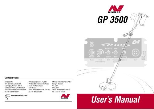
MINELAB<strong>GP</strong> <strong>3500</strong>Contact Details:<strong>Minelab</strong> USA871 Grier Drive, Suite B1Las Vegas, Nevada 89119UNITED STATES OF AMERICAemail: minelab@minelabusa.comtel: +1-702-891 8809<strong>Minelab</strong> Electronics Pty LtdPO Box 537 Torrensville PlazaSouth Australia 5031AUSTRALIAemail: minelab@minelab.com.autel: +61-8-8238 0888<strong>Minelab</strong> International LimitedLaragh, BandonCo. CorkIRELANDemail: minelab@minelab.ietel: +353-23 52101www.minelab.comMINELABUser’s <strong>Manual</strong>
l <strong>GP</strong> <strong>3500</strong> l page ithe <strong>Minelab</strong><strong>GP</strong> <strong>3500</strong>An IMPORTANT MESSAGE from MINELABWe ask YOU, as a responsible detector operator, to take all due care regarding the environment.<strong>Minelab</strong> cannot stress enough the importance of being responsible when recovering targets.BACKFILL EVERY HOLE YOU DIG.If care and consideration is taken, during and after the removal of targets, especially withrespect to the back filling of holes, this should ensure the continued access to areas forprospecting and treasure hunting. This will also ensure that the pristine condition of ourbeautiful bushland, forests and dry land areas is maintained with a minimum of damage.<strong>Minelab</strong> is working with you towards preserving our natural environment so that the benefitsof gold prospecting and treasure hunting can continue to be enjoyed in the years to come.Every prospector and treasure hunter around the world and the staff of <strong>Minelab</strong> thankyou for your continued efforts towards protecting the environment.<strong>Minelab</strong> wishes to thank you for purchasing our most advanced gold detector ever, andare confident the <strong>GP</strong> <strong>3500</strong> will lead you to success in your quest for gold and treasure.<strong>GP</strong> <strong>3500</strong>www.minelab.com<strong>GP</strong> <strong>3500</strong>page<strong>GP</strong>i<strong>3500</strong>
page iv l contact lcontactl 1 introduction l page 1introducing the <strong>Minelab</strong> <strong>GP</strong> <strong>3500</strong>Contact <strong>Minelab</strong><strong>Minelab</strong> is always interested in your opinions so if you have any questions or comments regardingthe <strong>GP</strong> <strong>3500</strong> or any other <strong>Minelab</strong> product, please feel free to contact us via your local Authorized<strong>Minelab</strong> dealer, or write to us:<strong>Minelab</strong> Electronics Pty LtdPO Box 537Torrensville PlazaSouth Australia 5031Australiaemail:ho@minelab.com.autel: + 61 8 8238 0888<strong>Minelab</strong> USA871 Grier DriveSuite B-1; Las VegasNevada 89120United States of Americaemail:minelab@minelabusa.comtel: + 1 702 891 8809<strong>Minelab</strong> International LimitedIDA Industrial EstateLaragh; BandonCo. CorkIrelandemail:minelab@minelab.ietel: + 353 23 52101The <strong>Minelab</strong> <strong>GP</strong> <strong>3500</strong> utilises “Dual Voltage Technology” (DVT),which assists accurate ground balance and increases sensitivityby overcoming the potential problem of super-saturatedelectro-magnetic fields in heavily mineralized ground.Here are some features of the <strong>GP</strong> <strong>3500</strong>:• NEW Quick-Trak push button located in the handlefor fast and accurate ground balancing;• NEW <strong>Manual</strong> Tune control for more preciseinterference control & frequency band selection.• NEW Operator select 3-Speed Ground Tracking• Improved "Smart Point" diagnostic plug• Separation of Level Adjust functions• Easy Adjust Bow Knuckle and hand strapLike its predecessor, the <strong>GP</strong> 3000, the <strong>GP</strong> <strong>3500</strong>can handle heavily mineralized and salty groundconditions with greater ease than previous detectors,which effectively opens up NEW detecting areas.The new Low-Noise circuitry found in the <strong>GP</strong> <strong>3500</strong>results in a smoother threshold, enhancing yourability to hear faint signals caused by small anddeep targets.Visit our site on the World Wide Web: http://www.minelab.com for the latestinformation on <strong>Minelab</strong> products and services.page iv<strong>GP</strong> <strong>3500</strong><strong>GP</strong> <strong>3500</strong>page<strong>GP</strong>1<strong>3500</strong>www.minelab.com
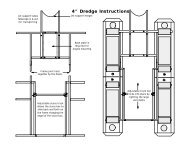
page 4 l 2 assembly lcomplete assembly instructionsYou will need to assemble the <strong>GP</strong> <strong>3500</strong> from all the various components, so wehave provided you with detailed assembly instructions.Attaching the coilcomplete assembly instructions – continuedAssembling the lower and upper shaft sectionsRefer Figure 2.2l 2 assembly l page 5Step 1. Slide the lower shaft (4) with coil attached into the end of the upper shaft (8), snapspring clip into place.Step 1. Check that the coil (1) has a skid plate (3) attached.Step 2. Take two teardrop washers (5) from the bag and install them into the indentationson the end of the lower fibreglass shaft (4).NOTE – The washers should always be full thickness and should be replacedregularly as they wear out and allow the coil to become loose.Attaching the handle and arm restStep 1. Slide the bow knuckle (22) onto the uppershaft (8) and slide it halfway down.Step 2. Slide the handle (9) onto theupper shaft (8) and slide down.Figure 2.3 - Attaching the armrestrefer also Figure 2.1Step 3. Push the lower fibreglass shaft (4) into the mounting brackets on the coil and ensurethat the spring clip at the rear of the fibreglass shaft, faces the rear of the coil.Step 4. Line up the holes in the coil with the pivot end of the fibreglass shaft (4). Push thenylon bolt through the holes and fit the nylon wing nut and tighten by hand.NOTE – Do not over tighten the nut as the coil housing may be crushed or damaged.Tear-drop Washers (5)Nylon Nut & Bolt (6)Step 3. Place the two armrest halves (11)on either side of the upper shaft (8)and ensure that the bolt holes arealigned.Step 4. Slide the two nylon bolts (12)Nylon Bolts (12)through the bolt holes and screw thenylon wing nuts (13) onto the bolts by acouple of turns.Armrest Parts (11) Nylon Nuts (13)Step 5. Attach the armrest straps (14) using the press studs on bothsides of the arm rest.Step 6. Push the armrest straps (14) through the slots in theneoprene armrest cover (15) and then push the cover overthe armrest (11).<strong>GP</strong> Series 1100 Coil (1)& Skid Plate (3)Step 7.Position your arm into the armrest and slide the handle to acomfortable position. Tighten the two screws in the base ofthe handle with a small screwdriver to hold the handle in position.Figure 2.2 – The coil pivot end of the lower fibreglass shaftTip: For the best balance, the rear of the armrest should be just in front of your elbow.page 4<strong>GP</strong> <strong>3500</strong><strong>GP</strong> <strong>3500</strong>page<strong>GP</strong>5<strong>3500</strong>www.minelab.com
page 6 l 2 assembly lcomplete assembly instructions – continuedAttaching the Control Box and achieving balanceStep 1. Position the ‘T-section" on top of the control box (10) into the armrest with thebattery plug at the rear. Tighten the nylon wing nuts by hand.Step 2.Step 3.Loop the Quick-Trak button cable from the handle, back along the shaft and plug itinto the Smart Point connection in the control box (10). (See page 33)Adjust the shaft length and coil angle for a comfortable position. The lowerfibreglass shaft can be set into position by locating the spring clip intothe holes provided in the upper shaft and hand tightening thelocking nut at the end of the shaft. The correct length of shaftfor your height, is at the point that the coil can beswung in front without you bending, dropping yourshoulder or work in a position that willbe uncomfortable.Handle withWrist Strap (9)Fitting and connecting the battery packStep 1. Fit the battery (17) into the backpack pouch (18).Step 2.l 2 assembly l page 7complete assembly instructions – continuedConnect the headphones (16) and the power cable (19) to the appropriate sockets inthe cap of the battery.Step 3. Put on the backpack (18).CAUTION – Use only the 6V battery supplied.Headphones (16) Power Cable to Detector (19)Bungy Cord (21)6Volt Battery (17)Figure 2.5The <strong>GP</strong> <strong>3500</strong> battery assemblyFigure 2.4 – Handle and bungy cordSecuring and connecting the coil cableNOTE – Always ensure that the control box is turned Off before connecting ordisconnecting the coil, to avoid damage to the detectors electronics.Step 1.Bow Knuckle (22)Wind the coil cable around the shaft and plug the coil connector intothe coil socket on the control box. Check that the cable is wound firmlyaround the shaft without strain, leave enough slack at the bottom of thecable near the coil to allow for adjusting the angle of the coil withoutplacing strain on the coil cable.Step 2. Fasten the cable into position using the Velcro straps provided (20).Step 4.Backpack Pouch (18)Ensure that the power switch on the control box is switched Off before pluggingthe power cable connector (19) into the socket on the controlbox. This cable connects the battery and headphones to the detector.Step 3.Secure the bungy cord through the bow knuckle (22). Slide the knuckle upor down the shaft (8) to find the balance point and tighten the wing-nut.HINT If the coil cable is able to move around, especially near the coil, it will be‘seen’ by the detector and cause random noises which may be confusing.page 6<strong>GP</strong> <strong>3500</strong><strong>GP</strong> <strong>3500</strong>page<strong>GP</strong>7<strong>3500</strong>www.minelab.com
page 8 l 2 assembly lcomplete assembly instructions – continuedAdjust for your own comfortStep 1. Adjust the bungy cord (21) from the knuckle (22) on the shaftto the correct length to take some of the weight when prospecting.Step 2.Step 3.TIP:Adjust the hand strap on the handle (9) for your own comfort.Adjust the rear harness strap on the battery bag so that the batterysits at a comfortable position on your back. The ideal position is whenthe weight of the battery counter balances the weight of the detector, andyou can still switch on the detector without putting excess strain on thebungy cord. Taking the time to adjust your detector properly is veryimportant for comfortable long term detecting.You may need to change the length of the bungy cord or the position of thebow knuckle when you change coils or detect on sloping ground.The Batteryl 3 batteries l page 9batteriesThe 6V rechargeable battery can provide enough power to operate the detector for14-15 hrs, when fully charged.The battery may be recharged at any time during the discharge cycle.It is very important to fully charge the battery before storage.Do not leave a battery fully discharged for longer than one day.CAUTION: Never use a 12V battery because this could damage the detector. This damageis not covered by warranty. The <strong>GP</strong> <strong>3500</strong> power supply is internally regulated and using anexternal regulated power supply is not necessary, and may damage your detector. If you wishto operate your detector at full power for longer, we would recommend that you own twobatteries and swap halfway through the day.Low battery indicationIf the battery level drops below the required power to give adequate function, a series of alarmsignal pulses are given at half second intervals.Charging the batteryStep 1Step 2Turn the detector Off before disconnecting the battery.Disconnect the battery cable from the detector and connect to the appropriatecharger.Battery chargersTwo types of battery chargers (Mains and 12V Vehicle Charger) are supplied.ImportantWhen charging, the battery must be kept in an upright position.page 8<strong>GP</strong> <strong>3500</strong><strong>GP</strong> <strong>3500</strong>page<strong>GP</strong>9<strong>3500</strong>www.minelab.com
page 10 l 3 batteries lbatteries – continuedMains battery chargerThe mains battery charger will charge the battery from local mains (AC) power outlets.easy referencel 4 controls and operation l page 11detector soundsStep 1.Step 2.Step 3.Connect the mains charger to a mains outlet.Connect charger to the battery using the power cable.Switch the mains outlet on.The charger will recharge a completely flat battery in approximately 24 hours. Partiallydischarged batteries will require a shorter period to recharge. Allow approximately 1.5 to2 hours charging for each hour the battery was in use. The flashing rate of the chargerLED will decrease as the battery gains charge.Vehicle battery chargerThe vehicle battery charger will charge the battery from the cigarette lighter socket of mostmotor vehicles.Step 1.Step 2.Step 3.Connect the charger to the cigarette lighter socket and turn the ignition switchto Accessories.Connect the detector battery to the charger using the power cable.This supplies 12V power to the cigarette lighter socket. This voltage is converted bythe charger to charge the detector battery. A red LED indicator will flash while thebattery is charging. When the battery is flat the LED may flash fast enough so as toappear constantly on. As the battery gains charge, the LED will flash at a slower rate.Leave the battery to charge for approx. 10 hours using this charger.If the battery voltage of your vehicle drops below 11V, the charger will stop operating.Therefore the battery charger should not flatten the vehicle battery. Check that yourvehicle battery is in good condition before camping in remote areas and run yourengine above idle speed for at least 30 minutes each day to keep your vehicle batterycharged.CAUTION – The Vehicle Battery Charger is designed for use with vehicles, whichhave a negative earth electrical system. Most cars manufactured after 1970 should havenegative earth electrical system. Connecting the charger to a vehicle with a positive earthsystem will cause the fuse in the cigarette lighter plug to blow and the LED indicator willnot light. If you need to replace the fuse located in the cigarette lighter plug, you will needto use a 3ag/10amp fuse.DETECTOR SOUNDS - ExplanationsIn the course of operating your detector, there will be various noises and sounds that you mayhear. Here is an explanation of some of these sounds.Threshold and ToneThis is the background sound produced by the detector. The level is set using the Thresholdcontrol. The tone of the threshold is set using the Tone control.Target SignalThis is the abrupt change of the tone and volume of the threshold sound when a target isdetected.• The maximum level is set by the Volume control.• The amount of tone variation is set by the Signal control.• If the tone falls first and then rises, as the coil is passed over a target, this generallyindicates a large target.• If the tone rises first and then falls, as the coil is passed over a target, this generallyindicates a small target.Ground NoiseIrregular noises that are difficult or impossible to pinpoint when moving the coil over theground. Ground noise is caused by the changing chemistry or 'mineralization' of the ground.Maintaining an accurate ground balance will greatly reduce this effect.Tune IndicationAn initial beep sounds, then while the detector is testing the range of bands for the moststable, the threshold may become more quiet or chattery. Once selection is complete, threesharp ‘beeps’ are given.Low Battery IndicationIf the battery level drops below the desired power to give adequate function,a series of alarm signal pulses are given at half second intervals.page 10<strong>GP</strong> <strong>3500</strong><strong>GP</strong> <strong>3500</strong><strong>GP</strong> <strong>3500</strong>page 11www.minelab.com
page 12 l 4 controls and operation l easy referenceQuick start instructions controls and operation – continuedStep 1. Set the Coil switch to Double D.Step 2.Step 3.Step 4.Set Soil switch to N (Normal).Set Balance switch to Fixed.Set Iron Discriminate knob to All Metals.l 4 controls and operation – rear l page 13controls and operation rear controlsTRY OUR WAY FIRST!Take the time to read this manual thoroughly. The <strong>GP</strong> <strong>3500</strong> introduces new functions andchanges the way some others that you may have been familiar with, now work. Howeverexperienced you are at using a metal detector, it is important that you read this chapter tounderstand these new controls and how to use the <strong>GP</strong> <strong>3500</strong> to its full capacity.Step 5.Step 6.Step 7.Step 8.Step 9.Step 10.Set Boost to N (Normal) for general detecting.Set Volume to maximum and Signal to 2 o’clock.Turn Power Switch on and adjust the Threshold control so that a faint sound isheard through the headphones.Adjust the Tone to suit your hearing.To tune out interference, hold the detector at waist height with the shafthorizontal and the coil vertical.Slowly move the coil around your body through a half-circle until the noise fromthe interference is loudest.Rear Control FunctionsThere are two control panels: the rear panel and the front panel.Step 11.Step 12.Step 13.Step 14.Step 15.Step 16.Place the detector on the ground in that position and push the Tune buttononce to start the tuning function. Leave the detector undisturbed untilfinished sequence.Tuning takes approximately 60 seconds. A series of 3 beeps will indicate that theoptimum frequency has been selected.Do not move the detector during thetuning processKeep the All Metal / Disc control in the All Metal position.Put the Balance switch to Fixed and while moving the coil up and down holddown the Quick-Trak push button in the handle. This puts it into Tracking ModeOnce Ground Balance has been achieved, release the push button.The detector is now ready for operation.Figure 4.1Rear Panelpage 12<strong>GP</strong> <strong>3500</strong><strong>GP</strong> <strong>3500</strong><strong>GP</strong> <strong>3500</strong>page 13www.minelab.com
page 14 l 4 controls and operation – rear lrear controls – continuedFigure 4.2Threshold - On/OffcontrolNOTE – Small targets or large deep targets may not produce a distinct target signal, but may causeonly a small variation in the threshold level. If the threshold level is set too high or too low, these verysmall variations may be missed. Experiment with known targets to assist in setting all controls to suityour hearing.Figure 4.3Threshold control – too highThreshold - On/OffNOTE – Always switch the detector Off before connecting ordisconnecting the coil or battery pack and when not in use.This switch turns the power from the battery to the detector, On and Off.It is also used to set the background “hum” of the detector. This “hum”is known as the Threshold.Operating <strong>Instruction</strong>s: The Threshold control should be set at apoint where the threshold is just audible and stable. This level shouldnot be at a level where prolonged use may become irritating. Ideally itshould be a smooth, gentle hum.Figure 4.4Threshold control – too lowFigure 4.5Threshold control – just rightFigure 4.6Volume controlFigure 4.7Maximum volumel 4 controls and operation – rear l page 15rear controls – continuedVolumeSets a maximum loudness of the target signal obtained from a largetarget. Refer to Figures 4.7 - 4.9. The dotted line in these figuresrepresents the level of volume set by the volume control.Operating <strong>Instruction</strong>s:• If the Volume is set to maximum (fully clockwise), the target signalis unaltered and proportional to the target size and depth(see Figure 4.7).• If the Volume control is turned down to half way, the target signalis unaltered for a small target, but is limited for a bigger target(see Figure 4.8).• If the Volume were to be turned down close to minimum, itpotentially will limit all signals to such a degree that most targetswill be lost (see Figure 4.9).Figure 4.8Mid-range volumeFigure 4.9Minimum volumeIn Figures 4.3 - 4.5, the dotted line represents the level at which theaudio output becomes audible; signals cannot be heard if they are belowthe dotted line.If the threshold level is set too high then small variations in audio signalmight not be discernible above the threshold level and the threshold willdrown out very soft signals. An example of this would be to hear awhisper within a crowded noisy room.If the threshold level is set too low there is no audible background signaland small target signals will not go above the threshold of audibility.NOTE –Threshold should be reset after adjusting theVolume level.Volume should be set so that target signals are clear and easy to hearbut loud signals are not uncomfortable to your hearing.Set the Volume by passing the coil across a large target and adjustingvolume to a comfortable level. Now test a very small target at this level.page 14<strong>GP</strong> <strong>3500</strong><strong>GP</strong> <strong>3500</strong><strong>GP</strong> <strong>3500</strong>page 15www.minelab.com
page 16 l 4 controls and operation – rear lrear controls – continuedFigure 4.10Tone controlToneAdjusts the tone of the threshold. The user may set this to the preferredtone, e.g. the tone at which the operator’s hearing is most sensitive.Some people will find that their hearing is best in a particular range ofpitch, setting the tone control to this pitch will mean that the operator islistening more acutely, and probably more comfortably.At minimum position, threshold gives a low tone. Turning clockwiseincreases the tone to a higher pitch.Operating <strong>Instruction</strong>s: Adjust the Tone control until the thresholdis at a comfortable tone for your hearing then test it on a couple of smalltargets. Adjust until you obtain the best signal response.HINT Setting Tone to a high pitch may be more fatiguing, but is moresuitable for identifying soft target signals.Figure 4.11Signal controll 4 controls and operation – rear l page 17rear controls – continuedSignal AudioHuman hearing is sensitive to changes in tone, so the operator is morelikely to hear a target signal when both the volume and the tone changerather than volume alone. Interpretation of the target signals involvesunderstanding the difference between the rising and falling tone andvolume of the threshold in response to different targets.The Signal control gives the operator the ability to choose between atarget signal that has a large variance of tone, or one which has lessvariation. High variance can give the operator more signal definition tointerpret, however in highly mineralized ground this high variance ofsignal may cause confusion and make the detector appear noisy so alower setting may be preferred.The Signal Audio control adjusts the pitch response of the target signal.As a target is located, the target signal will change tone. For smalltargets it will often drop to a deeper pitch then rise to a higher pitch.The range of variation is controlled using the Signal knob.Figure 4.12Reduced pitch varianceFigure 4.13Increased pitch varianceOperating <strong>Instruction</strong>s:In Figures 4.12 and 4.13 the curving line represents the high/low pitchresponse to a target. The dotted line represents the threshold tone.• At minimum position the high/low pitch variance of the target signalis reduced.(see fig. 4.12) So target signals are more monotone.• At maximum position the high/low pitch variance of the target signalis increased.(see fig 4.13) So that there is a large variance betweenhigh and low pitch of the target signal.page 16<strong>GP</strong> <strong>3500</strong><strong>GP</strong> <strong>3500</strong><strong>GP</strong> <strong>3500</strong>page 17www.minelab.com
page 18 l 4 controls and operation – rear lrear controls – continuedBoost (Shallow/N/Deep)Boost switch selects the type of processing and filtering applied tothe detector signals to enhance different target signals in differentcircumstances.l 4 controls and operation – rear l page 19Soil (Sensitive/Normal/Salt)rear controls – continuedThis switch is used to optimise the detector for different soil conditionsand targets by changing the signal processing.Figure 4.14Boost switch• N (Normal) mode may be used for general detecting conditions.This does not boost any signals.• Shallow mode boosts signals from small targets close to thesurface.This makes faint target signals easier to hear. This setting may alsoboost some ground noise, therefore Shallow is better suited for'quiet' ground conditions or for pinpointing tiny targets.• Deep may be used when searching for large targets at greater depthin 'noisy' ground. Random soil signals are smoothed, making smallchanges in the audio signal from large deep targets easier to hear.This may mask some signals from very small targets near thesurface.Selection of the more suitable position should be after considering boththe expected target size/depth and ground conditions.NOTE – When Boost is changed, Threshold may also need to beadjusted. External amplifiers may be used in addition to the Boostswitch, provided that they have loudness limiters built in. Thisprevents loud signals becoming unpleasant or dangerous to theuser's hearing.Figure 4.15Soil switch(Normal/Sensitive/Salt)Operating <strong>Instruction</strong>s:• N (Normal) mode may be used in all areas, including areas withhighly mineralized soil. This position has very good sensitivity toa wide range of nugget sizes and is the most versatile of the threepositions.• Sensitive mode may be used when searching for small nuggets,especially in areas with highly mineralized soil. The extra stabilityallows the coil to be used closer to the ground in areas of excessiveground noise. Sensitive may not work well if the ground is salty.This setting may reduce the depth at which large nuggets arelikely to be found.• Salt mode may be used in areas containing a high salt content,be they neutral or heavily mineralized. In highly mineralizedareas without salt, this setting may be less sensitive to smallnuggets than Normal or Sensitive settings, but the difference tolarge targets is marginalpage 18<strong>GP</strong> <strong>3500</strong><strong>GP</strong> <strong>3500</strong><strong>GP</strong> <strong>3500</strong>page 19www.minelab.com
page 20 l 4 controls and operation – front lfront controlsFront Control FunctionsSmartPointFig 4.17Smart Pointl 4 controls and operation – front l page 21front controls – continuedSmart Point - A quality initiative from <strong>Minelab</strong> ElectronicsThe Smart Point is an intuitive new feature of the <strong>GP</strong> <strong>3500</strong>. It serves twofunctions1) It is the connection point for the Quick-Trak push button toconnect with the control box circuitry; (see page 33 - Quick-Trakreset button for more details.2) It is a diagnostic/test port that ensures that your detector isoperating at peak performance before it leaves the factory.Smart Point also allows Authorized <strong>Minelab</strong> Service Engineersworldwide to service and test your machine to ensure consistentand maximum performance at all times. For service informationplease contact your local Authorized Dealer. (See p45)Figure 4.16Front Panelpage 20<strong>GP</strong> <strong>3500</strong><strong>GP</strong> <strong>3500</strong><strong>GP</strong> <strong>3500</strong>page 21www.minelab.com
page 22 l 4 controls and operation – front lfront controls – continuedFigure 4.18All Metal / IronDiscriminate switchAll Metal/Iron DiscriminateDiscrimination is the ability of a detector to distinguish betweendifferent types of metal objects and to assist the user in identifyinga target.The <strong>GP</strong> <strong>3500</strong> is capable of rejecting many iron objects while stilldetecting non-ferrous metals. The ability of the detector to discriminateferrous targets means that, while detecting in littered goldfields, muchof the iron rubbish may be ignored, with a high probability that valuabletargets will not be missed.When the control is turned off ( anti-clockwise), you will detect inAll Metal and will detect any type of metal. This is the preferred settingfor most operators and the use of discrimination is restricted for use inhigh trash areas.In All Metal mode, it will give varying volume and pitch signals but thisinformation does not indicate the type of metal in the object.By rotating the control clockwise past the ‘click’, you switch into theferrous discrimination mode. In Disc, a strong response from a ferrous(iron) object will cause the threshold and target signal to be momentarily'blanked' or silenced.NOTE – If the target response is too weak for accuratediscrimination, the detector will give a normal target signaluntil you dig closer to the target and the signal strength improves.As the control is turned further clockwise, the operator it able toinfluence the recognition of a target being ferrous or non-ferrous metal.Discrimination - continuedFigure 4.19 – Discrimination levelsl 4 controls and operation – front l page 23Iron discrimination with the <strong>GP</strong> <strong>3500</strong> is the silencing or ‘blanking’ of the threshold and targetsignal, which occurs when the detector determines a target is comprised of ferrous metal.There is no discrimination when Iron Discrimination is set to All Metal.When a target has been located using Disc, the coil should be rapidly passed back and forthover the target centre several times. Remember to set Ground Balance to Fixed for this andkeep the sweep across the target at a level height and as close to the ground as possible.You should always test the target from at least two directions (90 o to each other)so that the detector sees the target from different profiles.When detecting a piece of iron, a normal target signal will start to be heard until thetarget signal becomes strong enough for the detector to determine that the objectis ferrous. At this point, the signal will 'blank'.front controls – continuedTIP: For large very deep targets, the hole being dug may not be wide enough for the coil tomove sideways across the target. Therefore the discrimination will not be accurate.page 22<strong>GP</strong> <strong>3500</strong>www.minelab.com<strong>GP</strong> <strong>3500</strong>page 23
page 24 l 4 controls and operation – front lfront controls – continuedDiscrimination - continuedThe strength of the target response required for discrimination to occur may be altered byrotating the control knob.There is usually some merging of characteristics between targets, which are clearly ferrousand others that ‘may-be’ ferrous. Rotation of the control knob allows the operator to make afine adjustment in the determination of the ‘may-be’ signals.• (Fully anti-clockwise) – just past the ‘click’ turning discrimination on, will keep thediscrimination cautious and ‘may-be’ targets will respond with a normal non-ferroussignal and only definite ferrous targets give the blanking. (as per Figure 4.20).Figure 4.20A normal signal on anon-ferrous target.• (Fully clockwise) In this position, the control becomes a little less cautious and some‘may-be’ targets will be seen as ferrous and give a blanking signal (as per Figure 4.21).In this position some small non-ferrous targets eg: coated in ironstone, could bemistaken for ferrous.Discrimination - continuedl 4 controls and operation – front l page 25front controls – continuedKeeping the control anti-clockwise requires a slightly stronger signal before discriminationoccurs, rotating it clockwise means that discrimination will occur on a weaker target.Discrimination functions will only work with strong, positive target responses. Weakresponses will give normal 'all metal' type signals.HINT It is usually best to dig out all targets and only use the discriminationfunction in areas where a large amount of rubbish makes the digging of everythingimpractical.Discrimination will give the best results when used in combination with the specially designed<strong>GP</strong> Series Double-D coils and will not work correctly when using mono coils.NOTE – If Pinpointing a target prior to digging, best results will be from switching outof discrimination and into all metals.Selection of how far to turn the discrimination knob should be determined by how cautiousyou want to be and how much trash is in the area. If the area is heavily littered, you may wantto use a less cautious discrimination and have the knob in the 5.00 o’clock position. If there islittle trash in the area and most close to the surface you may prefer a more cautious positionof 9 – 12.00 o’clock.TIP: If you are on a known gold producing site or successful patch, it is best to dig up all targets.Figure 4.21Discrimination targetsignal on a ferroustargetpage 24<strong>GP</strong> <strong>3500</strong>www.minelab.com<strong>GP</strong> <strong>3500</strong><strong>GP</strong> <strong>3500</strong>page 25
page 26 l 4 controls and operation – front lfront controls – continuedCoil (Double-D/M/Cancel)l 4 controls and operation – front l page 27front controls – continuedFigure 4.22Coil switchThis control changes the sensitivity and search pattern of the coil to allowthe <strong>GP</strong> series of Double-D coils to become multi-versatile with differentcharacteristics to suit different environments. This is achieved by alteringthe pattern of transmit (TX) and receive (RX) fields of the coil and how thecontrol box interprets the response. Selection of different positions of thisswitch, changes the electromagnetic field of the coil, thus giving betterperformance in certain environments.• Double-D has the coil operate in a conventional Double D searchpattern and can be used in most areas of medium to very highmineralization, being the most able to cope with these conditions.It is also excellent for pinpointing targets as the response is strongestfrom the centre of the coil.• M (Mono) changes the way the coil transmits and receives its signaland may be used in most locations of low to medium mineralization,and for locating small nuggets with Soil switch set to Sensitive. Use ofMono will often increase the sensitivity of the detector but may also bea little more unstable in heavily mineralized ground. Pinpointing is notcentred in the middle of the coil, but to one side and may give acomplex signal when the target is very close to the coil.• Cancel changes the electromagnetic field of the coil so that it isparticularly stable in areas of electrical interference. This positionis ideal in areas where the operator wants to detect close to suburbiaor where the Tune function has difficulty selecting a quiet operationalfrequency (e.g.: near power lines, phone towers or under pooratmospheric conditions). Pinpoint in Cancel will again be to one sideof centre and signals may be complex if the target is close to the coil.This setting will limit sensitivity to deep targets.NOTE – Coils not specifically designed for the <strong>GP</strong> <strong>3500</strong> may behave erratically or beineffective in either M (Mono) or Cancel modes.<strong>Minelab</strong> Monoloop coils can be used on the <strong>GP</strong> <strong>3500</strong> with excellent results and we recommend theiruse in conjunction with the coil switch in the M (mono) mode. This allows the use of monoloop coilsin soils where prospectors previously had to revert to using Double D coils.In extreme mineralization, particularly heavy ironstone concentrations, you may experience a loudsignal spike when attempting to ground balance or while searching. The signal is random and verysharp and it is not characteristic of a normal target signal. To prevent it from occurring, keep yourcoil a few centimetres from the ground, or opt to use in Double D mode.IMPORTANTYou will need to re-ground balance every time you select a new position for the ‘Coil’ switch.page 26<strong>GP</strong> <strong>3500</strong>www.minelab.com<strong>GP</strong> <strong>3500</strong><strong>GP</strong> <strong>3500</strong>page 27
page 28 l 4 controls and operation lfront controls – continuedFigure 4.23Balance switch(Fixed/Tracking)Balance (Fixed/Tracking)The ground you’re searching in contains not only sand, but also manydifferent chemicals, minerals and salts. These extra materials are referredto as ground mineralization. This ground mineralization may often producea sound from the detector, known as ‘ground noise’.The <strong>GP</strong> <strong>3500</strong> has the ability to cancel out the effects of groundmineralization automatically. This minimises ground noise and retainsmaximum sensitivity to metal targets. Cancelling the effects of groundmineralization is referred to as 'ground balancing'. This ensures thattarget signals from objects, such as gold, are not confused with interferingground noise.The <strong>GP</strong> <strong>3500</strong> automatic ground balance continually adjusts to minimisethe effects of changing ground mineralization when balance is set toTracking. The <strong>GP</strong> <strong>3500</strong> may be operated with fixed ground balance orautomatic tracking ground balance.• When Balance is set to Fixed, the ground balance remains at thecurrent level. To re-balance, you just press the Quick-Trak push buttonwhich triggers a fast re-balance, then returns to Fixed to continuedetecting once this button is released.• When the ground is variable in mineral content requiring repeatedre-balancing, use Tracking as the detector continuously tests theground and makes changes to suit. (see Tracking Speed (p.32) formore information.)Ground Balancing Procedurel 4 controls and operation l page 29front controls – continued• Have the Fixed / Tracking switch in Fixed position• Move the coil up and down between 20mm and 100mm above the ground and, whilemoving the coil, press down the Quick-Trak push button in the handle• When the button is depressed, the Tracking program initiates its automatic groundbalance. This begins with a 5 second very fast ground balance, therefore it is importantto be moving the coil when the button is held down.• Keep moving the coil and keep the button depressed until all ground noise has stopped.• A persistent signal may indicate a target in the ground. If this occurs, then move the coilto a new location and repeat the procedure.When there is no longer a change in the threshold, while the coil is being raised andlowered, the detector is 'ground balanced'.• Release the Quick-Trak button and you can commence searching.You are now searching in Fixed position.Figure 4.24Ground BalancingProcedure20 – 100mmpage 28<strong>GP</strong> <strong>3500</strong><strong>GP</strong> <strong>3500</strong><strong>GP</strong> <strong>3500</strong>page 29www.minelab.com
page 30 l 4 controls and operation lfront controls – continuedOperating the <strong>GP</strong> <strong>3500</strong> in Fixed modeIn medium to quiet ground you will achieve better depth by operating your <strong>GP</strong> <strong>3500</strong> in theFixed position and using the Quick-Trak push button to re-balance when the ground changesand/or threshold becomes erratic. If the ground is highly mineralized or variable, thensearching in Tracking may be the preferred position.HINTS• Where possible always search in Fixed position for best depth and only use Tracking modein areas with excessive ground noise or rapidly changing ground.• When searching in Fixed position remember to re-balance periodically by pressing theQuick-Trak push button in the handle. This returns you to Fixed once the re-balance iscompleted and you release the button.• Always Pinpoint a potential target in Fixed.• If mineralization is excessive you may need to lift the coil off the ground by a cm or two,rather than keeping it right on the ground. This will help to reduce the effects of highground mineralization and let you hear more targets much easier.Operating the <strong>GP</strong> <strong>3500</strong> in Tracking modeIf the ground is highly mineralized or variable, search in Tracking mode.l 4 controls and operation l page 31front controls – continuedTo search in Tracking mode, switch the Fixed / Tracking switch on the control box intoTracking position.In this position the detector is continuously testing and re-balancing to compensate forchanges in the ground mineralization. There are three tracking speeds that you can searchin – Fast; Medium & Slow. – see next chapter for details.When searching in Tracking mode, the Quick-Trak push button takes you into Fixed modewhile the button is depressed.While in Tracking mode, the detector usually stops ground balancing when a target signal isdetected. However, a weak target response may not be recognised as a target if the coil isrepeatedly passed over it, and especially if operating in medium or fast tracking.For this reason the push button should be used to change to Fixed when pinpointing a target.When searching in Tracking, after locating a target or what you believe is a target, sweep thecoil around the target area, without passing across it, then hold in the Quick-Trak push buttonand pinpoint the target location.When releasing the button, the detector engages a short, fast tracking mode (indicated by abeep) then returns to the Tracking mode.TIP: When in tracking, you can use the push button as a ground balance reset.Simply raise and lower the coil a few centimeters, periodically to check theground balance, and if it not completely balanced just push and release thebutton while continuing the ground balance procedure.page 30<strong>GP</strong> <strong>3500</strong><strong>GP</strong> <strong>3500</strong><strong>GP</strong> <strong>3500</strong>page 31www.minelab.com
page 32 l 4 controls and operation lfront controls – continuedTrackingSpeedFigure 4.25TrackingspeedTracking SpeedIf searching in Tracking position, the operator can choose the speed thatis best suited to the area. In effect, this gives the operator 4 options tosearch in: Slow, Medium & Fast plus the 4th being Fixed Balance whichis the recommended position subject to variability of the ground mineralization.NOTE – The Tracking Speed switch does not effect the speed ofthe initial very fast auto-ground balance. This very fast initialground balance only lasts 5 seconds.If the area being detected has the mineralization changing too often forthe operator to search in Fixed position, the <strong>GP</strong> <strong>3500</strong> now allows theoperator to gradually step through from Slow auto-tracking, into Mediumspeed, then into Fast auto-tracking.Choosing the preferred speed of tracking should be simply steppingthrough the speeds from Slow through to Fast, with the preferred speedbeing the slowest speed which still keeps up with the variability of theground mineralization.l 4 controls and operation l page 33front controls – continuedQuick-Trak push buttonLocated in the handle of the <strong>GP</strong> <strong>3500</strong> is a push button which allows easy operation ofground balancing.The Quick-Trak push button has two functions depending on where the balance switch is seton the control box.If set to Fixed mode:If the Balance switch on the control box is set into the Fixed position, the detector willoperate with Fixed ground balance while detecting. When the ground mineralization changesand the operator needs to rebalance, by holding in the Quick-Trak push button, a 5 secondfast rebalance will occur. Once this has been completed, the push button can be releasedand the operator can continue detecting in Fixed mode.If set to Tracking mode:If the Balance switch on the control box is set to Tracking, the detector will continuouslytest and change ground balance to compensate for changes in the ground mineralization,(the speed of this is controlled by the Tracking speed switch). If a target signal is heard,the operator can change into Fixed mode by pressing and holding in the Quick-Trak pushbutton and while the the button is depressed, the detector will operate in Fixed mode forbetter pinpointing.On release of the button a short “beep” will be heardand a quick auto-ground balance is initiated prior toreturning to Tracking Mode.NOTE – The Quick-Trakpush button is onlyengaged and changingthe operating modewhile the button isdepressed. Once thebutton is relaxed, theBalance mode returnsto that selected onthe control box.Figure 4.26Quick-TrakPush Buttonpage 32<strong>GP</strong> <strong>3500</strong><strong>GP</strong> <strong>3500</strong><strong>GP</strong> <strong>3500</strong>page 33www.minelab.com
page 34 l 4 controls and operation lfront controls – continuedFigure 4.27Tune control & buttonTuneThe Tune function reduces the effects of electromagnetic interferencefrom sources such as power lines, radio transmitters and other metaldetectors. There are two controls allowing the operator the greatestflexibility.Auto push buttonPressing and releasing the Tune button starts automatic tuning. Thetuning process takes approx. 60 sec. and completion is indicated bythree sharp ‘beeps’. Once pressed, the <strong>GP</strong> <strong>3500</strong> scans through a widerange of search bands, testing each one for it’s susceptibility to outsideelectromagnetic waves in the same or similar bands that would causeinterference. On completing the search, it selects the most stable bandfor operating in the environment of operation.NOTE – Interference in some locations can change during thecourse of the day so you may need to re-tune from time to time tomaintain a smooth threshold as you move around the area.l 4 controls and operation l page 35front controls – continuedSet the Tune controlTuning should be done initially with the Coil switch in Double D or in M (Mono). If theinterference is still severe after completing the tuning operation, change the Coil switch toCancel and then re-tune the detector again.• Hold the detector at waist height and the coil vertical and slowly rotate through ahalf-circle (eg: from East to West, or from North to South).• Listen for any increase in interference as you move and when the interference is loudest,stop moving. Lay the detector on the ground, facing that position, and keeping thecoil vertical.• Press and release the Tune button.• The detector will then scan through the available range of transmission frequencies andautomatically select the frequency that results in the greatest reduction of noise fromelectromagnetic interference.• The end of the tuning process (which takes approx. 60 sec.) is announced by three beeps.NOTE – While the detector is selecting the preferred frequency, the coil must bekept motionless and clear of metal objects. If you move the coil or allow itto sense a metal target, the testing for the quietest band will be influenced.When tuning the detector in close proximity to other detectors, eachoperator needs to take turns tuning.Do not try to tune two detectors at one time.Figure 4.28The TuningProcesspage 34<strong>GP</strong> <strong>3500</strong>www.minelab.com<strong>GP</strong> <strong>3500</strong>page 35
page 36 l 4 controls and operation lfront controls – continuedAfter completing the Auto-tune, pick the detector up and with the coil rotated flat, into thesearch position, listen to see if it is stable. If a slight interference is still present, you can usethe manual control to fine tune the selected band.<strong>Manual</strong> Control<strong>Manual</strong> tuning can now be used by the operator to fine tune after the Auto tuning iscompleted. In areas where there is no interference being experienced, the <strong>Manual</strong> controlcan be used to select a personal search band.After completing the auto-tune, to fine tune the band, start turning the manual control quiteslowly in one direction, listening if the threshold becomes more stable or flaky. If this directiondoes not improve it, try the opposite direction. It is quite important that you turn the controlslowly to make very fine adjustments.If the interference persists after tuning, consider using the Coil switch set to Cancel positionand retune againHint: If detecting in a benign area of no interference, you may find that you can select a bandat one end of the scale or the other. Frequency bands in the counter-clockwise ‘start’ directionare lower frequency bands and higher frequency bands are toward the clockwise end. Turnthe control in the desired direction until the one beep or two beep signal is heard. Then usingslow turns in the reverse direction find a band which is stable. This will not make muchdifference but low frequency bands can give a little more depth to larger targets and highfrequency bands can give slightly more sensitivity to smaller targets close to the surface.Important: The manual control will signal when you have moved to the end of therange of frequency bands. When you arrive at the counter clockwise starting pointyou will hear a single beep to denote that this is the start, moving clockwise to theother end, you will hear two beeps to denote that it is the finish.Note – When turning the control rapidly to move to the desiredend you want, you will notice noise caused by the rapidmovement through the frequencies. This is normal andwill not be present when the control is turned slowly.There are 14 turns of the control from start to finish.Hints and techniques for better detecting and happy prospecting that will help you toutilise the power of your <strong>GP</strong> <strong>3500</strong>Some user tips:• Always ensure that the battery is at full charge so that your detector is working atoptimum performance. A worthwhile recommendation is to own a spare battery whichyou can swap half-way through the day thus making sure that you are always workingwith full power.• The battery should be worn in the backpack harness supplied. This places the batteryat the furthest practical distance from the coil.• Ensure that you do not set the shaft length too short. If the coil is too close to yourbody it might detect your pick, the battery or any other metal which you are carrying.Steel toe boots can obviously cause a problem with false signals. If false signals areoccurring as you sweep the coil, check that they are not produced by any metal that youare carrying. Move the coil closer, and then further away from your body, in order tocheck if the signals are coming from items such as your pick, boots or battery. If they are,you must increase the distance between the coil and these items.• Take the time to experiment with the different settings, to fully understand how to get themost out of your detector in different locations.Motion detectionThe <strong>GP</strong> <strong>3500</strong> is a 'motion' detector. Therefore the detector must be movingover a target to detect it.Parallel Sweeping Procedure• The coil should be swept over the ground ina side-to-side sweeping motion.• While sweeping the coil, it is important tokeep it parallel to, and at the same heightfrom, the ground at all times. Lightly skiddingthe coil across the ground can sometimeshelp in this, depending on mineralization.• Do not raise the coil at the ends of eachsweep as this will reduce the detection depthand may cause false signals.l 5 detecting l page 37detecting techniquesFigure 5.1 - Parallel Sweepingpage 36<strong>GP</strong> <strong>3500</strong>www.minelab.com<strong>GP</strong> <strong>3500</strong>page 37
page 38 l 5 detecting ldetecting techniques – continuedCovering the search area• As the user moves forward slowly, the search pattern should resemble a snaking path.• To ensure that productive ground is thoroughly searched, approach the area from3 different directions.Overlap each sweep• Each sweep of the coil should overlap the area covered by the previous sweep to ensurea full coverage of the area being searched.• Be aware of the search pattern of the coil being used and overlap sweeps to take thispattern into account. If using a Monoloop coil a tighter overlap is required to ensure thattargets at maximum depth are not overlooked.• See also Pinpointing Technique,page 41.l 5 detecting l page 39prospecting techniquesThe <strong>GP</strong> <strong>3500</strong> has superior ground balancing and it is possible to find quite largeobjects near the surface in well-worked areas where other detectors have been unableto cope with the high degree of mineralization and/or salt. Therefore the user shoulddig all target signals, even in previously detected areas.• Very sudden or large changes in the mineralization of an area may produce a signalfrom the detector. Usually this signal is very broad, and often only present in onedirection.• In some goldfields, a response may be received from a concentration of orange/reddishdyke material or clay. Remember, a metal target will get louder by getting the coil evencentimeters closer.• If detecting areas of extremely variable mineralization, detecting with the contours ratherthan across the changes will often stabilize the effect.• In some ground (particularly heavily mineralized areas) the operator may need to sweepthe coil 1 or 2 cm above the ground. This should give a more stable threshold and lessground noise.• With faint or indistinct signals that you are not sure of scrape a few centimetres off thesurface with your pick and see if the signal becomes clearer.Figure 5.2Search pathBig GOLD.Many detector operators have no trouble finding their share of small gold, but often aredisappointed at the lack of larger gold found at depth, even though they have dug up to1m for a soft drink can or a horse shoe. The reason is that big gold gives a muchdifferent response to the smaller shallower pieces. The signal is often quite broad, andthere is very little pitch variance. Just something to be aware of.Figure 5.3 Search area from3 directionsFor Maximum Gold Recovery• Keep the coil as close to the ground as possible.• Listen very carefully - this is more important than looking.• SLOW DOWN! Do not rush, take your time.• Have a positive mind set, and imagine a nugget at every next sweep!!• Remember that covering a small section of ground thouroughly will bemore productive than randomly searching a larger area.page 38<strong>GP</strong> <strong>3500</strong>www.minelab.com<strong>GP</strong> <strong>3500</strong><strong>GP</strong> <strong>3500</strong>page 39
page 40 l 5 detecting lidentifying target signalsMetallic targets will usually give a 'solid' sounding signal when the coil is sweptacross the object from any direction. A metallic target generally produces a short,sharp and mostly symmetrical signal. Ground noises usually give a broad unevensignal when the coil is swept from different directions and often may only give asignal from one direction and no signal on the return sweep.If you are not sure if the sound is ground noise or a target signal, you need to investigate.Scrape a shallow hole about 70-100mm deep over the suspected target. Sweep the coil overthe hole at the original ground level. Do not dip the coil into the hole. If the signal hasdecreased in volume or is less defined, it is probably ground noise.If the signal remains the same or becomes louder, it is likely a metallic target. If you are stillnot sure, make the hole deeper and repeat the process.A 'halo effect', which may be built up around a buried metal object, makes the object appearto be larger to the detector than it actually is. This will be reduced once the target is disturbedfrom its position in the ground (e.g. a small object, detected at a substantial depth, may bemore difficult to detect once disturbed from the ground and lying in the loose dirt. If the objectis reburied, the 'halo effect' will not be present).HINT Do not try to eliminate what might appear to be a faint, isolated ground noise bybalancing the detector on top because you may be 'balancing out' the target response froma deeply buried metallic target. Better to ground balance around the target without goingacross it, then switch to Fixed and try Pinpointing.l 5 detecting l page 41identifying target signals – continuedPinpointingTo find an object and reduce the size of the hole required to remove it from the ground, it isnecessary to pinpoint the exact location of the object.If a target is heard, first confirm it by setting an accurate ground balance and then pinpointing.To ground balance, if detecting in Fixed position, hold down the Quick-Trak push button andpass the coil around the area of the target, making sure that the target is not detected (keepthe coil well away from where the target is). Once completed relax the push button.If detecting in Tracking mode, move the coil slowly around the area of the target, keeping wellaway from the target itself, then hold down the Quick-Trak push button to go to Fixed and pinpointacross the target.When a target is detected, sweep the general area with the coil, taking note of where thestrongest signal is received.By shortening the length of the sweep it should be possible to draw an imaginary line in theground where the strongest signal is located.Line up the target at 90° from the initial direction and repeat the process. The object is locatedwhere the two imaginary lines cross (see Figure 5.4).NOTE – Pinpointing will not locate a target in the centre of the coil if operatingwith the Coil switch set to M (Mono) or Cancel, it will be slightly to oneside of centreTarget could beanywhere inthis AreaSweepDirectionExactLocationof Targetpage 40<strong>GP</strong> <strong>3500</strong>Figure 5.4 Pinpointing techniquewww.minelab.comImaginary Line ofStrongest SignalSweep Coil 90 degreesto Previous Sweep<strong>GP</strong> <strong>3500</strong><strong>GP</strong> <strong>3500</strong>page 41
page 42 l 5 detecting lrecovering the targetWhen you are sure of the location of the target, it is necessary to dig it out. In orderto preserve the environment, the hole should be as small as possible. Afterwards,always replace the soil and grass which is removed.It is essential to carry at least one of the following digging tools with you when searching:• small, strong digging spade or shovel.• pick with broad scraping blade.• crowbar (for very deep objects in hard ground).Step 1Step 2Step 3Step 4Step 5Step 6Step 7Step 8Step 9Before digging, clear the area of loose surface material and check that the targetsignal is still there. If it is not, the target should be amongst the surface material.Also remember if there are other signals close to your target. This is importantso that when you come to dig your hole, you do not heap the loose dirt on top ofanother target already in the ground.If the target signal is still present, use your pick to dig to a depth of approx. 50mm.Sweep the coil over the hole to determine if it has been dug. If the target signal isnot heard, then the target should be in the pile just dug.Otherwise dig a little deeper and check again.Take care when you dig, as damaging a nugget may reduce its value. Start diggingapprox. 100mm in front of the target to reduce the chance of damage.Pile the diggings carefully, ensuring that you do not make the pile on top of anothertarget (see step 1.), as it may be necessary to search them.If the target is located in the soil, which was removed, sweep the coil over the pileand pinpoint its exact position.Keep halving the pile which has the target.If it is still difficult to find the target, place the detector on the ground with thecoil horizontal.Step 10 Take a handful of the diggings and pass over the coil.NOTE – Your hands and wrists must be free of any metallic jewellery and watches.Step 11 If there is no signal, place the handful carefully in a new pile and repeat withanother handful.Important: Always refill any holes before leaving, and scatter leaves, etc. to restore thearea to its original condition. Any rubbish you recover should be taken away with you anddisposed of properly. Removing rubbish and refilling holes will help metal detector usersmaintain a good reputation. This should lead to more areas being readily accessiblefor prospectingl 5 detecting l page 43recovering the target – continuedRecovering Deep TargetsThe <strong>GP</strong> <strong>3500</strong> has depth capabilities that will surprise both new and experienced prospectors.If the target appears to be buried deeply, it should help to use the following technique:Step 1Step 2Step 3Step 4Use the cross sweeping method to locate the target accurately.Dig a hole large enough to insert the coil, approx. 100mm deep.Keep testing the target location as you dig deeper.Take care that the target is not in the wall of the hole. You may dig past it.Try pinpointing again to check your hole is in the correct position.HINTWhen the object has been recovered, it may be worthwhile sweeping the hole again to ensurethat there are no other targets.If you find an object in a particular location, search the surrounding area very carefully.It is likely that there are more objects nearby.If you hear a target signal, keep searching until you find the object;it is there and may be valuable.Salty EnvironmentsThe <strong>GP</strong> <strong>3500</strong> will find objects at great depths in salty environments.However, the interfering signals caused by highly concentrated salt maynot be able to be completely 'balanced out' if using automatic groundbalance alone.HINT Change Soil switch to Salt setting for salty environments. To use the saltsetting, you will have to use the specially designed <strong>GP</strong> series range of coils.page 42<strong>GP</strong> <strong>3500</strong>www.minelab.com<strong>GP</strong> <strong>3500</strong><strong>GP</strong> <strong>3500</strong>page 43
page 44 l 6 user info ltechnical specificationsThe <strong>GP</strong> <strong>3500</strong>Length Maximum 1300mmMinimum1100mmWeight Complete with 11" coil 2400g(excluding battery)ConfigurationShaftmountTransmissionBi-level Pulse InductionTechnologyDual Voltage MPS TechnologyGround RejectionAutomatic ground balanceSearch ModeMotion detectorControls On/Off - Threshold Pot w/ switchSignal1 turn controlTone1 turn controlVolume1 turn controlBoost ( shallow/N/deep)3 pos. SwitchSoil ( sens/N/salt)3 pos. SwitchTune (auto)Push switchTune (manual)Digital potIron Discriminate (All Metal/Disc) Pot w/ switchCoil ( DoubleD/M/Cancel))3 pos. switchTrack Speed ( Fast/M/Slow)3 pos. switchBalance (Fixed/Tracking)2 pos. switchAudio Output6.35mm (1/4") headphone socketHeadphonesSuppliedCoil (standard)11" Double DCoil (accessory)18" Double D or 18", 11" and 8" MonoBattery6VDC 12Ahr sealed lead acid 14-15hrsPatents ApplyNOTE:In the interest of product improvement, <strong>Minelab</strong> reserves the right tomake changes without notice.l 6 user info l page 45troubleshootingUse the following table to check for suggested solutions to problems.FaultNo soundThreshold but no target signalRandom noisesBattery will not chargeusing vehicle chargerBattery not holding chargeVery noisy thresholdSuggestionTurn Threshold control fully clockwise.Turn Volume control clockwise.Check power cable and connections.Check headphones.Check battery.Try testing different coils.Check for other detectors interfering.Retune using Tuning button.Charge the battery.Set Coil switch to Cancel.Ground balance again.Check for thunderstorm build-up.Check for power to cigarette lighter socketin vehicle.Check 10 amp fuse in charger plug.Try alternative charger.Check power cable.Check for interference and re-tune.Try detecting in a different location.Set Coil switch to Cancel.If you need to return your detector to <strong>Minelab</strong> for service, pleasesupply as many details as possible about the fault. This will enable ourservice engineers to rectify the fault quickly and efficiently.Return the detector in a cardboard box for protection along with a copy ofthe Service Repair Form supplied in this manual.Please supply your name, address and phone number along with purchasedate and serial number when sending detector parts for repair.Do not open the control box as this will void your warranty.page 44<strong>GP</strong> <strong>3500</strong>www.minelab.com<strong>GP</strong> <strong>3500</strong>page<strong>GP</strong>45<strong>3500</strong>
page 46 l 6 user info lservice repair formToday’s date:Detector Model: Serial No. :Purchased from:Purchase date:Faulty part(s):Description of fault:l 6 user info l page 47warrantyThe <strong>GP</strong> <strong>3500</strong> control box has a 2 year warranty covering parts and labour. Refer to yourwarranty card for details. The <strong>GP</strong> series coils have a warranty for one year againstmalfunction.Refer to either your supplier or <strong>Minelab</strong> directly for service.The commencement of the warranty is the date of purchase.The <strong>Minelab</strong> warranty does not cover damage caused by accident, misuse, neglect,modifications or unauthorised service.For specific details of the <strong>Minelab</strong> warranty please refer to the Product Warranty card.It is the responsibility of the owner to pay all transport costs for the detector to <strong>Minelab</strong>.The repaired detector will be returned to the owner freight free.NOTE – This warranty is not transferable or valid unless the enclosed warrantyregistration card is returned to <strong>Minelab</strong> Electronics Pty. Ltd. or an authorised<strong>Minelab</strong> Electronics Pty. Ltd. regional distributor within 14 days of theoriginal purchase date,Owner’s name:Address:Phone: Day ( ) Home ( )RepairsIn the unfortunate circumstance that the detector needs to bereturned to <strong>Minelab</strong> for service, please fill out the <strong>Minelab</strong> Service Repair Form(or a photocopy of the same) and enclose it with the detector.Please supply as much detail about the fault as possible. This will assist ourservice engineers to rectify the problem quickly and efficiently. (See p46)Fax :( )Email:page 46<strong>GP</strong> <strong>3500</strong><strong>GP</strong> <strong>3500</strong>page<strong>GP</strong>47<strong>3500</strong>www.minelab.com
page 48 l 6 user info lglossary of common termsl 6 user info l page 49glossary of common terms – continuedControl BoxDiscriminationDouble-D CoilsElectromagneticFieldFalse SignalFerrous MetalsGround BalanceThe control box encloses the electronic circuitry of the detector. Thecontrol box originates the TX (transmit) signals sent by the coil andinterprets the RX (receive) signals detected by the coil. All user selectablefunctions (knobs & switches) are located on the front and rear panels ofthe control box.The ability of a metal detector to estimate if a located target is made fromferrous metal (iron or steel) or non-ferrous metal (non-magnetic).Double D coils are coils that have two windings of wire that overlap in theshape of two D's (one reversed). The characteristics of a Double D coilare stability, especially in heavily mineralized ground, good depth andsensitivity and a very thorough search pattern.Commonly called the 'signal from the coil'. An electromagnetic field isgenerated within the wire windings of the search coil and this field ispulsed or sent into the ground. The presence of a metal target in theground will disturb the pattern of this field and this disturbance isregistered by the receive system of the detector and indicated to theoperator by an audible target signal "beep".False signals are signals, which sound similar to target signals but arecaused by other factors. Common causes for false signals are incorrectground balance, hot rocks, signals caused by knocking the coil onobstacles, etc. With experience, the operator will learn methods tominimise false signals and to hear subtle differences between targetsignals and false signals.Metals composed of or containing iron. A ferrous item is one, which isattracted to a magnet and is predominantly or completely made of ironor steel.The ability of the metal detector to compensate for the effects of groundmineralization. The <strong>GP</strong> <strong>3500</strong> has "automatic ground balance". When it isused in Tracking mode it continually compensates for changes in theground mineralization.Halo EffectHot RocksInterferenceMineralizationGroundMonoloop CoilsNon - FerrousMetalsPinpointAfter a metal object has remained undisturbed in the soil for aconsiderable amount of time, a diffusion occurs around the object.This has the effect of the object appearing to the detector to bea larger size.A hot rock is an individual rock which has a particularly highdegree of mineralization as compared to the average groundaround it. Due to this high difference, the detector does not havethe opportunity to ground balance on the individual rock sotherefore gives a false signal.Electricity or radio waves in the area being detected can causeinstability or chattering of the detectors threshold. The types ofinterference commonly occur due to power lines, undergroundcables, radar, other detectors or climatic conditions likethunderstorms.Most ground contains certain minerals, which can cause falsesignals to be given by a detector. Heavily mineralized groundrequires different ground processing than does neutral or lightlymineralized ground (see Ground Balance).Ground containing heavy salt concentrations require entirelydifferent processing again (sea salt).Monoloop coils are the style of coil where the multiple strands ofwire are wound in a single loop around the circumference of thecoil. The field of search of Monoloop coils tend to be cone shaped.Metals not containing significant levels of iron. Non-ferrousmetals are non-magnetic such as Gold, Silver, Copper, Brass,Lead or Aluminium.The method of locating the precise location of a target prior todigging. Pinpointing uses the design of the search coil windingsto determine the exact position of the detected target.RXRX refers to the response or electromagnetic field which isreceived back by the coil and is used by the control box circuitryto detect a metal item in the ground.page 48<strong>GP</strong> <strong>3500</strong>www.minelab.com<strong>GP</strong> <strong>3500</strong><strong>GP</strong> <strong>3500</strong>page 49
page 50 l 6 user info lglossary of common terms– continuedSaltSearch CoilThe presence of high salt content in the ground being searchedwill have a similar but different effect on the metal detector groundbalance as does mineralization.Salt content causes a negative (-) response rather than thepositive (+) response of laterite soils. The detector needs totherefore use different filtering techniques to overcome this effect.The search coil is the circular plate which is swept across theground surface during detecting. It transmits electromagneticsignals into the ground and receives the response.– take carel 6 user info l page 51detector care and safetyThe <strong>GP</strong> <strong>3500</strong> is a high quality electronic instrument. It has been designed forprofessional gold prospecting use and the electronics circuitry is encased in a ruggedhousing. Take care of your detector in the following way:Keep the detector clean and dry. It is very important to keep all electrical connectors cleanand dry.Search PatternThe search pattern is the area of ground underneath the coilwhich is being scanned. Depending on the style of coil (Double Dor Monoloop) and the Coil mode being operated in (DoubleD/Mono/Cancel) different coils will have a different shaped areabeing covered by each sweep.The control box is not waterproof, even though it has been designed to be water-resistant.Take care to avoid it becoming wet.The coil is water resistant and may be used in rain or wet conditions. The coil is notwaterproof. Do not immerse the coil in water.ThresholdTarget ResponseTarget SignalThe continuous audible level of sound emitted by the detector isreferred to as the Threshold. This threshold hum is thebackground sound made as the detector operates. Thresholdcan be set anywhere between silent and loud, but a soft, audiblelevel is normally suggested.The electro-magnetic effect generated by the metal target underthe influence of the TX field.The audio signal (or change in threshold) caused by the presenceof a metal target as the coil passes across it.Tracking The function of Automatic Ground Balance where the <strong>GP</strong> <strong>3500</strong>makes continuous adjustments to the ground balance tocompensate for changes in the mineralization of the ground.TXTX refers to the transmit signals or electromagnetic pulses,sent into the ground by the coil.Regularly replace such items as teardrop washers and skidplates to give long life toyour detector.Do not expose the detector to high temperatures or leave it in the sun for longer than isnecessary. Shading will help protect it. Do not leave the detector in a closed vehicle,especially in the sun.The coil housing will eventually wear through if you scrub the ground with it while searching.Use of a replaceable skid plate will help to protect your coils.To prevent dirt entering between the coil and the skidplate, silk tape, e.g. Leukosilk ® , whichis available from chemists, may be used. The use of some other carbon based tapes,e.g. insulation tape, may result in some loss of sensitivity.The control box and coil should not come into contact with petrol or other oil-based liquids.If any part of the detector comes into contact with corrosive substances, including salt or saltwater, it should be washed with fresh water.Clean the detector with a damp cloth using a mild soap detergent.Do not use solvents.Do not open the control box as this will void your warranty.All circuitry repairs should be sent back to <strong>Minelab</strong> or an Authorised repairer.page 50<strong>GP</strong> <strong>3500</strong>www.minelab.com<strong>GP</strong> <strong>3500</strong><strong>GP</strong> <strong>3500</strong>page 51
page 52 l 6 user info laccessoriesSearch coilsThe <strong>GP</strong> <strong>3500</strong> is supplied with the 11" Double D coil. This coil has been specially designed totake advantage of the new technology and features of this detector. In addition to this thereare also a number of other size coils now available to give improved performance to yourdetector.These range from smaller coils which give greater sensitivity to small targets and are lighterand manoeuverable in heavy vegetation, up to larger coils which give greater depth. See your<strong>Minelab</strong> retailer for the full range.In some circumstances, other brand Double D and Monoloop coils will work on the <strong>GP</strong> <strong>3500</strong>,however there are limitations which will mean that a number of the new benefits of the DVTtechnology will not work properly. In some cases the use of coils not designed for the <strong>GP</strong><strong>3500</strong> will cause the detector to be unstable and noisy.BatteriesSpare 12Ahr batteries can be an advantage, especially if travelling into the outback. Havinga spare battery that you can use after lunch can ensure that you’re always detecting at fullpower.A smaller light-weight battery is also available from <strong>Minelab</strong>. This is rated at 4.5Ahr andgives approx. 3 - 4 hours running time per charge. The weight of this battery is 968g.Corporate clothing<strong>Minelab</strong> also has a range of good quality clothing,e.g. caps, shirts and jackets available.Ask your local dealer for details.Working for a Cleaner,Greener FutureFor Consumers within the European Union:Do not dispose of this equipment in generalhousehold waste.The crossed out wheeled bin indicatedon this equipment is an indicator that thisunit should not be disposed of in generalhousehold waste, but recycled in compliancewith local government regulations orenvironmental requirements.Please dispose of this equipment via arecycling service or centre, or by returningthe unit to the respective <strong>Minelab</strong> or Halcrooutlet as appropriate for your unit. This willenable the equipment to be disposed of in anenvironmentally safe manner.Disposal of unwanted electronic equipmentin landfilled waste may contribute to adverselong term environmental effect due tothe leaching of contaminating and toxicsubstances contained within some electronicequipment.Disclaimer: The <strong>Minelab</strong> metal detectordiscussed in this operating manual hasbeen expressly designed and manufacturedas a quality hobbyist metal detector and isrecommended for use in coin, treasure andgeneral metal detection in non-hazardousenvironments. This metal detector has notbeen designed for use as a mine detector oras a live munitions detection tool.Please note: Since there may be a varietyof options available for this detector,equipment may vary according to the Modelor items ordered with your detector. Certaindescriptions and illustrations may alsodiffer (in this manual) from the exact Modelthat you purchased. In addition, <strong>Minelab</strong>reserves the right to respond to ongoingtechnical progress by introducing changesin design, equipment and technical featuresat any time.Item Number: 4901 - 0053Revision: 1.1