Valtek Severe Service Equipment
Valtek Severe Service Equipment
Valtek Severe Service Equipment
- No tags were found...

You also want an ePaper? Increase the reach of your titles
YUMPU automatically turns print PDFs into web optimized ePapers that Google loves.
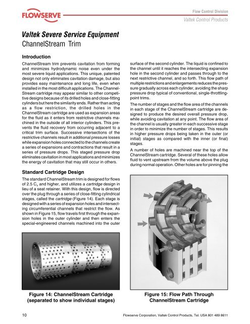
<strong>Valtek</strong> <strong>Severe</strong> <strong>Service</strong> <strong>Equipment</strong>ChannelStream TrimIntroductionChannelStream trim prevents cavitation from formingand minimizes hydrodynamic noise even under themost severe liquid applications. This unique, patenteddesign not only eliminates cavitation damage, but alsoprovides easy maintenance and long life, even wheninstalled in the most difficult applications. The Channel-Stream cartridge may appear similar to other competitivedesigns because of its drilled holes and close-fittingcylinders but here the similarity ends. Rather than actingas a flow restriction, the drilled holes in theChannelStream cartridge are used as expansion areasfor the fluid as it enters from restrictive channels machinedin the outside of all interior cylinders. This preventsthe fluid recovery from occurring adjacent to acritical trim surface. Successive intersections of therestrictive channels result in additional pressure losseswhile expansion holes connected to the channels createa series of expansions and contractions that result in aseries of pressure drops. This staged pressure dropeliminates cavitation in most applications and minimizesthe energy of cavitation that may still occur in others.Standard Cartridge DesignThe standard ChannelStream trim is designed for flowsof 2.5 C Vand higher, and utilizes a cartridge design inlieu of a seat retainer. With this design, flow is directedover the plug through a series of close-fitting cylindricalstages, called the cartridge (Figure 14). Each stage isdesigned with a series of expansion holes and intersectingcircumferential channels that restrict the flow. Asshown in Figure 15, flow travels first through the expansionholes in the outer cylinder and then enters thespecial-engineered channels machined into the outersurface of the second cylinder. The liquid is confined tothe channel until it reaches the intersecting expansionhole in the second cylinder and passes through to thenext restrictive channel, and so forth. This flow path ofmultiple restrictions and enlargements reduces the pressuregradually across each cylinder, avoiding the sharppressure drop typical of conventional, single-throttlingpointtrims.The number of stages and the flow area of the channelsin each stage of the ChannelStream cartridge are designedto produce the desired overall pressure drop,while avoiding cavitation at any point. The flow area ofthe channel is usually greater in each successive stagein order to minimize the number of stages. This resultsin higher pressure drops being taken in the outer (orinitial) stages as compared with the inner (or final)stages.A number of holes are machined near the top of theChannelStream cartridge. Several of these holes allowfluid to vent upstream from the volume above the plugduring normal operation. Other holes are for pinning theFigure 14: ChannelStream Cartridge(separated to show individual stages)Figure 15: Flow Path ThroughChannelStream Cartridge10Flowserve Corporation, <strong>Valtek</strong> Control Products, Tel. USA 801 489 8611