Valtek Severe Service Equipment
Valtek Severe Service Equipment
Valtek Severe Service Equipment
- No tags were found...

Create successful ePaper yourself
Turn your PDF publications into a flip-book with our unique Google optimized e-Paper software.
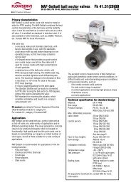
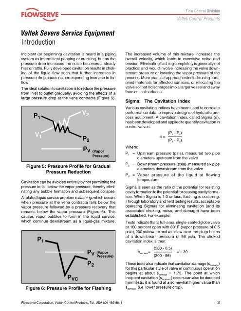
<strong>Valtek</strong> <strong>Severe</strong> <strong>Service</strong> <strong>Equipment</strong>IntroductionIncipient (or beginning) cavitation is heard in a pipingsystem as intermittent popping or cracking, but as thepressure drop increases the noise becomes a steadyhiss or rattle. Fully developed cavitation results in chokingof the liquid flow such that further increases inpressure drop cause no corresponding increase in theflow.The ideal solution to cavitation is to reduce the pressurefrom inlet to outlet gradually, avoiding the effects of alarge pressure drop at the vena contracta (Figure 5).P1P 2V 1V 2P V (VaporPressure)Figure 5: Pressure Profile for GradualPressure ReductionCavitation can be avoided entirely by not permitting thepressure to fall below the vapor pressure, thereby eliminatingany bubble formation and subsequent collapse.A related liquid service problem is flashing, which occurswhen pressure at the vena contracta falls below thevapor pressure followed by a pressure recovery thatremains below the vapor pressure (Figure 6). Thiscauses vapor bubbles to form in the liquid service,which continue downstream as a liquid-gas mixture.The increased volume of this mixture increases theoverall velocity, which leads to excessive noise anderosion. Eliminating flashing completely is generally notpractical and would involve increasing the valve downstreampressure or lowering the vapor pressure of theprocess. More practical approaches include using hardenedmaterials for affected surfaces, or relocating thevalve so that it discharges into a larger vessel and awayfrom critical surfaces.Sigma: The Cavitation IndexVarious cavitation indices have been used to correlateperformance data to improve designs of hydraulic processequipment. A cavitation index, called Sigma (σ),has been developed and applied to quantify cavitation incontrol valves:σ = (P - P ) 1 v(P 1- P 2)Where:P 1= Upstream pressure (psia), measured two pipediameters upstream from the valveP 2= Downstream pressure (psia), measured six pipediameters downstream from the valveP V= Vapor pressure of the liquid at flowingtemperatureSigma is seen as the ratio of the potential for resistingcavity formation to the potential for causing cavity formation.When Sigma is 1.0 or less, flashing is occurring.Through laboratory and field testing results, acceptableoperating Sigmas for eliminating cavitation (and itsassociated choking, noise, and damage) have beenestablished. For example:Tests indicate that a full-area, single-seated globe valveat 100 percent open with 80° F (vapor pressure of 0.5psia), 200 psia water and with flow-over-the-plug chokesat a downstream pressure of 56 psia. The chokedcavitation index is then:P 1P 2P VCP V(VaporPressure)Figure 6: Pressure Profile for Flashings choked= (200 - 0.5) = 1.39(200 - 56)These tests also indicate that cavitation damage (s damage)for this particular style of valve in continuous operationbegins at about s damage= 1.73. The point at whichincipient cavitation (s incipient) occurs can also be deducedfrom tests; it is found at a somewhat higher value thans damage(i.e. lower pressure drop).Flowserve Corporation, <strong>Valtek</strong> Control Products, Tel. USA 801 489 86113