Pagine interne MPS/MST - MP Filtri
Pagine interne MPS/MST - MP Filtri
Pagine interne MPS/MST - MP Filtri
- No tags were found...

Create successful ePaper yourself
Turn your PDF publications into a flip-book with our unique Google optimized e-Paper software.
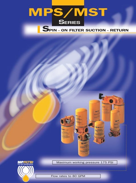
<strong><strong>MP</strong>S</strong>/<strong>MST</strong>SERIESSPIN - ON FILTER SUCTION - RETURN®Maximum working pressure 175 PSIFlow rates to 80 GPM
<strong>MP</strong> <strong>Filtri</strong> - Filtration technologyFilter element:MaterialsA SeriesInorganic microfibrePre-filtration andExternal support mediaExternal wire meshMicrofibre filtration mediaEnd caps:Galvanized steelInternal wire meshInternal support mediaInner supporttubeSupport tube:Galvanized steelSupport frames:Galvanized steel withan epoxy coating<strong>MP</strong> Filter elements - Conform to the followingISO standardsISO 2941 - Verification of collapse/burst resistance.ISO 2942 - Verification of fabrication integrity and determinationof the first bubble point.ISO 2943 - Verification of material compatibility with fluids.ISO 3723 - Method for end load test.ISO 3724 - Verification of flow fatigue characteristics.ISO 3968 - Evaluation of pressure drop versus flow characteristics.ISO 16889 - Multi-pass method for evaluating filtration performance.Element materialAbsolute filtrationA SeriesInorganic microfibre with acrilic supportContamination retentionas per ISO 16889: Multi-pass test.New improved ß ≥ 75filter elements withgreater efficiency andincreased dirt holdingcapacityFilterelementsß ≥ 2(50%)Dimensions for ß (µm) valuesß ≥ 20(95%)ß ≥ 75(98,7%)ß ≥ 200(99,5%)Filtration ratiosß2 ß10 ß20A03 – 2 2,4 3 20 > 10.000 > 10.000A06 – 3 4,6 6 8 > 2.000 > 10.000A10 3 6 7,8 10 1,5 ≥ 200 > 10.000A25 13 19 22 25 – > 1,5 > 35N.B. Other materials giving different degrees of filtration are available on request.∆ P(psi)100100100100Filtering areaFilter elementsTypeCS-CSG-CTA03/A06A10/A25050300300070500500100620620150840840Values in in 2Element materialNominal filtrationP SeriesResin - impregnated paperM SeriesSquare wire mesh (filtration degree is definedin microns by the maximum diameter of asphere corresponding to the mesh size)Filtering areaFilter elementsTypeCS-CSG-CTP10/P25M25050380160070650200100670310150900375CSGWSeriesResin - impregnated paperM60M90160160200200Values in n 2310310375375Type CSGWP10/P250503101504753
<strong>MP</strong> <strong>Filtri</strong> - SpecificationMaterialsHeadAluminiumBypass valveNylonWorkingtemperaturePressure filterbodyCollapse pressurefilter elementsBypass valveCalibration pressureSealsA Series: Nitrile (Buna-N)V Series: VitonMaximum working pressure up toBypass valve, differential opening pressure:IndicatorBrassFrom -13 to +230°FFor temperatures outside this range, pleaseconsult our Sales Network Organization175 psi60 psiS series: 4,0 psi ± 10% (<strong><strong>MP</strong>S</strong> series only)R series: 25 psi ± 10%Types of indicators for <strong><strong>MP</strong>S</strong> series “0” (<strong><strong>MP</strong>S</strong> 050-070-100…) and <strong>MST</strong> seriesVisual indicatorElectrical indicatorDescription:<strong><strong>MP</strong>S</strong> series filters are fitted with indicatorsswitching:Suction filters at a pressure of: 3 psi ± 10%Line filters at a pressure of:18 psi ± 10% (<strong><strong>MP</strong>S</strong> series only)Return filter at a pressure of:18 psi ± 10% (<strong><strong>MP</strong>S</strong>-<strong>MST</strong> series only)Suction filter: (<strong><strong>MP</strong>S</strong> series only)VS vacuum switchReturn and line filterVR colour coded pressure gaugescale 0 - 30 in Hgscale 0 - 30 psiTypes of indicators for <strong><strong>MP</strong>S</strong> series “1” (<strong><strong>MP</strong>S</strong> 051-071-101-151-301-351)<strong><strong>MP</strong>S</strong> filter series 1 (051-071-101… and so on)are fitted with, differential style indicators.Visual indicatorElectrical indicatorSuction filter (<strong><strong>MP</strong>S</strong> series only)“E0” Vacuum switch with change over contactReturn filterER Pressure switch with N.O. contactsEC Pressure switch with N.C. contacts1V - Z1 Series for Filter with bypass set switching at 18 psi ± 10%to 25 psiV6 - Z6 Series for Filter without bypass switching at 30 psi ± 10%N1 Series for Filter with bypass set switching at 18 psi ± 10%to 25 psiN6 Series for Filter without bypass switching at 30 psi ± 10%Visual-electricalindicator 1E - K1* Series for Filter with bypass set switching at 18 psi ± 10%to 25 psiE6 - K6* Series for Filter without bypass switching at 30 psi ± 10%*For K visual-electrical indicator, specify the voltage (il. K61 = LED: 24 volt)4Operational information:Switching at 3 psi ± 10%Max voltage: 250V 50÷60 HzMax current: 5 A resistive, 2 A inductiveProtection degree IP65Switching at 18 psi ± 10%Max voltage: 48V 50÷60 HzMax current: 0,5A resistive0,2A inductive{* 1 - 24 Volt2 - 115 Volt3 - 230 Volt
<strong>MP</strong> <strong>Filtri</strong> - SpecificationPressure differential indicator optionK - E - N SeriesSupply voltage (50/60 Hz)(V)Vca 125Vca 250Vcc 30Vcc 125Vcc 250Resistive load(A)5550,50,25Inductive load(A)2230,030,03CONNECTOR DIN 43650ELECTRICAL CONNECTIONE - N SERIESN.C.N.O.ELECTRICAL CONNECTIONK SERIESN.C.N.O.Visual V seriesVisual Z seriesA/F 32 mm1.61.38A/F 30 mm1.101.062.71Ø .63G1/2”Ø .63G1/2”Electrical N series1.5Visual led - Electrical K seriesLed1.5Visual - Electrical E series1.52A/F 30 mm2.56A/F 30 mm2.563.01.061.061.10A/F 32 mmØ .63G1/2”Ø .63G1/2”Ø .63G1/2”5
<strong>MP</strong> <strong>Filtri</strong> - SpecificationFluidCompatibilityFilter head and bowlscompatible for use with:• mineral oils(types HH-HL-HM-HR-HV-HG as per ISO 6743/4)• water-based emulsions(types HFAE-HFAS as per ISO 6743/4)• synthetic fluids(types HS-HFDR-HFDS-HFDU as per ISO 6743/4)• water-glycol (types HFC as per ISO 6743/4)SealsA SeriesNitrile (Buna-N) compatible with mineral oils(types HH-HL-HM-HR-HV-HG as per ISO 6743/4)water-based emulsions(types HFAE-HFAS as per ISO 6743/4)water - glycol (types HFC as per ISO 6743/4)V SeriesViton compatible with synthetic fluids(types HS-HFDR-HFDS-HFDU as per ISO 6743/4)Filter elementsAs per ISO 2943; suitable for mineral oils(types HH-HL-HM-HR-HV-HG as per ISO 6743/4)and synthetic fluids (A and M series only)(types HS-HFDR-HFDS-HFDU as per ISO 6743/4)For water-based emulsions (types HFAE-HFASas per ISO 6743/4) and fluids other thanthose mentioned, please consult our SalesNetwork Organization.International standards for contamination fluid controlA general (no direct) comparison between ISO 4406 and NAS 1638 is given in table below.Contamination Correspondent Recommended Typical applicationscodes codes filtrationISO 4406 NAS 1638 degree4µm(c) 6µm(c) 14µm(c) B x ≥ 7514 12 9 3 3 High precision andlaboratory servo-systems17 15 12 6 3-6 Robotic and servo-systems18 16 13 7 10-12 Very sensitive - highreliability systems20 18 15 9 12-15 Sensitive - reliable systems21 19 16 10 15-25 General equipment oflimited reliability23 21 18 12 25-40 Low - pressure equipmentnot in continuous service6
Selection& installation informationFilter elementstypesA SeriesAbsolute inorganic microfibrefiltration media, available in3, 6, 10 and 25 micronExample - A03, A06, A10 or A25P SeriesNominal cellulose impregnatedpaper media, available in 10and 25 micron.Example - P10 or P25M SeriesMetal mesh media, available in25, 60, and 90 micron.Example - M25, M60 or M90.Please refer to individual pressure drop curves to obtain filter assembly pressure drop informationThe following filter sizing recommendations are based using a mineral oil fluid at 150 SUS with a maximum total filter assembly(housing and filter element) pressure drop of 30% of the filter condition indicator (6 psi) for line and return filter and 1.15 psi for suction filter.Indicator portfor return line filterC - No. 2 Threaded holes2.36H1<strong><strong>MP</strong>S</strong> 050-070 Series1.50H0.86.55BA3.750.2.9INØ 3.801.50ø 3.0AOUTIndicator portfor suction line filterLengthsType050-051070-071Indicator for suction filter <strong><strong>MP</strong>S</strong> 050-070 (only for option G2-G3-G4-G6)Indicator for return filter <strong><strong>MP</strong>S</strong> 050-070 (only for option G2-G3-G4-G6)ø 1.57VS1/8” NPTø 1.57 1.34VR1/8” NPTA/F .551.34A/F .553.62.35ø 1.181.181/8” NPT1.50<strong><strong>MP</strong>S</strong> 051-071 Series3.75EO2.32A/F .551/8” NPTER - EC2.201.70A/F .950.95 Indicator portRevolvingPG 11ø Cable 8/10 mmPg 71.221.12050-051<strong><strong>MP</strong>S</strong> 070-071H7.089.76H17.8710.55Threadconnections<strong><strong>MP</strong>S</strong> SERIES 050-051 SIZESFilterassemblyA03A06A10A25P10M60-M90** Flow rates with 150 SUS fluid viscosity** Weight including filter elementTypeG1G2G3G4G5G6Line Flowrate gpm*10.511.612.715.314.5–Suction Flowrate gpm*2.32.93.74.74.26.3A3/4” BSP3/4” NPTSAE 12 - 1 1/16” - 12 UNSAE 8 - 3/4” - 16 UNF1” BSP1” NPTPort sizeBSP/NPT/SAESEETABLEBELOW<strong><strong>MP</strong>S</strong> SERIES 070-071 SIZESFilterassemblyA03A06A10A25P10M60-M90∆p psi1.51.00.5Line Flowrate gpm*12.013.014.016.715.3–Suction Flowrate gpm*2.93.44.05.34.76.9Port sizeBSP/NPT/SAESEETABLEBELOWB1/8” BSP1/8” NPT1/8” NPT1/8” NPT1/8” BSP1/8” NPTWeightlbs**2,2Weightlbs**2,9CM61/4” UNC1/4” UNC1/4” UNCM61/4” UNCSuction filter - Housing pressure dropIndicator for line filter <strong><strong>MP</strong>S</strong> 051-0711.5 1.5Led1.5200 2.0 4.0 6.0 8.0Flow rate gpmReturn line filter - Housing pressure drop6.0Z1.41.6A/F 30 mmV1.65A/F 32 mmN2.56A/F 30 mmK2.56A/F 30 mm3.0A/F 32 mmE∆p psi4.02.000 6.5 13 19.5 267Flow rate gpm
Selection& installation informationPlease refer to individual pressure drop curves to obtain filter assembly pressure drop informationThe following filter sizing recommendations are based using a mineral oil fluid at 150 SUS with a maximum total filter assembly(housing and filter element) pressure drop of 30% of the filter condition indicator (6 psi) for line and return filter and 1.15 psi for suction filter.Indicator portfor return line filterH13.7H2.01.2A<strong><strong>MP</strong>S</strong> 100-150 SeriesB0.6IN5.21.4LengthsType100-101150-151Indicator for suction filter <strong><strong>MP</strong>S</strong> 100-150 (only for option G2-G3)VSEO1/8” NPTC - No. 2 Threaded holesØ 5.038OUT2.1A/F .55ø 5.2.27Indicator portfor suction line filter2.0<strong><strong>MP</strong>S</strong> 101-151 Series1.182.325.21.1Revolving<strong><strong>MP</strong>S</strong>Indicator port1.3H9.4811.26100-101150-151H111.5012.25Threadconnections<strong><strong>MP</strong>S</strong> SERIES 100-101 SIZESFilterassemblyA03A06A10A25P10M60-M90** Flow rates with 150 SUS fluid viscosity** Weight including filter elementTypeG1G2G3Line Flowrate gpm*19.822.529.037.034.0–Suction Flowrate gpm*4.25.06.610.59.217.0A1 1/4” BSP1 1/4” NPTSAE 20 - 1 5/8” - 12 UNPort sizeBSP/NPT/SAE<strong><strong>MP</strong>S</strong> SERIES 150-151 SIZESFilterassemblyA03A06A10A25P10M60-M90Line Flowrate gpm*22.526.430.442.337.0–Suction Flowrate gpm*4.75.87.911.910.518.0B1/8” BSP1/8” NPT1/8” NPTWeightlbs**1 1/4” 4.88Port sizeBSP/NPT/SAEWeightlbs**1 1/4” 5.10CM85/16” UNC5/16” UNCø 1.57 1.343.62A/F .55PG 11ø Cable 8/10 mm1.5Suction filter - Housing pressure dropIndicator for return filter <strong><strong>MP</strong>S</strong> 100-150 (only for option G2-G3)ø 1.57VR1/8” NPTA/F .551.34.35ø 1.181/8” NPTIndicator for line filter <strong><strong>MP</strong>S</strong> 101-1511/8” NPTER - EC2.201.70Pg 7A/F .951.221.00.500 6.5 13 19.5 26Flow rate gpmReturn line filter - Housing pressure drop6.0∆p psi1.41.61.651.5 1.5Led2.562.561.523.0∆p psi4.02.0A/F 30 mmA/F 32 mmZVNA/F 30 mmKA/F 30 mmA/F 32 mmE00 15 30 45 60Flow rate gpm8
Selection& installation informationPlease refer to individual pressure drop curves to obtain filter assembly pressure drop informationThe following filter sizing recommendations are based using a mineral oil fluid at 150 SUS with a maximum total filter assembly(housing and filter element) pressure drop of 30% of the filter condition indicator (6 psi) for line and return filter and 1.15 psi for suction filter.H1 H1H H0.31.8 2.75 2.95CAINThread connection forindicator (return)OUTB<strong><strong>MP</strong>S</strong>200250Thread connection forindicator (suction)<strong><strong>MP</strong>S</strong> SERIES 200 SIZESFilterassemblyA03A06A10A25P10M60-M90Line Flowrate gpm*34.345.058.076.771.4–Suction Flowrate gpm*7.911.917.029.026.431.7<strong><strong>MP</strong>S</strong> SERIES 250 SIZESFilterassemblyA03Line Flowrate gpm*47.6Suction Flowrate gpm*13.2Port sizeBSP/NPT/SAEWeightlbs**1 1/2” 8.90Port sizeBSP/NPT/SAEWeightlbs**A0655.515.8Ø 5.05.5A10A2566.082.021.033.01 1/2” 9.35P1074,031.2M60-M90–34.3LengthsType200250H8.5010.27H19.5011.26Threadconnections** Flow rates with 150 SUS fluid viscosity** Weight including filter elementTypeG1G2G3A1 1/2” BSP1 1/2” NPTSAE 24 - 1 7/8” - 12 UNB1/8” BSP1/8” NPT1/8” NPTCM103/8” UNC3/8” UNCIndicator for suction filter (only for option G2-G3)VS1/8” NPTA/F .55ø 1.57 1.343.621.18EO2.32RevolvingPG 11ø Cable 8/10 mmA/F .55∆p psiSuction filter - Housing pressure drop1.51.00.500 10 20 30 40.351/8” NPTFlow rate gpmIndicator for return filter (only for option G2-G3)6.0Return line filter - Housing pressure dropø 1.57VR1/8” NPTA/F .551.34ø 1.181/8” NPTER - EC2.201.70A/F .95Pg 71.22∆p psi4.02.000 25 50 75 1009Flow rate gpm
Selection& installation informationH1Please refer to individual pressure drop curves to obtain filter assembly pressure drop informationThe following filter sizing recommendations are based using a mineral oil fluid at 150 SUS with a maximum total filter assembly(housing and filter element) pressure drop of 30% of the filter condition indicator (6 psi) for line and return filter and 1,15 psi for suction filter.H1.9BThread connection forindicator (suction)5.122.362.125 CThread connection forindicator (return line)Ø 5.0D11.145.9AOUTINA7.32F - No. 4 Threaded holesEThread connection forindicator (suction)Thread connection forindicator (return line)Indicator port for<strong><strong>MP</strong>S</strong> 301-351Thread connection forindicator (return line)LengthsType300-301350-351<strong><strong>MP</strong>S</strong>H10.4512.20Indicator for suction filter <strong><strong>MP</strong>S</strong> 300-350 (only for option G2-G3-F2)VSEO 2.32A/F .55Revolving Flangeconnections1/8” NPTø 1.57 1.343.62.351.18A/F .551/8” NPTPG 11ø Cable 8/10 mm300-301350-351H111.4213.20ThreadconnectionsTypeF1F2<strong><strong>MP</strong>S</strong> SERIES 300-301 SIZESFilterassemblyA03A06A10A25P10M60-M90Line Flowrate gpm*34.445.058.276.771.4–Suction Flowrate gpm*7.911.917.029.026.431.7** Flow rates with 150 SUS fluid viscosity** Weight including filter elementPort sizeBSP/NPT/SAE<strong><strong>MP</strong>S</strong> SERIES 350-351 SIZESFilterassemblyA03A06A10A25P10M60-M90TypeG1G2G31.5ALine Flowrate gpm*47.655.566.082.074–Suction Flowrate gpm*13.215.821.033.031.234.3A1 1/2” BSP1 1/2” NPTSAE 24 - 1 7/8” - 12 UN1 1/2” SAE 3000 PSI/M 1/8” BSP M121 1/2” SAE 3000 PSI/UNC 1/8” NPT 1/2” UNCBCWeightlbs**1 1/2” 12.0Port sizeBSP/NPT/SAEWeightlbs**1 1/2” 12.5B1/8” BSP1/8” NPT1/8” NPTD2.752.75E1.4061.406CM103/8” UNC3/8” UNCSuction filter - Housing pressure dropFM121/2” UNCIndicator for return filter <strong><strong>MP</strong>S</strong> 300-350 (only for option G2-G3-F2)VRER - ECø 1.571/8” NPTA/F .551.34ø 1.181/8” NPTIndicator for line filter <strong><strong>MP</strong>S</strong> 301-3512.201.70A/F .951.5 1.5LedPg 71.221.52∆p psi1.00.500 10 20 30 40Flow rate gpmReturn line filter - Housing pressure drop6.0Z1.41.6A/F 30 mmV1.65A/F 32 mmN2.56A/F 30 mmK2.56A/F 30 mm3.0A/F 32 mmE∆p psi4.02.000 25 50 75 10010Flow rate gpm
D e s c r i p t i o nFILTER ELEMENT SERIES -▲A A A▲▲▲▲▲CS CSG CSGWNewabsolute filter elementsindependently testedin the following Institutes:ThreadconnectionsTypeCS 050-070CS 100-150A3/4” BSP1 1/4”BSPTypeCSG 050-070CSG 100-150A1” - 12 UN1 1/2” - 16 UNTypeCSGW 050CSGW 150A1” - 12 UN1 1/2” - 16 UNUNI EN ISO 9001N° 037/9811
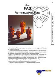
D e s c r i p t i o n<strong>MST</strong> - Suitable for installation on return lines, mounted tank top where the flow does not exceed 350 l/min.<strong>MST</strong> use spin - on canisters incorporating a bypass valve.To avoid oil leaks during maintenance, the canisters have a special anti-drain membrane.<strong>MST</strong> - filter is ideal for machine tool and agricultural applications.INTERNALBYPASS VALVENewabsolute filter elementsindependently testedin the following Institutes:ANTI-DRAINMEMBRANEINDICATOROPTIONSVISUALELECTRICALUNI EN ISO 9001N° 037/9812
Selection& installation informationFilter elementstypesA SeriesAbsolute inorganic microfibrefiltration media, available in3, 6, 10 and 25 micronExample - A03, A06, A10 or A25P SeriesNominal cellulose impregnatedpaper media, available in 10and 25 micron.Example - P10 or P25M SeriesMetal mesh media, available in25, 60, and 90 micron.Example - M25, M60 or M90.Please refer to individual pressure drop curves to obtain filter assembly pressure drop informationThe following filter sizing recommendations are based using a mineral oil fluid at 150 SUS with a maximum total filter assembly(housing and filter element) pressure drop of 30% of the filter condition indicator (6 psi) for line and return filter.3.54<strong>MST</strong> SERIES 050 SIZES2.75AØ .28<strong>MST</strong> 050-070FilterassemblyA03Line Flowrate gpm*11.0Port sizeBSP/NPT/SAEWeightlbs**A0613.22.2A1017.03/4” 2.662.75A25P1019.818.0IndicatorportIndicatorport<strong>MST</strong> SERIES 070 SIZESØ 3.78FilterassemblyA03A06A10A25P10Line Flowrate gpm*14.515.818.021.020.0Port sizeBSP/NPT/SAEWeightlbs**3/4” 3.35** Flow rates with 150 SUS fluid viscosity** Weight including filter elementH1HB - No. 2 Threaded holesThreadconnectionsTypeAG13/4” BSPG23/4” NPTG3 SAE 8 - 3/4” - 16 UNFLengthsB1/8” BSP1/8” NPT1/8” NPT.98TypeHH10507.488.20.35A07010.4311.15Ø 4.256.0Housing pressure dropIndicator (only for option G2-G3)VRA/F .55ø 1.571/8” NPT1.34ø 1.181/8” NPTER - EC2.201.70A/F .95Pg 71.22∆p psi4.02.000 6.5 13 19.5 26Flow rate gpm13
Selection& installation informationPlease refer to individual pressure drop curves to obtain filter assembly pressure drop informationThe following filter sizing recommendations are based using a mineral oil fluid at 150 SUS with a maximum total filter assembly(housing and filter element) pressure drop of 30% of the filter condition indicator (6 psi) for line and return filter.4.83.94AØ .35<strong>MST</strong> 100-150<strong>MST</strong> SERIES 100 SIZESFilterassemblyA03Line Flowrate gpm*21.0Port sizeBSP/NPT/SAEWeightlbs**2.83A06A1023.833.01 1/2” 5.23.94A2549.0P1046.3IndicatorportIndicatorport<strong>MST</strong> SERIES 150 SIZESØ 5.0FilterassemblyA03A06A10A25P10Line Flowrate gpm*23.829.037.055.550.3Port sizeBSP/NPT/SAEWeightlbs**1 1/2” 5.4** Flow rates with 150 SUS fluid viscosity** Weight including filter elementH1HB - No. 2 Threaded holesThreadconnectionsTypeAG11 1/2” BSPG21 1/2” NPTG3 SAE 20 - 1 5/8” - 12 UNFLengthsType H H1B1/8” BSP1/8” NPT1/8” NPT1.421001509.8411.0210.912.0.35AØ 5.246.0Housing pressure dropIndicator (only for option G2-G3)VRA/F .55ø 1.571/8” NPT1.34ø 1.181/8” NPTER - EC2.201.70A/F .95Pg 71.22∆p psi4.02.000 20 40 60 80Flow rate gpm14
Pressure drop informationGeneralPressure drop versus flow rate curve information for both housing and filter elements is in accordance with ISO 3968Filter assembly pressure drop - ∆p Total = ∆p Housing + ∆p Filter elementHousing pressure drop - The housing pressure drop is proportional to the fluid densityFilter element pressure drop - Filter element pressure drop is proportional to kinematic viscosity therefore always check thefluid operating temperature and fluid type to obtain the working viscosity according to the following formula:∆p 1 Filter element = (working viscosity/brochure viscosity) x ∆p filter elementBrochure viscosity 150 SUSFilter assembly sizing exampleSelection :• Customer requires a 26 gpm filter assembly• Mineral oil fluid: 230 SUS at 104 °F• 25 micron absolute filtration• return line application•Housing pressure drop - <strong><strong>MP</strong>S</strong> 100/101 with 26 gpm ∆p = 1.85 psi (see curve on page 8)•Filter element pressure drop brochure viscosity - CS100A25 with 26 gpm ∆p = 1.3 psi (see curve on page 17)•Filter element pressure drop working viscosity - With 230 SUS ∆p 1 = 1.3 x (230/150) = 2.0 psi•Filter assembly pressure drop ∆p Total = ∆p Housing + ∆p 1 Filter element = 1.85 + 2.0 = 3.85 psi* {Acceptable pressure drop value,as per our recommendationsBypass valves pressure dropThe curves were obtained using amineral oil with a density of 0,86The ∆p varies proportionally to the density.∆p psi604020R SERIESS SERIES<strong><strong>MP</strong>S</strong> 50- 70∆p psi604020<strong><strong>MP</strong>S</strong> 100 - 150R SERIESS SERIES0 0 6.5 13 19.5 26Flow rate gpm0 0 10 20 30 40Flow rate gpm60<strong>MST</strong> 50- 7060<strong>MST</strong> 100 - 150R series: Return filterS series: Suction filter∆p psi40200 0 25 50 75 100∆p psi40200 0 25 50 75 100Flow rate gpmFlow rate gpm15
SUCTION FILTERFilter elements - P/M SeriesThe curves were obtained using a mineral oil with a kinematic viscosity of 150 SUS.The ∆p varies proportionally to the fluid kinematic viscosity.1.5CS - CSG 50 P/<strong>MP</strong>101.5CS - CSG 70 P/M∆p psi1.00.500 2.0 4.0 6.0 8.0P25M60M90∆p psi1.0P100.5P25M600 M900 2.0 4.0 6.0 8.0Flow rate gpmFlow rate gpm1.5CS - CSG 100 P/<strong>MP</strong>101.5CS - CSG 150 P/M∆p psi1.00.500 10 20 30 40P25M60M90∆p psi1.0P100.5P25M600 M900 10 20 30 40Flow rate gpmFlow rate gpmFilter elements - A SeriesThe curves were obtained using a mineral oil with a kinematic viscosity of 150 SUS.The ∆p varies proportionally to the fluid kinematic viscosity.∆p psi1.51.00.5A03CS - CSG 50AA06A10A25∆p psi1.51.00.5CS - CSG 70 P/MA03A06A10A2500 2.0 4.0 6.0 8.0Flow rate gpm00 2.0 4.0 6.0 8.0Flow rate gpm∆p psi1.51.00.5A03CS - CSG 100AA06A10A25∆p psi1.51.00.5CS - CSG 150AA03A06A10A2500 4.0 8.0 12.0 16.0Flow rate gpm00 4.0 8.0 12.0 16.0Flow rate gpm16
RETURN FILTERFilter elements - P/M SeriesThe curves were obtained using a mineral oil with a kinematic viscosity of 150 SUS.The ∆p varies proportionally to the fluid kinematic viscosity.6.0CS - CT - CSG 50 P/M6.0CS - CT - CSG 70 P/M∆p psi4.02.000 6.5 13 19.5 26P10P25M60M90∆p psi4.0P102.0P25M6000 6.5 13 19.5M9026Flow rate gpmFlow rate gpm∆p psi6.04.02.0CS - CT - CSG 100 P/M00 20 40 60 80P10P25M60M90∆p psi6.04.0CS - CT - CSG 150 P/<strong>MP</strong>102.0P25M600 M900 20 40 60 80Flow rate gpmFlow rate gpmFilter elements - A SeriesThe curves were obtained using a mineral oil with a kinematic viscosity of 150 SUS.The ∆p varies proportionally to the fluid kinematic viscosity.∆p psi6.04.02.0CS - CT - CSG 50 AA03A06A10A25∆p psi6.04.02.0CS - CT - CSG 70 AA03A06A10A2500 6.5 13 19.5 26Flow rate gpm00 6.5 13 19.5 26Flow rate gpm∆p psi6.04.02.0A03A06CS - CT - CSG 100 AA10A25∆p psi6.04.02.0CS - CT - CSG 150 AA03A06A10A2500 20 40 60 80Flow rate gpm00 20 40 60 80Flow rate gpm17
Ordering information<strong><strong>MP</strong>S</strong>Port optionsType <strong><strong>MP</strong>S</strong> 050-071 <strong><strong>MP</strong>S</strong> 100-151 <strong><strong>MP</strong>S</strong> 200-250 <strong><strong>MP</strong>S</strong> 300-351G1G2G3G4G5G6F1F2Nominal sizesSeries 0 Series 1050 051070 071100 101150 151200 –250 –300 301350 351Bypass valveFilter series “0”C With bypass 25 psi - 4 indicator portsO Without bypass with indicator portson suctionP Without bypass with indicator portson returnR with bypass 25 psi and indicatorports on returnS With bypass 4.5 psi and indicatorports on suctionU Without bypass without indicator portsFilter series “1”R With bypass 25 psiP Without bypass3/4” BSP3/4” NPTSAE 12SAE 81” BSP1” NPT––G4 Option without bypass onlyCSCSGCSGWSeries1 1/4” BSP1 1/4” NPTSAE 20European std. filter elementUSA standard filter elementUSA standard filter element(water removal type)–––––1 1/2” BSP1 1/2” NPTSAE 24–––––1 1/2” BSP1 1/2” NPTSAE 24–––1 1/2” SAE3000 Psi/M1 1/2” SAE3000 Psi/UNCFilter condition indicatorS With threaded hole onlyT With plugIndicators for suctions filters (<strong><strong>MP</strong>S</strong> series only)VS Visual vacuum gaugeEO Electrical vacuum switch exchange contactIndicators for return filters (for <strong><strong>MP</strong>S</strong>/<strong>MST</strong> series)VR Colour coded pressure gaugeER Pressure switch with N.O. contactsEC Pressure switch with N.C. contactsDifferential Indicators for line filters(only for series “1”)S With threaded hole onlyT2 Plug for indicator port1V Visual 15 psiV6 Visual 30 psiZ1 Visual 18 psiZ6 Visual 30 psiN1 Electrical 18 psiN6 Electrical 30 psi1E Visual-electrical 18 psiE6 Visual-electrical 30 psi{* 1 - 24 VoltK1* Visual-Electrical 18 psi 2 - 115 VoltK6* Visual-Electrical 30 psi 3 - 230 Volt*For K visual-electrical indicator, specify the voltage (f.i. K61)A Nitrile (Buna - N)V VitonSealsFilter elements M/P seriesP10P25 Resin-impregnated paper ßx ≥ 2M25M60 Square wire meshM90Filter elements A seriesA03A06Inorganic microfibre ßx ≥ 75A10A25Nominal sizes050 use 1 element for <strong><strong>MP</strong>S</strong> 050-051070 use 1 element for <strong><strong>MP</strong>S</strong> 070-071100 use 1 element for <strong><strong>MP</strong>S</strong> 100-101100 use 2 elements for <strong><strong>MP</strong>S</strong> 200100 use 2 elements for <strong><strong>MP</strong>S</strong> 300-301150 use 1 element for <strong><strong>MP</strong>S</strong> 150-151150 use 2 elements for <strong><strong>MP</strong>S</strong> 250150 use 2 elements for <strong><strong>MP</strong>S</strong> 300-301CSReplacement element<strong>MP</strong> <strong>Filtri</strong> - Filtration products will only be guaranteed if original <strong>MP</strong> <strong>Filtri</strong>replacement elements and spares are usedData held in this publication is given only for indicative purposes. <strong>MP</strong> <strong>Filtri</strong> reserves to introducemodifications to described items for technical or commercial reasons. Copyright reserved.18
Ordering information<strong>MST</strong>050070100150Nominal sizesFilter elements indicatorS With threaded hole onlyT With plugVR Colour coded pressure gaugeER Pressure switch with N.O. contactsEC Pressure switch with N.C. contactsA Nitrile (Buna - N)V VitonSealsBBypass valveCalibration: 25 psiA Nitrile (Buna - N)V VitonSealsType <strong>MST</strong> 050-070 <strong>MST</strong> 100-150 P10P25G1 3/4” BSP 1 1/2” BSPM25M60Resin-impregnated paper ßx ≥ 2Square wire meshG2 3/4” NPT 1 1/2” NPTM90G3Port optionsSAE 8SAE 20Filter elements M/P seriesFilter elements A seriesA03A06Inorganic microfibre ßx ≥ 75A10A25CTReplacement element<strong>MP</strong> <strong>Filtri</strong> - Filtration products will only be guaranteed if original <strong>MP</strong> <strong>Filtri</strong>replacement elements and spares are usedData held in this publication is given only for indicative purposes. <strong>MP</strong> <strong>Filtri</strong> reserves to introducemodifications to described items for technical or commercial reasons. Copyright reserved.19