Carlo Gavazzi Energy Management EM 26-96 - Sensors Incorporated
Carlo Gavazzi Energy Management EM 26-96 - Sensors Incorporated
Carlo Gavazzi Energy Management EM 26-96 - Sensors Incorporated

You also want an ePaper? Increase the reach of your titles
YUMPU automatically turns print PDFs into web optimized ePapers that Google loves.
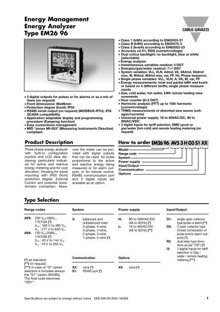
<strong>EM</strong><strong>26</strong> <strong>96</strong>Digital input specificationsNumber of inputs 3Input frequency 20Hz max, duty cycle 50%Prescaler adjustment From 0,1 to 999,9 m 3 orkWh/pulseContact measuring voltage 5VDC +/- 5%Contact measuring current 10mA maxInput impedance680ΩContact resistance≤100Ω, closed contact≥500kΩ, open contactWorking modesSelectable:• total and partial energymeters (kWh and kvarh)without digital inputs;• total and partial energymeters (kWh and kvarh)managed by time periods(t1-t2-t3-t4), W dmd synchronisation(the synchronisationis made every timethe tariff changes) andGAS (m 3 ) or WATER (hotcoldm 3 ) or remote heating(kWh) meters;NoteInsulation• total and partial energymeters (kWh and kvarh)managed by time periods(t1-t2), W dmd synchronisation(the synchronisationis made independently ofthe tariff selection) andGAS (m 3 ) or WATER (hotcoldm 3 ) or remote heating(kWh) meters;• total energy (kWh, kvarh)and GAS, WATER (hot-coldm 3 ) and remote heatingmeters (3 choices only).The energy metering isonly made by means of theanalogue inputs.By means of optocouplers,4000 VRMS digital inputsto measuring inputs.4000 VRMS digital inputsto power supply input.Software functionsPassword Numeric code of max. 4digits; 2 protection levelsof the programming data:1st levelPassword “0”, no protection;2nd level Password from 1 to 9999,all data are protectedSystem selectionSystem 3-Ph.n unbalanced load 3-phase (4-wire);3-phase (3-wire).System 3-Ph.1 balanced loadSystem 2-PhSystem 1-PhTransformer ratioVT (PT)3-phase (3-wire) one currentand 3-phase to phasevoltage measurements.3-phase (4-wire) one currentand one-phase (L1) toneutral voltage measurement.2-phase (3-wire).1-phase (2-wire).1.0 to 999.9 / 1000 to6000.CT 1.0 to 999.9 / 1000 to 9999/ 10.00k to 60.00k.The maximum power beingmeasured cannot exceed210 MW (calculated asmaximum input voltageand current, see the“Accuracy” paragraph (onpage 2). The maximum VTby CT ratio is 48600. If thecurrents and/or voltagesbeing measured exceedFilterOperating rangeFiltering coefficient 1 to 32Filter actionDisplayingAlarm highlightResettheir maximum limits, thedisplay shows the errormessage “EEEE”. For MIDcompliant applications themaximum power beingmeasured is 25 MW.0 to 100% of the input displayscaleMeasurements, serial output(fundamental variables:V, A, W and their derivedones).Up to 3 variables per pageSee « Display pages » 8different set of variablesavailable (see « Displaypages ») according to theapplication being selectedIn case of alarm and if therelevant function isenabled, the displaychanges the colour alternativelyfrom white backlightto blue backlight and viceversa.By means of the frontjoystick:- dmd and max. dmd;- total energies andgas/water: kWh, kvarh;- partial energies andtariffs: kWh, kvarh4 Specifications are subject to change without notice <strong>EM</strong>2 6<strong>96</strong> DS ENG 190308
<strong>EM</strong><strong>26</strong> <strong>96</strong>Software functions (cont.)Harmonic analysisEasy connection functionUp to the 15th harmonicson single current and voltageFor all the display selections,both energy andpower measurements areindependent of the currentdirection. The displayedenergy is always “imported”with the only exceptionof “F” and “H” types (see“display pages” table). Forthese latter selections theenergies can be either“imported” or “exported”depending on the currentdirection.General specificationsOperating temperatureStorage temperatureInstallation categoryInsulation (for 1 minute)Dielectric strengthNoise rejection CMRR<strong>EM</strong>CElectrostatic dischargesImmunity to irradiatedElectromagnetic fieldsBurst-25°C to +55°C (-13°F to131°F) (R.H. from 0 to 90%non-condensing @ 40°C)according to EN62053-21and EN62053-23-30°C to +70°C (-22°F to140°F) (R.H. < 90% noncondensing@ 40°C)according to EN62053-21and EN62053-23Cat. III (IEC60664,EN60664)4000 VRMS between measuringinputs and powersupply.4000 VRMS between powersupply and RS485 digitaloutputs4000 VRMS for 1 minute100 dB, 48 to 62 HzAccording to EN62052-1115kV air discharge;Test with current: 10V/mfrom 80 to 2000MHz;Test without any current:30V/m from 80 to2000MHz;On current and voltagemeasuring inputs circuit:4kVImmunity to conducteddisturbances10V/m from 150KHz to80MHzSurgeOn current and voltagemeasuring inputs circuit:4kV; on “L” auxiliary powersupply input: 1kV;Radio frequency suppression According to CISPR 22Standard complianceSafetyIEC60664, IEC61010-1EN60664, EN61010-1EN62052-11MetrologyEN62053-21, EN62053-23.MID ”annex MI-003”Pulse outputDIN43864, IEC62053-31ApprovalsCE, ULConnectionsScrew-typeCable cross-section area Max. 1.5 mm 2HousingDimensions (WxHxD) <strong>96</strong> x <strong>96</strong> x 63 mmMaterialABS,self-extinguishing: UL 94 V-0MountingPanel mountingProtection degreeFrontIP50Screw terminalsIP20WeightApprox. 400 g (packingincluded)Power supply specificationsAuxiliary power supplyL: 18 to 60VAC/DC;H: 90 to <strong>26</strong>0VAC/DC(48 to 62Hz)Power consumptionAC: 6VADC: 3.5 WSpecifications are subject to change without notice <strong>EM</strong>2 6<strong>96</strong> DS ENG 190308 5
<strong>EM</strong><strong>26</strong> <strong>96</strong>AccuracykWh, accuracy (RDG) depending on the current+1.5%+1%0%-1%-1,5%Errorkvarh, accuracy (RDG) depending on the current+2,5%+2%0%-2%-2,5%ErrorPF=10.25A0.5A5A (In)10A (Imax)sinϕ=10.1A0.25A5A (In)10A (Imax)PF=L0.5or C0.80.5A1A5A (In)Accuracy limits (Active energy)Start-up current: 10mA10A (Imax)sinϕ=0.50.25A0.5A5A (In)Accuracy limits (Reactive energy)Start-up current: 10mA10A (Imax)MID “Annex MI-003” complianceAccuracyAV5-AV6 models0.9 Un ≤ U ≤ 1.1 Un;0.98 fn ≤ f ≤ 1.02 fn;fn: 50 or 60Hz;cosϕ: 0.5 inductive to 0.8capacitive.Class BI st: 0.01A;I min: 0.05A;Operating temperature<strong>EM</strong>C complianceI tr: 0.25A;I n: 5A;I max: 10A-25°C to +55°C (-13°F to131°F) (R.H. from 0 to 90%non-condensing @ 40°C)E2Used calculation formulasPhase variablesInstantaneous effective voltageSystem variablesEquivalent three-phase voltage<strong>Energy</strong> meteringInstantaneous active powerInstantaneous power factorPFInstantaneous effective currentInstantaneous apparent powerInstantaneous reactive powerThree-phase reactive powerThree-phase active powerThree-phase apparent powerThree-phase power factor(TPF)Where:P= active power;Q= reactive power;t 1, t 2 =starting and ending time pointsof consumption recording;nj= time unit;∆t= time interval between two successivepower consumptions;n 1, n 2 = starting and ending discretetime points of consumption recordingWhere: n= sample number6 Specifications are subject to change without notice <strong>EM</strong>2 6<strong>96</strong> DS ENG 190308
<strong>EM</strong><strong>26</strong> <strong>96</strong>List of the variables that can be connected to:• RS485 communication port• Alarm outputs (“max” variable”, “energies” and “hour counter” excluded)• Pulse outputs (only “energies”)No Variable 1-phasesystem2-phasesystem3-ph. 4-wire 3-ph. 4-wire 3 ph. 3-wirebalanced sys. unbal. sys. bal. sys.3 ph. 3-wireunbal. sys.Notes1 V L-N sys o x x x x x sys=system2 V L1 x x x x x x3 V L2 o x x x x x4 V L3 o o x x x x5 V L-L sys o x x x x x sys=system6 V L1-2 o x x x x x7 V L2-3 o o x x x x8 V L3-1 o o x x x x9 A dmd max o x x x x x Highest “dmd”current amongthe phases (1)10 A L1 x x x x x x11 A L2 o x x x x x12 A L3 o o x x x x13 VA sys x x x x x x sys=system14 VA sys dmd x x x x x x sys=system (1)15 VA L1 x x x x x x16 VA L2 o x x x x x17 VA L3 o o x x x x18 var sys x x x x x x sys=system19 var L1 x x x x x x20 var L2 o x x x x x21 var L3 o o x x x x22 W sys x x x x x x sys=system23 W sys dmd x x x x x x sys=system (1)24 W L1 x x x x x x25 W L2 o x x x x x<strong>26</strong> W L3 o o x x x x27 PF sys x x x x x x28 PF L1 x x x x x x29 PF L2 o x x x x x30 PF L3 o o x x x x31 Hz x x x x x x32 Phase seq. o o x x x x33 Hours x x x x x x34 kWh (+) x x x x x x Total or by user35 kvarh (+) x x x x x x Total or by user36 kWh (+) x x x x x x Partial or by tariff37 kvarh (+) x x x x x x Partial or by tariff38 kWh (-) x x x x x x Total39 kvarh (-) x x x x x x Total40 m 3 Gas x x x x x x Total41 m 3 Cold H2O x x x x x x Total42 m 3 Hot H2O x x x x x x Total43 kWh H2O x x x x x x Total44 A L1 THD x x x x x x45 A L2 THD o x x x x x46 A L3 THD o o x x x x47 V L1 THD x x x x x x48 V L2 THD o x x x x x49 V L3 THD o o x x x x50 V L1-2 THD x x x x x x51 V L2-3 THD o x x x x x52 V L3-1 THD o o x x x x(x) = available(o) = not available (zero indication on the display)(1) Max. value with data storageSpecifications are subject to change without notice <strong>EM</strong>2 6<strong>96</strong> DS ENG 190308 7
<strong>EM</strong><strong>26</strong> <strong>96</strong>Display pagesNo1st variable 2nd variable 3rd variableApplicationsNote(1st line) (2nd line) (3rd line)A B C D E F G H1 Total kWh (+) W sys dmd W sys dmd max x x x x x x x2 kWh (+) A dmd max “PArt” “PArt” = Partial kWh (+) x x x3 Total kvarh (+) VA sys dmd VA sys dmd max x x x x x4 kvarh (+) VA sys “PArt” “PArt” = Partial kvarh (+) x x x5 Totalizer 1 (2) W sys (text) (3) (1) x x x x6 Totalizer 2 (2) W sys (text) (3) (1) x x x x7 Totalizer 3 (2) W sys (text) (3) (1) x x x x8 kWh (+) t1 (text) (4) W sys dmd (1) digital input enabled x x x x9 kWh (+) t2 (text) (4) W sys dmd (1) digital input enabled x x x x10 kWh (+) t3 (text) (4) W sys dmd (1) digital input enabled x x x x11 kWh (+) t4 (text) (4) W sys dmd (1) digital input enebled x x x x12 kvarh (+) t1 (text) (4) W sys dmd (1) digital input enabled x x x x13 kvarh (+) t2 (text) (4) W sys dmd (1) digital input enabled x x x x14 kvarh (+) t3 (text) (4) W sys dmd (1) digital input enabled x x x x15 kvarh (+) t4 (text) (4) W sys dmd (1) digital input enabled x x x x16 kWh (+) X W X User X (1) specific function enabled x17 kWh (+) Y W Y User Y (1) specific function enabled x18 kWh (+) Z W Z User Z (1) specific function enabled x19 Total kvarh (-) VA sys dmd VA sys dmd max x x20 Total kWh (-) W sys dmd W sys dmd max x x x21 Hours W sys PF sys x x x x22 Hours var sys PF sys x x x x23 W L1 W L2 W L3 x x x24 VA L1 VA L2 VA L3 x x25 var L1 var L2 var L3 x x<strong>26</strong> PF L1 PF L2 PF L3 x x27 V L1 V L2 V L3 x x x x x28 V L1-2 V L2-3 V L3-1 x x29 A L1 A L2 A L3 x x x30 Phase seq. V LN sys Hz x x x x x x x31 Phase seq. V LL sys Hz x x x32 ASY V LL sys % x x x33 ASY V LN sys % x x x34 THD A1 THD A2 THD A3 x x35 THD V1 THD V2 THD V3 x x36 THD V12 THD V23 THD V 31 x x37 Lot number Year DMD time x x x x x x x x38 CT ratio Value of CT System x x x x x x x x39 VT/PT ratio Value of VT Connection x x x x x x x x40 a Alarm 1 status Set-point value Variable type x x x x41 a Alarm 2 status Set-point value Variable type x x x x42 a Alarm 3 status Set-point value Variable type x x x x40 b Pulse 1 status Output pulse x x x x x x x x41 b Pulse 2 status Output pulse x x x x x x x x42 b Pulse 3 status Output pulse x x x x x x x x43 Serial port Address RS485 status x x x x x x x x0 Selector position which can be linked to any of the variable combinations listed above (No. from 1 to 36)1 Selector position which can be linked to any of the variable combinations listed above (No. from 1 to 36)2 Selector position which can be linked to any of the variable combinations listed above (No. from 1 to 36)Sel.pos.3Selector position which can be linked to any of the variable combinations listed above (No. from 1 to 36).In this position the front LED blinks proportionally to the reactive energy (kvarh) being measured(1) The page is available according to the enabled measurement. (2) m 3 Gas, m 3 Water, kWh remote heating. (3) Hot or Cold(water). (4) The active tariff is displayed with an “A” before the “t1-t2-t3-t4” simbols.8 Specifications are subject to change without notice <strong>EM</strong>2 6<strong>96</strong> DS ENG 190308
<strong>EM</strong><strong>26</strong> <strong>96</strong>Additional available information on the displayType 1st line 2nd line 3rt lineMeter information pag. 1 Lot (production day) Year of production dmd timeMeter information pag. 2 CT ratio Value of CT ratio System (1-2-3-phase)Meter information pag. 3 PT ratio Value of PT ratio Connection (2-3-4-wire)In case of alarm output Alarm output 1, 2 or 3 statusSet-point valueVariable typepag.4a(ON/OFF)In case of pulse output Pulse output 1,2 or 3 variable Output pulse weightpag. 4blink (kWh/kvarh)(kWh/kvarh per pulse)In case of communicationSerial port Address RS485 status (RX-TX)port pag.5List of selectable applicationsDescriptionNotesA Basic domestic Main energy meteringB Shopping centres Main energy meteringCAdvanced domesticMain energy metering (total and based on tariff), gas andwater meteringD Multi domestic (also camping and marinas) Main energy metering (3 by single phase)E Solar <strong>Energy</strong> meter with some basic power analyzer functionsF Industrial Main energy meteringG Advanced industrial <strong>Energy</strong> metering and power analysisH Advanced industrial for power generation Complete energy metering and power analysisInsulation between inputs and outputsMeasuring InputsRelayoutputOpen collectoroutputsComm. port Digital inputs Auxiliary power supplyMeasuring Inputs - 4kV 4kV 4kV 4kV 4kVRelay output 4kV - - 4kV - 4kVOpen collectoroutputs4kV - - 4kV - 4kVComm. port 4kV 4kV 4kV - 4kV 4kVDigital inputs 4kV - - 4kV - 4kVAux. power supply 4kV 4kV 4kV 4kV 4kV -NOTE: all the models with auxiliary power supply have, mandatory, to be connected to external current transformersbecause the insulation among the current inputs is just functional (100VAC).Tamper proof and display page selectionLock of programming with seal.Selection of up to 4 main pages(programmable by the user).Easy access to specific display pages.Specifications are subject to change without notice <strong>EM</strong>2 6<strong>96</strong> DS ENG 190308 9
<strong>EM</strong><strong>26</strong> <strong>96</strong>Wiring diagramsSystem type selection: 3P.n3-ph, 4-wire, unbalanced load Fig. 13-ph, 4-wire, unbalanced load Fig. 23-CT connection3-CT and 3-VT/PT connectionsSystem type selection: 3P.n3-ph, 3-wire, unbalanced load Fig. 33-ph, 3-wire, unbalanced load Fig. 43-ph, 3-wire, unbalanced load Fig. 53-CT connection3-CT and 2-VT/PT connections2-CT connections (ARON)3-ph, 3-wire, unbalanced load Fig. 6System type selection: 3P.13-ph, 3-wire, balanced load Fig. 71-CT connection3-ph, 3-wire, balanced load Fig. 82-CT and 2-VT/PT connections ARONNOTE: a 2-wire connection for voltage measurementis available across 15 and 17 .1-CT and 2-VT/PT connections10 Specifications are subject to change without notice <strong>EM</strong>2 6<strong>96</strong> DS ENG 190308
<strong>EM</strong><strong>26</strong> <strong>96</strong>Wiring diagramsSystem type selection: 2P2-ph, 3-wire Fig. 92-ph, 3-wire Fig. 10System type selection: 1P1-ph, 2-wire Fig. 112-CT connection2-CT and 2-VT/PT connections1-CT connectionSystem type selection: 1PAuxiliary power supply wiring diagrams1-ph, 2-wire Fig. 12100 to 230VAC/DC (“H” option) Fig.13 24 to 48VAC/DC (“L” option) Fig.141-CT and 1-VT connectionsF= 250V [T] 100mA F= 250V [T] 200mADigital inputs and RS485 port wiring diagramsDigital InputsRS485 portRS485 NOTE: additional devices provided with RS485 are connected in parallel. The termination of the serial output is carriedout only on the last instrument of the network, by means of a jumper between (A-) and (T).Specifications are subject to change without notice <strong>EM</strong>2 6<strong>96</strong> DS ENG 190308 11
<strong>EM</strong><strong>26</strong> <strong>96</strong>Open collector and relay outputs wiring diagramsOpen Collector Open Collector RelayRCRCRCRCRCRCOut 1VDCGNDOut 2VDCGNDOut 3VDCGNDVDCOut 1GNDVDCOut 2GNDVDCOut 3GND1 2 31 2 3GND referenceVDC referenceThe load resistances (RC) must be designed so that the close contact current is lower than100mA; the VDC voltage must be lower than or equal to 30VDC.Front panel description21341. DisplayLCD-type with alphanumeric indications to:- display configuration parameters;- display all the measured variables.2. SelectorTo select the desired display pages and to lock theprogramming.3. JoystickTo program the configuration parameters and scroll thevariables on the display.4. LEDRed LED blinking proportionally to the energy beingmeasured.Dimensions and Panel Cut-out91mm12 Specifications are subject to change without notice <strong>EM</strong>2 6<strong>96</strong> DS ENG 190308