Channel Generator - Carlo Gavazzi
Channel Generator - Carlo Gavazzi
Channel Generator - Carlo Gavazzi

You also want an ePaper? Increase the reach of your titles
YUMPU automatically turns print PDFs into web optimized ePapers that Google loves.
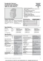
Dupline ® Carpark SystemType GP 3496 0005®Du lineFieldbusInstallationbus• Interface for Modbus-RTU with the function of a slave• Built-in Dupline ® <strong>Channel</strong> <strong>Generator</strong>• 128 I/O’s and DC power supply on 3 wires• RS232/RS422/RS485 port for making an interface tothe control system• Multidropping of up to 16 devices on RS485• LED-indications for supply, Dupline ® carrier and ComportTX• Galvanically isolated Com-port supplied by internalDC/DC converter• Sends out sync. signal for the Carpark sensorsProduct DescriptionGP 3496 0005 has beendesigned as a cost-effectivePlug & Play solution formaking an interface betweenDupline ® I/O’s and controlsystems. It has four functions:Dupline ® channel generator,power supplyType Selectionsynchronization (enables a3-wire system with supply),RS232/RS422/RS485 interface,and it produces a synchronizationsignal on twospecific Dupline ® addressesfor the Dupline ® Carparksystem.Ordering KeyType: Dupline ®H4-HousingCombined moduleInterface typeDC supplySupply PLC Interface Conformance Ordering no.GP3496000570020-30 VDC Modbus-RTU, GP 3496 0005 700Function code 01, 02, 03, 04, 05, 06 & 16Input/Output SpecificationsPower outputOutput voltage20-30 VDC (pulsating)Output current < 3.0 A @ 50ºCShort circuit protection 4 A quick acting fuseOutput voltage drop < 1.0 VDupline ® carrierOutput voltage8.2 V (pulsating)Current< 60 mAShort circuit protection YesScan time128 channels 132.2 ms64 channels 69.8 msCommunication portStandard RS 232/RS 422/ RS 485Split I/O / Normal mode Normal modeConnection9 pole female SUB-DDielectric voltageCom-port - Dupline ® 1 kVAC (rms)ProtocolModbus-RTUBaud rate 9600Data bits 8Start bit -Stop bit 1ParityNoneFlow-controlNoneInput/Output Specifications (Cont.)Pin assignment2-wire RS 485S/R Data line + (B) Pin 3S/R Data line - (A) Pin 8GND Pin 54-wire RS 485/RS 422R Data line + (B) Pin 3R Data line - (A) Pin 8S Data line + (B) Pin 2S Data line - (A) Pin 7Direction Pin 4(Connect to GND pin 5when using 4-wire communication)RS 232TX Pin 1RX Pin 9GND Pin 5Supply SpecificationsPower supply Overvoltage cat. III (IEC 60664)Operational voltage (V in) 20-30 VDCReverse polarity protection NoneCurrent consumption < 150 mA + Power loadPower dissipation< 5 WTransient protection voltage 800 VDielectric voltageSupply - Dupline ®NoneSupply - com-port 1 kVAC (rms)Specifications are subject to change without notice (29.08.2008) 1Dupline ® is a registered trademark. A product of the CARLO GAVAZZI Group
GP 3496 0005General SpecificationsPower ON delay2 sIndication forCom-port TxLED, redSupply ONLED, greenDupline ® carrierLED, yellowEnvironmentPollution degree 3 (IEC 60664)Operating temperature 0° to +50°C (+32° to +122°F)Storage temperature -50° to +85°C (-58° to +185°F)Mode of Operation®Du lineFieldbus InstallationbusHumidity (non-condensing) 20 to 80%Mechanical resistanceShock15 G (11 ms)Vibration2 G (6 to 55 Hz)DimensionsH4-HousingMaterial(see Technical information)Weight100 gDip-Switch SettingThe Dupline ® Master Moduleis a Dupline ® <strong>Channel</strong> <strong>Generator</strong>with the function of aslave. This means that the128 Dupline ® I/O’s can beread/ controlled by a PC/PLCor a Control board masterfrom many different suppliers.Up to 16 Dupline ® DMMcan be connected to thesame network and operatetogether with other modulesusing the same protocol asoperator panels, MMI’s frequencyinverters, I/O-modulesetc.The GP34960005 has beendeveloped for carpark installations.DIP sw 6 must be set inON-position, because theGP34960005 will then automaticallysend out a synchronizationsignal needed by thecarpark sensors. This synchronizationsignal ensures thattwo neighbour sensors are notmaking ultrasonic measurementssimultaneously. Pleasenote that the addresses P5, P6are reserved for this purpose,but also P7 and P8 cannot beused.The first sensor on a linemust be programmed to P5,the next to P6, the next toP5 and the next to P6. All thesensors must be programmedwith P5 or P6 onI/O6 respectively to avoidsimultaneous pulses. (seediagram below).Sw.1-4 On/Off: Device no. 1-16 (all off = 16)Sw.5 On: 64 Dupline ® channelsOff: 128 Dupline ® channelsSw.6 On: Synchronization function on P5 and P6activated.Off: Test mode for internal useDevice no. Sw1 Sw2 Sw3 Sw401 0 0 0 102 0 0 1 003 0 0 1 104 0 0 1 0-15 1 1 1 116 0 0 0 0Wiring DiagramsMultidropPeer to PeerDMM slave No. 1 DMM slave No. 2 DMM slave No. 3DMM slaveRS 485Duplinenet 1Multidrop CableConverterDuplinenet 2Multidrop CableDuplinenet 3Dupline netRS 232/RS 422/RS 485RS 232Programmer (Master)PC/PLCPC/PLC MasterCarpark with Synchronization Function1 2 3 456 7 83WI/O 6=P5 I/O 6=P6 I/O 6=P5+ -RS 232RS 485GP34960005Dipswich 6 = ONGP65202201GP65202201GP6520220121 22 23 24 25 26 27 28Supplypower outD- / GNDSupply in20-30 V DCPower outGNDDupline SignalD+2 Specifications are subject to change without notice (29.08.2008)Dupline ® is a registered trademark. A product of the CARLO GAVAZZI Group
GP 3496 0005Telegram StructureModbus-RTU Function code 01: Read Output Table (Data toreceivers) or 02: Read Input Table (Data from transmitters)Field NameExample (HEX) DescriptionSlave Address 07 Addressed to DMM no. 7Function 01/02 Read Output/Input TableStarting Point no. Hi 00 Read Dupline ® A6Starting Point no. Lo 05* (Point no. 6)Number of points 00 Always 00 01Number of points 01Error Check XX XX -®Du lineFieldbus InstallationbusResponse MessageField NameExample (HEX) DescriptionSlave Address 07 Addressed from DMM no. 7Function 01/02 Read Output/Input TableByte Count 01 1 byteData 01 Dupline ® <strong>Channel</strong> A6 (ON)Error Check XX XX -Modbus-RTU Function Code 03: Read Holding RegistersQuery messageField NameExample (HEX) DescriptionSlave Address 07 Addressed to DMM no. 7Function 03 Read RegistersStarting Address Hi 00 Starting register no. 0Starting Address Lo 00*Number of registers Hi 00 Read 5 Registers (Group A-J)Number of registers Lo 05Error Check XX XX -Response MessageField NameExample (HEX) DescriptionSlave Address 07 Addressed from DMM no. 7Function 03 Read RegistersByte Count 0A 10 bytes (5 Registers)Data Hi Register no. 1 00 Dupline ® Group BData Lo Register no. 1 40 Dupline ® Group A (A7 ON)- - - - - - -Data Hi Register no. 5 00 Dupline ® Group JData Lo Register no. 5 00 Dupline ® Group IError Check XX XX -Modbus-RTU Function Code 16: Write Multiple RegistersQuery MessageField NameExample (HEX) DescriptionSlave Address 07 Addressed to DMM no. 7Function 10 Write RegistersStarting Address Hi 00 Starting Register no. 0Starting Address Lo 00*Number of registers Hi 00 Write 5 Registers (Group A-J)Number of registers Lo 05Byte Count 0A 10 bytes (5 Registers)Data Hi Register 1 02 Dupline ® Group B (B2 ON)Data Lo Register 1 00 Dupline ® Group A- - - - - - -Data Hi Register 5 00 Dupline ® Group JData Lo Register 5 00 Dupline ® Group IError Check XX XX -Response MessageField NameExample (HEX) DescriptionSlave Address 07 Addressed from DMM no. 7Function 10 Write RegistersStarting Address Hi 00 Starting register no. 0Starting Address Lo 00*Number of registers Hi 00 Write 5 Registers (Group A-J)Number of registers Lo 05Error Check XX XX -* According to modbus protocol definition the starting address/point is transfered as one less than the number ofthe first reg/point to be read/written toMemory MappingRead Output Table (01). Read Input Table (02) and ForceSingle Output (05)Point no.Dupline ® <strong>Channel</strong>1 A12 A23 A3- -124 P4Specifications are subject to change without notice (29.08.2008) 3Dupline ® is a registered trademark. A product of the CARLO GAVAZZI Group
GP 3496 0005®Du lineFieldbus InstallationbusDigital read (Modbus Function 03) and Digital Write (Modbus Function 16)Reg. no. MSB HIGH BYTE LSB MSB LOW BYTE LSB1 B8 B7 B6 B5 B4 B3 B2 B1 A8 A7 A6 A5 A4 A3 A2 A12 D8 D7 D6 D5 D4 D3 D2 D1 C8 C7 C6 C5 C4 C3 C2 C13 F8 F7 F6 F5 F4 F3 F2 F1 E8 E7 E6 E5 E4 E3 E2 E14 H8 H7 H6 H5 H4 H3 H2 H1 G8 G7 G6 G5 G4 G3 G2 G15 J8 J7 J6 J5 J4 J3 J2 J1 I8 I7 I6 I5 I4 I3 I2 I16 L8 L7 L6 L5 L4 L3 L2 L1 K8 K7 K6 K5 K4 K3 K2 K17 N8 N7 N6 N5 N4 N3 N2 N1 M8 M7 M6 M5 M4 M3 M2 M18 P8 P7 P6 P5 P4 P3 P2 P1 O8 O7 O6 O5 O4 O3 O2 O1129 A1 A2 A3 A4 A5 A6 A7 A8130 B1 B2 B3 B4 B5 B6 B7 B8131 C1 C2 C3 C4 C5 C6 C7 C8132 D1 D2 D3 D4 D5 D6 D7 D8- - - - - - - - -144 P1 P2 P3 P4 P5 P6 P7 P8Dimensions (mm)H4-housingInstallation HintsNo TX-LEDChecksum ErrorWrong telegram structureHardware faultNo Dupline ® Carrier-LedShort circuitThe Checksum has beencalculated in a wrong way.See “Telegram Structure”Check the wiring. Try tosend the telegram-examplementioned in “TelegramStructure.Short circuit between thetwo Dupline ® wires.Delivery Contents1 x Master Module GP3496 0005 700Additional InformationModbus RTU memory map and Modbus RTU telegram structurecan be downloaded from our homepage www.dupline.com.Choose “download” and then “product specific”.4 Specifications are subject to change without notice (29.08.2008)Dupline ® is a registered trademark. A product of the CARLO GAVAZZI Group