Download - Carlo Gavazzi
Download - Carlo Gavazzi
Download - Carlo Gavazzi
- No tags were found...

Create successful ePaper yourself
Turn your PDF publications into a flip-book with our unique Google optimized e-Paper software.
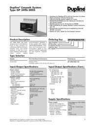
TechnicaldataDerating curvesand lossesDrive voltagelevelsDC busdesignMechanicalinstallation2 Derating curves and losses2.1 Derating curvesNOTENEMC filtersAC linereactor valuesMotor cablelengthsGeneraldataI/OSupply typesspecification OptionsThe de-rating curves are based on the results of heatruns that are carried out to measure temperatures at various key points (components) within thedrive at different switching frequencies / loads /ambient temperatures: These key points are things like:• Heatsink• Bridge rectifier• IGBTs• DC bus capacitors• Various electrolytic capacitors• Various resistors• etc.It is not always the heatsink temperature that is the limiting factor for the de-rating curves.At 3 and 6kHz, the limiting factor tends to be capacitor temperatures.At 12 and 18kHz, the limiting factor tends to be the heatsink temperature.At 3 and 6kHz, operating outside the de-rating curves will cause some of the capacitors within the drive to run outside of their maximum operatingtemperature and this could lead to the drives design operating lifetime being reduced.At 12 and 18kHz, operating outside the de-rating curves will cause the heatsink temperature to increase and may cause the drive to trip on Oht2. Ifthe auto-switching frequency change is enabled (Pr 5.35 = 0 [by default]), the drive will automatically decrease the switching frequency when theheatsink temperature rises above pre-determined levels to reduce the heatsink temperature. When the drive switches down the switching frequency,the drives display will flash 'hot'.It is important that operating within these de-rating curves is observed.Figure 2-1 Variflex Size A 0.25kW derating curve2.0Outputcurrent (A)1.51.03kHz6kHz12kHz18kHz0.5010 20 30405060Ambient Temperature ( o C)Variflex Technical Data 7Issue Number: 2www.carlogavazzi.com/acGross Automation (877) 268-3700 · www.carlogavazzisales.com · sales@grossautomation.com
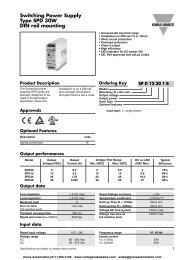
TechnicaldataDerating curvesand lossesDrive voltagelevelsDC busdesignMechanicalinstallationEMC filtersAC linereactor valuesMotor cablelengthsGeneraldataI/OSupply typesspecification OptionsFigure 2-2Outputcurrent (A)2.5Variflex Size A 0.37kW derating curve2.01.51.03kHz6kHz12kHz18kHz0.5010 20 30 40 50 60Ambient Temperature ( o C)Figure 2-3OutputCurrent (A)Variflex Size A 0.55kW derating curve3213kHz12kHz6kHz18kHz010 20 30 40 50 60Ambient Temperature (EC)8 Variflex Technical Datawww.carlogavazzi.com/ac Issue Number: 2Gross Automation (877) 268-3700 · www.carlogavazzisales.com · sales@grossautomation.com
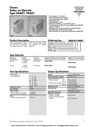
TechnicaldataDerating curvesand lossesDrive voltagelevelsDC busdesignMechanicalinstallationEMC filtersAC linereactor valuesMotor cablelengthsGeneraldataI/OSupply typesspecification OptionsFigure 2-4Outputcurrent (A)Variflex Size A 0.75kW derating curve432112kHz18kHz3kHz6kHz010 20 304050602.2 Drive LossesAmbient Temperature (EC)The following tables indicate the total drive losses at the de-rating curve points.Table 2-1 Variflex size A 0.25kW lossesLoss (W)Ambient Temperature (°C)3kHz 6kHz 12kHz 18kHz30 30 32 35 3540 30 32 35 3550 29 30 33 3255 29 29 33 31Table 2-2 Variflex size A 0.37kW lossesLoss (W)Ambient Temperature (°C)3kHz 6kHz 12kHz 18kHz30 33 33 35 3540 33 33 35 3550 29 30 33 3255 29 29 33 31Table 2-3 Variflex size A 0.55kW lossesLoss (W)Ambient Temperature (°C)3kHz 6kHz 12kHz 18kHz30 42 46 53 6140 42 43 44 4750 35 36 37 3855 31 33Variflex Technical Data 9Issue Number: 2www.carlogavazzi.com/acGross Automation (877) 268-3700 · www.carlogavazzisales.com · sales@grossautomation.com
TechnicaldataDerating curvesand lossesDrive voltagelevelsDC busdesignMechanicalinstallationEMC filtersAC linereactor valuesMotor cablelengthsGeneraldataI/OSupply typesspecification OptionsTable 2-4 Variflex size A 0.75kW lossesLoss (W)Ambient Temperature (°C)3kHz 6kHz 12kHz 18kHz30 48 50 59 6240 48 43 44 4750 35 36 37 3855 31 3310 Variflex Technical Datawww.carlogavazzi.com/ac Issue Number: 2Gross Automation (877) 268-3700 · www.carlogavazzisales.com · sales@grossautomation.com
TechnicaldataDerating curvesand lossesDrive voltagelevelsDC busdesign3 Drive voltage levelsMechanicalinstallation EMC filters AC line Motor cablereactor values lengthsGeneraldataI/OSupply typesspecification OptionsCondition 200V drives 400V drivesOV trip level 415 Vdc 830 VdcBraking level 390 Vdc 780 VdcRated upper level (AC mains +10% x 1.4142) 373 Vdc 747 VdcRated lower level (AC mains -10% x 1.4142) 255 Vdc 484 Vdc*UV reset level 215 Vdc 425 VdcUV trip level 175 Vdc 330 VdcStandard ramp voltage375 VdcEUR: 750 VdcUSA: 775 Vdc* These are the absolute minimum DC voltages that the drive can be supplied with. If the drive is not supplied with at least this voltage, it will not resetout of a UU trip at power up.Output frequency: 0 to 1500HzOutput voltage: 3 phase, 0 to drive rating (240 or 480Vac maximum set by Pr 08).Low DC bus operation (Pr 6.10)0 Low DC bus operation disabled1 Low DC bus operation enabledThe Low DC bus operation is designed to enable 3 phase 400VAC (medium voltage) Variflexs to be run off a single phase 200VAC (low voltage)supply in the event of a primary 400VAC supply failure.When the primary supply fails, the back up supply can be switched in. This will allow the drive to control the motor at a reduced power, for example tomove an elevator up or down to the next floor.There is no de-rating as such when low DC bus operation is enabled however the power will be limited by the reduced voltage and ripple generatedon the DC bus of the drive.Figure 3-1 Low DC bus operation600DC Bus (VDC)4002000When Pr 6.10 is enabled and the DC bus voltage is less than 330VDC, the drives display will flash LoAC (Low AC) to indicate that it is running off thelow voltage back up supply.NOTENThis mode is designed for use with a backup power supply and not for using a 400VAC (medium voltage) Variflex in a 200VAC (low voltage)application. As shown in the above diagram, the drives power down save parameters are saved at point 2. If the drive was to be used on a 200VACsupply, the DC bus will never fall through point 2 and power down save parameters will not be saved.Low DC bus operation voltage levels (Pr 6.10 enabled)>425VDC - normal operation
TechnicaldataDerating curvesand losses3.1 Input voltageDrive voltagelevelsDC busdesignMechanicalinstallation EMC filters AC line Motor cablereactor values lengths3.1.1 Single phase200V to 240V ±10%48Hz to 62Hz3.1.2 Three phase 200V200V to 240V ±10%48Hz to 62HzPhase imbalance 3% (between phases) or 2% negative phase sequence (IEC 146-1-1 Immunity class C)3.1.3 Three phase 400V380V to 480V ±10%48Hz to 62HzPhase imbalance 3% (between phases) or 2% negative phase sequence (IEC 146-1-1 Immunity class C)GeneraldataI/OSupply typesspecification OptionsIt is possible to run the drives on lower supply voltages than those specified above (up to -20%) but only with de-rating of the product. Running a 400Vproduct on a 230V single phase supply (at a very much reduced output power) is possible on frame sizes B & C.On products without a DC bus choke (up to 4kW), the maximum supply capacity connected to the drive without using external line chokes will be 5kAshort circuit current.12 Variflex Technical Datawww.carlogavazzi.com/ac Issue Number: 2Gross Automation (877) 268-3700 · www.carlogavazzisales.com · sales@grossautomation.com
TechnicaldataDerating curvesand lossesDrive voltagelevels4 DC bus designDC busdesignMechanicalinstallationEMC filtersAC linereactor valuesMotor cablelengthsGeneraldataI/OspecificationSupplytypesOptionsTable 4-1ModelTable 4-2Table 4-3Variflex 200V units DC bus dataDC Bus CapacitanceμFVariflex 400V units DC bus dataInrush resistorDC bus inductancemHInrush resistanceΩ at 25 o CRVFA1200025 330 22RVFA1200037 390 22RVFA1200055 660 22RVFA1200075 780 22RVFBD200110 940 44RVFBD200150 1410 44RVFCD200220 1880 66ModelDC Bus CapacitanceμFDC bus inductancemHInrush resistanceΩ at 25 o CRVFB3400037 165 44RVFB3400055 165 44RVFB3400075 165 44RVFB3400110 195 44RVFB3400150 235 44RVFC3400220 470 66RVFC3400300 470 66RVFC3400400 470 66FrameVoltagePowerRating(kW)InrushResistor(Ω)Numberin seriesEffectiveInrushResistance(Ω)PkInrushCurrent(A)A 200 0.25 22 1 22 17.9A 200 0.37 22 1 22 17.9A 200 0.55 22 1 22 17.9A 200 0.75 22 1 22 17.9B 200 1.1 22 2 44 8.9B 200 1.5 22 2 44 8.9B 400 0.37 22 2 44 17.9B 400 0.55 22 2 44 17.9B 400 0.75 22 2 44 17.9B 400 1.1 22 2 44 17.9B 400 1.5 22 2 44 17.9C 200 2.2 22 3 66 6.0C 400 2.2 22 3 66 11.9C 400 3 22 3 66 11.9C 400 4 22 3 66 11.9Variflex Technical Data 13Issue Number: 2www.carlogavazzi.com/acGross Automation (877) 268-3700 · www.carlogavazzisales.com · sales@grossautomation.com
TechnicaldataDerating curvesand lossesDrive voltagelevelsDC busdesign5 Mechanical installationMechanicalinstallation EMC filters AC linereactor valuesMotor cablelengthsGeneraldataI/OspecificationSupplytypesOptions5.1 Mechanical dimensionsFigure 5-1Size A mounting dimensionsNOTENIf DIN rail mounting is used in an installation where the drive is to be subjected to shock or vibration, it is recommended that the bottom mountingscrews are used to secure the drive to the back plate. If the installation is going to be subjected to heavy shock and vibration, then it is recommendedthat the drive is surface mounted rather than DIN rail mounted14 Variflex Technical Datawww.carlogavazzi.com/ac Issue Number: 2Gross Automation (877) 268-3700 · www.carlogavazzisales.com · sales@grossautomation.com
TechnicaldataDerating curvesand lossesDrive voltagelevelsDC busdesignMechanicalinstallation EMC filters AC linereactor valuesMotor cablelengthsGeneraldataI/OspecificationSupplytypesOptionsFigure 5-2Size B mounting dimensionsNOTENIf DIN rail mounting is used in an installation where the drive is to be subjected to shock or vibration, it is recommended that the bottom mountingscrews are used to secure the drive to the back plate. If the installation is going to be subjected to heavy shock and vibration, then it is recommendedthat the drive is surface mounted rather than DIN rail mountedVariflex Technical Data 15Issue Number: 2www.carlogavazzi.com/acGross Automation (877) 268-3700 · www.carlogavazzisales.com · sales@grossautomation.com
TechnicaldataDerating curvesand lossesDrive voltagelevelsDC busdesignMechanicalinstallation EMC filters AC linereactor valuesMotor cablelengthsGeneraldataI/OspecificationSupplytypesOptionsFigure 5-3Size C mounting dimensionsSize C is not DIN rail mountable.16 Variflex Technical Datawww.carlogavazzi.com/ac Issue Number: 2Gross Automation (877) 268-3700 · www.carlogavazzisales.com · sales@grossautomation.com
TechnicaldataDerating curvesand lossesDrive voltagelevels6 EMC filtersDC busdesignMechanicalinstallation EMC filters AC linereactor valuesMotor cablelengthsGeneraldataI/OspecificationSupplytypesOptionsEMC filters are available as optional extra parts where required.Table 6-1 EMC filtersUsed withRVFA1200025andRVFA1200037RVFA1200055andRVFA1200075RVFBD200110 toRVFBD200150RVFBD200110 toRVFBD200150RVFB3400037 toRVFB3400150NumberofphasesRVFCD200220 1RVFCD200220 3RVFC3400220 toRVFC34004006.1 Filter data111333Filter part number Filter type MountingSchaffner Standard Low leakage Footprint SideMax motorcable length (m)FS6512-12-07 Y Y Y 50mFS6512-12-07-LL Y Y Y 30mFS6512-12-07 Y Y Y 75mFS6512-12-07-LL Y Y Y 30mFS6513-20-07 Y Y YFS6513-20-07-LL Y Y YFS6513-10-07 Y Y YFS6513-10-07-LL Y Y YFS6513-10-07 Y Y YFS6513-10-07-LL Y Y YFS6514-24-07 Y Y YFS6514-24-07-LL Y Y YFS6514-14-07 Y Y YFS6514-14-07-LL Y Y YFS6514-14-07 Y Y YFS6514-14-07-LL Y Y YTable 6-2Used withRVFA1200025toRVFA1200075RVFBD200110toRVFBD200150RVFBD200110toRVFBD200150RVFB3400037toRVFB3400150EMC filter dataNumberofphases1133RVFCD200220 1RVFCD200220 3RVFC3400220toRVFC34004003Filter part numberPowerlossesat ratedcurrentIPratingWeightOperationalleakagecurrentWorstcaseleakagecurrentFilter terminaltighteningtorqueFiltercurrentratingSchaffner W Kg lb mA mA Nm lb ft AFS6512-12-07 4.1 20 0.42 0.9 25.7 49.5 0.8 0.6 12FS6512-12-07-LL 6.7 20 0.44 1.0 2.5 5 0.8 0.6 12FS6513-20-07 11.2 20 0.57 1.3 25.7 50 0.8 0.6 20FS6513-20-07-LL 12.8 20 0.64 1.4 3.6 7 0.8 0.6 20FS6513-10-07 7.5 20 0.63 1.4 40 137.2 0.8 0.6 10FS6513-10-07-LL 7.5 20 0.63 1.4 3 18.3 0.8 0.6 10FS6513-10-07 7.5 20 0.63 1.4 40 137.2 0.8 0.6 10FS6513-10-07-LL 7.5 20 0.63 1.4 3 18.3 0.8 0.6 10FS6514-24-07 16.2 20 0.84 1.9 25.7 50 0.8 0.6 24FS6514-24-07-LL 18.5 20 0.91 2.0 3.6 7 0.8 0.6 24FS6514-14-07 11.8 20 0.75 1.7 40 137.2 0.8 0.6 14FS6514-14-07-LL 11.8 20 0.74 1.6 3 18.3 0.8 0.6 14FS6514-14-07 11.8 20 0.75 1.7 40 137.2 0.8 0.6 14FS6514-14-07-LL 11.8 20 0.74 1.6 3 18.3 0.8 0.6 1418 Variflex Technical Datawww.carlogavazzi.com/ac Issue Number: 2Gross Automation (877) 268-3700 · www.carlogavazzisales.com · sales@grossautomation.com
TechnicaldataDerating curvesand losses6.2 ConformityTable 6-3Used withConformityRVFA1200025 andRVFA1200037RVFA1200055 andRVFA1200075RVFBD200110 toRVFBD200150RVFBD200110 toRVFBD200150RVFB3400037 toRVFB3400150Drive voltagelevelsNumber ofphasesRVFCD200110 1RVFCD200110 3RVFC3400220 toRVFC3400400111333DC busdesignMechanicalinstallation EMC filters AC linereactor valuesMotor cablelengthsGeneraldataI/OspecificationSupplytypesOptionsMotor cableFilter and switching frequencylengthInternal Standard Low leakagem3kHz 6kHz 12kHz 18kHz 3kHz 6kHz 12kHz 18kHz 3kHz 6kHz 12kHz 18kHz5 E2U E2U E2R E2R R I I I R I I I10 E2U E2R E2R E2R R I I I R I I I20 E2R R I I I I30 E2R I I50 E2R I5 E2U E2U E2R E2R R I I I R I I I10 E2U E2R E2R E2R R I I I R I I I20 E2R R I I I I30 E2R I I50 E2R I75 E2R I I I E2U515205080515205080515205080515205080515205080515205080Variflex Technical Data 19Issue Number: 2www.carlogavazzi.com/acGross Automation (877) 268-3700 · www.carlogavazzisales.com · sales@grossautomation.com
TechnicaldataDerating curvesand lossesDrive voltagelevelsDC busdesignMechanicalinstallation EMC filters AC linereactor valuesMotor cablelengthsGeneraldataI/OspecificationSupplytypesOptionsKey to Table 6-3 ConformityThe requirements are listed in descending order of severity, so that if a particular requirement is met then all requirements listed after it are also met.RIE2UE2RStandard Description Frequency range Limits ApplicationEN 61000-6-3(previously EN50081-1)EN 61800-3IEC 61800-3EN 61000-6-4(previously EN50081-2)EN 61800-3IEC 61800-3EN 61800-3IEC 61800-3EN 61800-3IEC 61800-3Generic emissionstandard for theresidential commercialand light - industrialenvironmentProduct standard foradjustable speed powerdrive systemsGeneric emissionstandard for theindustrial environmentProduct standard foradjustable speed powerdrive systemsProduct standard foradjustable speed powerdrive systemsProduct standard foradjustable speed powerdrive systems0.15 - 0.5MHzlimits decrease linearlywith log frequency0.5 - 5MHz5 - 30MHz66-56dBμV quasi peak56-46dBμV average56dBμV quasi peak46dBμV average60dBμV quasi peak50dBμV averageAC supplylinesRequirements for the first environment 1 , with unrestricteddistribution0.15 - 0.5MHz0.5 -30MHz79dBμV quasi peak66dBμV average73dBμV quasi peak60dBμV averageAC supplylinesRequirements for the first environment 1 with restricteddistribution 2Requirements for the second environment with unrestricteddistributionRequirements for the second environment with restricteddistribution 2Operation in this condition is not recommended1 The first environment is one where the low voltage supply network also supplies domestic premises2 When distribution is restricted, drives are available only to installers with EMC competenceCAUTIONThis caution applies where the drive is used in the first environment according to EN 61800-3.This is a product of the restricted distribution class according to IEC 61800-3. In a domestic environment thisproduct may cause radio interference in which case the user may be required to take adequate measures.NOTENWhere the drive is incorporated into a system with rated input current exceeding 100A, the higher emission limits of EN 61800-3 for the secondenvironment are applicable, and no filter is then required.NOTENOperation without an external filter is a practical cost-effective possibility in an industrial installation where existing levels of electrical noise are likelyto be high, and any electronic equipment in operation has been designed for such an environment. This is in accordance with EN 61800-3 in thesecond environment, with restricted distribution. There is some risk of disturbance to other equipment, and in this case the user and supplier of thedrive system must jointly take responsibility for correcting any problem which occurs.20 Variflex Technical Datawww.carlogavazzi.com/ac Issue Number: 2Gross Automation (877) 268-3700 · www.carlogavazzisales.com · sales@grossautomation.com
TechnicaldataDerating curvesand lossesDrive voltagelevelsDC busdesignMechanicalinstallation EMC filters AC linereactor valuesMotor cablelengthsGeneraldataI/OspecificationSupplytypesOptionsTable 6-4EMC filter dimensionsSchaffnerpart no.FS6512-12-07FS6512-12-07-LLFS6513-20-07FS6513-20-07-LLFS6513-10-07FS6513-10-07-LLFS6514-24-07FS6514-24-07-LLFS6514-14-07FS6514-14-07-LLA B C D E F H U V W X Y Z155mm(6.10in)155mm(6.10in)209mm(8.22in)209mm(8.22in)209mm(8.22in)209mm(8.22in)260mm(10.23in)260mm(10.23in)260mm(10.23in)260mm(10.23in)183.5mm(7.22in)183.5mm(7.22in)237.7mm(9.35in)237.7mm(9.35in)237.7mm(9.35in)237.7mm(9.35in)288.5mm(11.35in)288.5mm(11.35in)288.5mm(11.35in)288.5mm(11.35in)45mm(1.77in)45mm(1.77in)50mm(1.96in)50mm(1.96in)50mm(1.96in)50mm(1.96in)65mm(2.55in)65mm(2.55in)65mm(2.55in)65mm(2.55in)40mm(1.57in)40mm(1.57in)40mm(1.57in)40mm(1.57in)40mm(1.57in)40mm(1.57in)45mm(1.77in)45mm(1.77in)45mm(1.77in)45mm(1.77in)20mm(0.78in)20mm(0.78in)20mm(0.78in)20mm(0.78in)20mm(0.78in)20mm(0.78in)20mm(0.78in)20mm(0.78in)20mm(0.78in)20mm(0.78in)144mm(5.66in)144mm(5.66in)193.5mm(7.61in)193.5mm(7.61in)193.5mm(7.61in)193.5mm(7.61in)244mm(9.60in)244mm(9.60in)244mm(9.60in)244mm(9.60in)203mm(7.99in)203mm(7.99in)257.2mm(10.12in)257.2mm(10.12in)257.2mm(10.12in)257.2mm(10.12in)308mm(12.12in)308mm(12.12in)308mm(12.12in)308mm(12.12in)16AWG M4 75mm(2.95in)16AWG M4 75mm(2.95in)14AWG M4 80mm(3.15in)14AWG M4 80mm(3.15in)14AWG M4 80mm(3.15in)14AWG M4 80mm(3.15in)12AWG M4 94mm(3.70in)12AWG M4 94mm(3.70in)16AWG M4 94mm(3.70in)16AWG M4 94mm(3.70in)M4M4M4M4M4M4M4M4M4M48.7mm(0.34in)8.7mm(0.34in)8.7mm(0.34in)8.7mm(0.34in)8.7mm(0.34in)8.7mm(0.34in)8.7mm(0.34in)8.7mm(0.34in)8.7mm(0.34in)8.7mm(0.34in)4.5mm(0.17in)4.5mm(0.17in)4.5mm(0.17in)4.5mm(0.17in)4.5mm(0.17in)4.5mm(0.17in)4.5mm(0.17in)4.5mm(0.17in)4.5mm(0.17in)4.5mm(0.17in)Variflex Technical Data 21Issue Number: 2www.carlogavazzi.com/acGross Automation (877) 268-3700 · www.carlogavazzisales.com · sales@grossautomation.com
TechnicaldataDerating curvesand lossesDrive voltagelevelsDC busdesignMechanicalinstallation7 AC line reactor valuesEMC filtersAC line Motor cablereactor values lengthsGeneraldataI/OspecificationSupplytypesOptionsTable 7-1AC line reactor values7.1 Line reactorsInput line reactors reduce the risk of damage to the drive resulting from poor phase balance or severe disturbances on the supply network.Where line reactors are to be used, reactance values of approximately 2% are recommended. Higher values may be used if necessary, but may resultin a loss of drive output voltage because of voltage drop. This may reduce torque at high speed.For all drive ratings, 2% line reactors permit drives to be used with a supply imbalance of up to 3.5% negative phase sequence (equivalent to 5%voltage imbalance between phases).A line reactor should be connected in each phase of the supply. Each drive should have its own line reactor. Three individual reactors or a single threephase reactor can be used. Single phase drives only require one single phase line reactor.Severe disturbances may be caused by the following factors:• Power factor correction equipment connected close to the drive• Large DC drives having no or inadequate line reactors connected to the supply• Direct-on-line started motor(s) connected to the supply such that when any of these motors are started, the voltage dip exceeds 20%.• Supply capacity exceeds 200kVA• Fault current exceeds 5kASuch disturbances may cause excessive peak currents to flow in the input power circuit of the drive. This may cause nuisance tripping and in extremecases, failure of the drive.Low power drives may also be susceptible to disturbance when connected to supplies with high rated capacity.NNOTERFI filters (for EMC purposes) do not give adequate protection against these conditions.7.2 Reactor current ratingsContinuousrms currentPeakcurrentDrives used withReactor part Input InductanceWeight Dimensionsnumber phasesmH A A Kg L D HRVFA1200025 4402-0224 1 2.25 6.5 13 0.8 72 65 90RVFA1200037 4402-0224 1 2.25 6.5 13 0.8 72 65 90RVFA1200055 4402-0225 1 1.0 15.1 30.2 1.1 82 75 100RVFA1200075 4402-0225 1 1.0 15.1 30.2 1.1 82 75 100RVFBD200110 4402-0225 1 1.0 15.1 30.2 1.1 82 75 100RVFBD200150 4402-0226 1 0.5 26.2 52.4 1.5 82 90 105RVFCD200220 4402-0226 1 0.5 26.2 52.4 1.5 82 90 105RVFBD200110 4402-0227 3 2.0 7.9 15.8 3.5 150 90 150RVFBD200150 4402-0228 3 1.0 15.4 47.4 3.8 150 90 150RVFCD200220 4402-0228 3 1.0 15.4 47.4 3.8 150 90 150RVFB3400037 4402-0227 3 2.0 7.9 15.8 3.5 150 90 150RVFB3400055 4402-0227 3 2.0 7.9 15.8 3.5 150 90 150RVFB3400075 4402-0227 3 2.0 7.9 15.8 3.5 150 90 150RVFB3400110 4402-0227 3 2.0 7.9 15.8 3.5 150 90 150RVFB3400150 4402-0227 3 2.0 7.9 15.8 3.5 150 90 150RVFC3400220 4402-0228 3 1.0 15.4 47.4 3.8 150 90 150RVFC3400300 4402-0228 3 1.0 15.4 47.4 3.8 150 90 150RVFC3400400 4402-0228 3 1.0 15.4 47.4 3.8 150 90 150Continuous current:Not less than the continuous input current rating of the drive.Repetitive peak current rating:Not less than twice the continuous input current rating of the drive.Voltage fluctuation (Flicker) standard EN61000-3-3 (IEC61000-3-3)Those models that fall within the scope of EN61000-3-3, as stated in the declaration of Conformity, conform to the requirements for manual switching,i.e. the voltage dip caused when a drive at room temperature is switched on is within the permitted limits.The drive does not of itself cause periodic voltage fluctuation in normal operation. The installer must ensure that the control of the drive is such thatperiodic fluctuations in supply current do not infringe the flicker requirements where applicable. Note that large periodic load fluctuations in thefrequency range of between 1Hz and 30Hz are particularly inclined to cause irritating lighting flicker and are subject to stringent limits underEN61000-3-3.22 Variflex Technical Datawww.carlogavazzi.com/ac Issue Number: 2Gross Automation (877) 268-3700 · www.carlogavazzisales.com · sales@grossautomation.com
TechnicaldataDerating curvesand lossesDrive voltagelevelsDC busdesignMechanicalinstallationEMC filtersAC line Motor cablereactor values lengthsGeneraldataI/Ospecification7.3 Input line reactors for harmonics standards EN61000-3-2 and IEC61000-3-2The following input line reactors allow the Variflex 0.25 - 0.55kW drives to conform to harmonic standards EN61000-3-2 and IEC61000-3-2.Table 7-2 Input line reactors for harmonics standards EN61000-3-2 and IEC61000-3-2DriveInputReactor part Drive powerInductancepowerContinuousnumber de-ratingrms currentW mHRVFA12200025 4400-0239 None 374 4.5 2.4RVFA12200037 4400-0238 None 553 9.75 3.2RVFA12200055 4400-0237 18% 715 16.25 4.5EN61000-3-2 and IEC61000-3-2 applies to equipment with a supply voltage of 230VAC and a line current up to 16A, single or three phase.Professional equipment with rated input power exceeding 1kW has no limits - this applies to the 0.75kW drive.Further information on EN61000-3-2 and IEC61000-3-2 is included on the EMC data sheets available from your local <strong>Carlo</strong> <strong>Gavazzi</strong> representative orDistributor.7.4 Voltage fluctuation (Flicker) standard EN61000-3-3 (IEC61000-3-3)Those models which fall within the scope of EN61000-3-3, as stated in the Declaration of Conformity, conform to the requirements for manualswitching, i.e. the voltage dip caused when a drive at room temperature is switched on is within the permitted limits.The drive does not of itself cause periodic voltage fluctuation in normal operation. The installer must ensure that the control of the drive is such thatperiodic fluctuations in supply current do not infringe the flicker requirements where applicable. Note that large periodic load fluctuations in thefrequency range of between 1Hz and 30Hz are particularly inclined to cause irritating lighting flicker and are subject to stringent limits underEN61000-3-3.Figure 7-1 Input line reactor 4402-0224SupplytypesOptionsAll dimensions in mmVariflex Technical Data 23Issue Number: 2www.carlogavazzi.com/acGross Automation (877) 268-3700 · www.carlogavazzisales.com · sales@grossautomation.com
TechnicaldataDerating curvesand lossesDrive voltagelevelsDC busdesignMechanicalinstallationEMC filtersAC line Motor cablereactor values lengthsGeneraldataI/OspecificationSupplytypesOptionsFigure 7-2 Input line reactor 4402-0225All dimensions in mmFigure 7-3 Input line reactor 4402-0226All dimensions in mm24 Variflex Technical Datawww.carlogavazzi.com/ac Issue Number: 2Gross Automation (877) 268-3700 · www.carlogavazzisales.com · sales@grossautomation.com
TechnicaldataDerating curvesand lossesDrive voltagelevelsDC busdesignMechanicalinstallationEMC filtersAC line Motor cablereactor values lengthsGeneraldataI/OspecificationSupplytypesOptionsFigure 7-4 Input line reactor 4402-0227All dimensions in mmFigure 7-5 Input line reactor 4402-0228All dimensions in mmVariflex Technical Data 25Issue Number: 2www.carlogavazzi.com/acGross Automation (877) 268-3700 · www.carlogavazzisales.com · sales@grossautomation.com
TechnicaldataDerating curvesand lossesDrive voltagelevelsDC busdesignMechanicalinstallationEMC filtersAC line Motor cablereactor values lengthsGeneraldataI/OspecificationSupplytypesOptionsFigure 7-6 Input line reactor 4402-0229All dimensions in mm26 Variflex Technical Datawww.carlogavazzi.com/ac Issue Number: 2Gross Automation (877) 268-3700 · www.carlogavazzisales.com · sales@grossautomation.com
TechnicaldataDerating curvesand lossesDrive voltagelevelsDC busdesign8 Motor cable lengthsMechanicalinstallationEMC filtersAC line reactorvaluesMotor cablelengthsGeneraldataI/OspecificationSupplytypesOptionsTable 8-1Motor cable lengthsDrive frame size kW rating Maximum motor cable lengthABC0.25 and 0.37 50m0.55 and 0.75 75m100m100mThe capacitive loading of the drive by the motor cable means that the cable length limits shown in table 8-1 must be observed. Failure to do so canresult in spurious OI.AC tripping of the drive. If longer cable lengths are required, consult your local <strong>Carlo</strong> <strong>Gavazzi</strong> representative or Distributor.The maximum cable lengths were measured using cable with capacitance of 130pF/m.This capacitance was measured by taking one phase as one node and the screen (shield) and earth (ground) (if any) as the other node, thenmeasuring the capacitance between the two points.VariflexTechnical Data 27Issue Number: 2www.carlogavazzi.com/acGross Automation (877) 268-3700 · www.carlogavazzisales.com · sales@grossautomation.com
TechnicaldataDerating curvesand lossesDrive voltagelevels9 General dataDC busdesignMechanicalinstallationEMC filtersAC line reactorvaluesMotor cablelengthsGeneraldataI/OspecificationSupplytypesOptions9.1 Ratings9.1.1 IP ratingIP20• The drive complies with the requirements of IP20 as standard.IP4X• The top surface of the drive complies with the requirements of IP4X with the optional top cover fitted.First digit: Protection against contact and ingress of foreign bodies.2 - Protection against medium size foreign bodies ∅> 12mm (finger)Second digit: protection against ingress of water.0 - No protection9.2 Input phase imbalance3% between phases or 2% negative phase sequence.9.3 Ambient temperature-10°C (14°F) to 40°C (104°F) at 3kHzOperation up to 55°C (131°F) with de-rating.(see de-rating curves for further information)NNOTEThe drive can be powered up and run at a minimum temperature of -10°C (14°F).9.4 Storage temperature-40 to +60°C (-40 to +140°F) for 12 months max9.5 AltitudeRated altitude: 1000m (3250 ft)Reduce the normal full load current by 1% for every 100m (325 ft) above 1000m (3250 ft) up to a maximum of 3000m (9750 ft).9.6 HumidityMaximum relative humidity 95% (non-condensing).9.7 Storage humidityMaximum relative humidity 93%, 40°C, 4 days.9.8 Pollution degreeDesigned for operation in Pollution degree 2 environments (dry, non-conductive contamination only)9.9 Materials9.10 Vibration9.10.1 RandomStandard: In accordance with IEC68-2-64 and IEC68-2-36: Test FhSeverity: 1.0 m 2 /s 3 (0.01g 2 /Hz) ASD from 5 to 20Hz, -3dB/octave from 20 to 200HzDuration: 30 minutes in each of 3 mutually perpendicular axes.9.10.2 SinusiodalStandard: IEC68-2-6: Test FcFrequency range: 2 to 500HzSeverity: 3.5mm peak displacement from 2 to 9Hz10m/s 2 peak displacement from 9 to 200Hz15m/s 2 peak displacement from 200 to 500HzSweep rate: 1 octave/minuteDuration: 15 minutes in each of 3 mutually perpendicular axes.9.10.3 BumpStandard: IEC68-2-29: Test EbSeverity: 18g, 6ms, half sineNumber of bumps: 600 (100 in each direction of axes)28 Variflex Technical Datawww.carlogavazzi.com/ac Issue Number: 2Gross Automation (877) 268-3700 · www.carlogavazzisales.com · sales@grossautomation.com
TechnicaldataDerating curvesand lossesDrive voltagelevels9.11 Frequency accuracy0.01%9.12 Resolution0.1HzDC busdesign9.13 Output frequency range0 to 1500Hz9.14 Starts per hourMechanicalinstallationEMC filtersAC line reactorvaluesMotor cablelengthsGeneraldataI/OspecificationElectric startsWith the supply permanently connected the number of electronic motor starts per hour is only limited by motor and drive thermal limits.Power startsThe number of starts by connection of the ac supply is limited. The start up circuit will allow for three consecutive starts at 3-second intervals on initialpower up. Exceeding the rated number of starts per hour, presented in the table below, could result in damage to the start up circuit.Drive frame sizeMaximum AC line starts per hourevenly spaced in timeA, B & C 20SupplytypesOptions9.15 Start-up timeThe soft-start circuit must charge the dc bus and SMPS outputs and stabilise to allow the control processor to start operation in the following times:-Drive frame sizeMaximum time taken to charge DC busand SMPS outputs to stabiliseA, B & C 1s9.16 Serial communicationsModbus RTU9.17 Switching frequenciesThe software allows for the following switching frequencies:Size A & B: 3, 6, 12, 18kHzSize C: 3, 6, 12kHz9.18 HarmonicsThe Variflex industrial AC variable speed drives are classified as class A professional equipment as defined in EN61000-3-2: 1995. Drives with inputpower equal to or below 1kW that do not meet the requirements of EN61000-3-2 are to be corrected, to ensure compliance, at the point of installationusing suitable AC line chokes. See 7.2 (Reactor current ratings)9.19 Acoustic noiseFrame Power ratings Condition Max SPL measurement (dBA)A All ratings N/A None contributed by drive (no fan).B ≤0.75kW N/A None contributed by drive (no fan).B ≥1.1kW rd mode, fan on 50C All ratings rd mode, fan on 53VariflexTechnical Data 29Issue Number: 2www.carlogavazzi.com/acGross Automation (877) 268-3700 · www.carlogavazzisales.com · sales@grossautomation.com
TechnicaldataDerating curvesand lossesDrive voltagelevelsDC busdesign10 I/O specificationMechanicalinstallationEMC filtersAC linereactor valuesMotor cablelengthsGeneraldataI/OspecificationSupplytypesOptionsThe control circuits are isolated from the power circuits in the drive by basic insulation (single insulation) only. The installer must ensurethat the external control circuits are insulated from human contact by at least one layer of insulation (supplementary insulation) rated foruse at the AC supply voltage.If the control circuits are to be connected to other circuits classified as Safety Extra Low Voltage (SELV) (e.g. to personal computer), anadditional isolating barrier must be included in order to maintain the SELV classification.T10V commonT2Voltage : Current inputParameter rangeScalingInput impedanceAnalog input 1 (A1), either voltage or currentResolution 0.1%Accuracy ± 2%Sample timeAbsolute maximum voltage range0 to 10V : mA as parameter range4-20, 20-4, 0-20, 20-0, 4-.20, 20-.4, VoltInput range automatically scaled to Pr 01 (Minimum setspeed) to Pr 02 (Maximum set speed)200Ω (current) : 100kΩ (voltage)6ms+35V to -18V with respect to 0V commonT3 +10V reference outputMaximum output current5mAProtectionTolerates continuous short circuit to 0VAccuracy ± 2%T4Analog input 2 (A2), either voltage or digital inputVoltage : Digital input 0 to +10V : 0 to +24VScaling (as voltage input)Input impedanceResolution 0.1%Accuracy ± 2%Sample timeNominal threshold voltageAbsolute maximum voltage rangeInput range automatically scaled to Pr 01 Minimum setspeed / Pr 02 Maximum set speed100kΩ (voltage) : 6k8 (digital input)6ms+10V (positive logic only)+35V to -18V with respect to 0V commonT5T6Voltage ratingCurrent ratingContact isolationUpdate timeOperation of contactStatus relay - Drive healthy (Normally open)240Vac30DC2A6A resistive1.5kVac (over voltage category II)1.5msOPEN- AC supply removed from drive.- AC supply applied to drive with drive in tripped condition.CLOSED- AC supply applied to drive with drive in a 'ready to run' or'running' condition (not tripped)30 Variflex Technical Datawww.carlogavazzi.com/ac Issue Number: 2Gross Automation (877) 268-3700 · www.carlogavazzisales.com · sales@grossautomation.com
TechnicaldataDerating curvesand lossesDrive voltagelevelsDC busdesignMechanicalinstallationEMC filtersAC linereactor valuesMotor cablelengthsGeneraldataI/OspecificationSupplytypesOptionsProvide fuse or other over-current protection in status relay circuit.B1 Analog voltage output - Motor speedVoltage output 0 to +10VScaling0V represents 0Hz/rpm output+10V represents the value in Pr 02, maximum set speedMaximum output current5mAResolution 0.1%Accuracy ± 5%Update time6msProtectionTolerates continuous short circuit to 0VB2 +24V outputMaximum output current100mAProtectionTolerates continuous short circuit to 0VAccuracy ± 15%B3 Digital output - Zero speedVoltage range 0 to +24VMaximum output current50mA at +24V (current source)Output impedance6.8kΩUpdate time1.5msAbsolute maximum voltage range +35V to -1V with respect to 0V commonNOTENThe total available current from the digital output plus the +24V output is 100mAB4B5B6B7NIf the drives enable terminal is opened, the drives output is disabled and the motor will coast to a stop. The drive will not re-enable for 0.5s after theenable terminal is closed again.10.1 Drive resetDigital Input - Enable/Reset */**Digital Input - Run Forward **Digital Input - Run Reverse **Digital Input - Local/Remote speed reference select (A1/A2)Positive logic onlyLogicVoltage range 0 to +24VInput impedance6.8kΩSample time1.5msNominal threshold voltage +10VAbsolute maximum voltage range +35V to -18V with respect to 0V commonNOTEIf the enable terminal is opened, the drive’s output is disabled and the motor will coast to a stop. The drive will not re-enable for 1.0s after the enableterminal is closed again.*Following a drive trip, opening and closing the enable terminal will reset the drive. If the run forward or run reverse terminal is closed, the drive willrun straight away.**Following a drive trip and a reset via the stop/reset key, the enable, run forward or run reverse terminals will need to be opened and closed to allowthe drive to run. This ensures that the drive does not run when the stop/reset key is pressed.The enable, run forward and run reverse terminals are level triggered apart from after a trip where they become edge triggered. See * and ** above.If the enable and run forward or enable and run reverse terminals are closed when the drive is powered up, the drive will run straight away up to a setspeed.If both the run forward and run reverse terminals are closed, the drive will stop under the control of the ramp and stopping modes set in Pr 30 andPr 31Variflex Technical Data 31Issue Number: 2www.carlogavazzi.com/acGross Automation (877) 268-3700 · www.carlogavazzisales.com · sales@grossautomation.com
TechnicaldataDerating curvesand lossesDrive voltagelevels10.2 Sample/update timesDC busdesignMechanicalinstallationEMC filtersAC linereactor valuesMotor cablelengthsGeneraldataI/OspecificationThe sample/update times shown in the control terminal specification within the Variflex Technical Guide are the default sample/update times for thedefault terminal set-up. The sample/update time depends on the destination/source parameter of the digital or analog inputs/outputs.These sample/update times are the sample or update times for the control microprocessor. The actual sample/update time maybe slightly longer dueto the design of the Variflex.10.3 Task routine timesAt the beginning of each menu, there is a single line parameter description and this contains the update rate for each parameter. This time signifiesthe task routine time in the software that the parameter is updated on. For a background task, the time depends on processor loading i.e. whatfunctions the drive is carrying out and what advanced menus are being used.Update rate Microprocessor update time Comments2ms 2ms Updated every 2ms5ms 5ms Updated every 5ms21ms 21ms Updated every 21ms128ms 128ms Updated every 128msReset N/A Destination/source parameter changed on a ResetBBRBWBackgroundBackground readBackground writeUpdated as a background task. Update rate dependson processor loading.SupplytypesOptionsFrom practical tests carried out:Condition Minimum Maximum AverageTime for drive to respond to a run command 4.1ms 5.62ms 5.02msTime for the drive to respond to a stop command 2.82ms 3.94ms 3.31msTime for the drive to respond to a step change in analog input voltage7.93ms32 Variflex Technical Datawww.carlogavazzi.com/ac Issue Number: 2Gross Automation (877) 268-3700 · www.carlogavazzisales.com · sales@grossautomation.com
TechnicaldataDerating curvesand lossesDrive voltagelevels11 Supply typesDC busdesignMechanicalinstallationEMC filtersAC linereactor valuesMotor cablelengthsGeneraldataI/OspecificationSupplytypesOptionsVariflex is suitable for use with any supply type, i.e. TN-S, TN-C-S, TT, IT, with a grounding at any potential, i.e. neutral, centre or corner ('groundeddelta').Drives are suitable for use on supplies of installation category III and lower, according to IEC60664-1. This means they may be connectedpermanently to the supply at its origin in a building, but for outdoor installation, additional over-voltage suppression (transient voltage surgesuppression) must be provided to reduce category IV to category III.11.1 AC supply requirementsSingle phase drivesSingle phase - Between one phase and neutral of a star connected three phase supply.- Between two phases of a three phase supply.Three phase modelsThree-phase star or delta supply of the correct voltage.Dual rated modelsAny of the above supplies can be used.11.2 SafetyElectric shock riskThe voltages present in the following locations can cause severe electric shock and may be lethal:• AC supply cables and connections• DC and brake cables and connections• Output cables and connections• Many internal parts of the drive, and external option unitsUnless otherwise indicated, control terminals are single insulated and must not be touched.Isolation deviceThe AC supply must be disconnected from the drive using an approved isolation device before any cover is removed from the drive orbefore any servicing work is performed.STOP functionThe STOP function does not remove dangerous voltages from the drive, the motor orany external option units.Stored chargeThe drive contains capacitors that remain charged to a potentially lethal voltage after the AC supply has been disconnected. If the drivehas been energized, the AC supply must be isolated at least ten minutes before work may continue.Normally, the capacitors are discharged by an internal resistor. Under certain, unusual fault conditions, it is possible that the capacitorsmay fail to discharge, or be prevented from being discharged by a voltage applied to the output terminals. If the drive has failed in amanner that causes the display to go blank immediately, it is possible the capacitors will not be discharged. In this case, consult <strong>Carlo</strong><strong>Gavazzi</strong> or their authorized distributor.Equipment supplied by plug and socketSpecial attention must be given if the drive is installed in equipment which is connected to the AC supply by a plug and socket. The ACsupply terminals of the drive are connected to the internal capacitors through rectifier diodes which are not intended to give safetyisolation. If the plug terminals can be touched when the plug is disconnected from the socket, a means of automatically isolating the plugfrom the drive must be used (e.g. a latching relay).11.3 CablesRecommended cable sizes are given in tables 1-2 & 1-7. They are only a guide; refer to local wiring regulations for correct size of cables. In somecases, a larger cable size is required to avoid excessive voltage drop.Use 105°C (221°F) (UL 60/75°C temp rise) PVC-insulated cable with copper conductors having a suitable voltage rating, for the following powerconnectors:• AC supply to external EMC filter (when used)• AC supply (or external EMC filter) to drive• Drive to motor• Drive to braking resistorVariflexTechnical Data 33Issue Number: 2www.carlogavazzi.com/acGross Automation (877) 268-3700 · www.carlogavazzisales.com · sales@grossautomation.com
TechnicaldataDerating curvesand lossesDrive voltagelevelsDC busdesignMechanicalinstallationEMC filtersAC linereactor valuesMotor cablelengthsGeneraldataI/OspecificationMotor cablesThe recommended output cable sizes assume that the motor maximum current matches that of the drive. Where a motor of reduced rating is used,the cable rating may be chosen to match that of the motor. To ensure that the motor and cable are protected against overload, the drive must beprogrammed with the correct motor rated voltage.11.4 FusesThe AC supply to the drive must be fitted with suitable protection against overload and short circuits. Tables 1-2 & 1-7 show the recommended fuseratings. Failure to observe this requirement will cause risk of fire.A fuse or other protection device must be included in all live connectors to the AC supply.An MCB (miniature circuit breaker) or MCCB (moulded case circuit breaker) with type C tripping characteristics maybe used in place of fuses as longas the fault clearing capacity is sufficient for the installation.Fuse typesEurope: Type gG HRC fuses complying with EN60269 parts 1 and 2 (BS88)USA: Bussman Limitron KTK series, class CC fast acting fuses up to 30A, class J above 30A.11.5 Ground connectionsThe drive must be connected to the system ground of the AC supply. The ground wiring must conform to local regulations and codes of practice.The ground loop impedance must conform to the requirements of local safety regulations. The ground connections must be inspected and tested atappropriate intervals.Use of RCDs - residual current deviceThere are three common types of RCD/ELCBType AC - detects AC fault currentsType A - detects AC and pulsating DC fault currents (provided the DC current reaches zero at least once every half cycle)Type B - detects AC, pulsating DC, and smooth DC fault currents• Type AC should never be used with inverter drives• Type A can only be used with single phase drives• Type B must be used with three phase drives.It is recommended that only Type B RCDs be used with inverter drivesIf an external EMC filter is used, a delay of at least 50ms should be incorporated in the RCD to ensure spurious trips are not seen. The leakagecurrent is likely to exceed the trip level if all of the phases are not energised simultaneously.11.6 Ground leakageThe ground leakage current depends upon the internal EMC filter is fitted. The drive is supplied with the filter fitted. Instructions for removal of theinternal EMC filter are given in Section 4.3.1 of the getting started guide.With internal EMC filter fittedSize A10mA AC at 230V, 50Hz (proportional to supply voltage and frequency)Size B and C1 phase 200V product20mA AC at 230V, 50Hz (proportional to supply voltage and frequency)3-phase 200V product7mA AC at 230V, 50Hz (proportional to supply voltage and frequency)3-phase 400V product8.2mA AC at 415V, 50Hz (proportional to supply voltage and frequency)30uA DC (10Ω)NOTE NThe above leakage currents are just the leakage currents of the drive with the internal EMC filter connected and do not take into account any leakagecurrents of the motor or motor cable.With internal EMC filter removed
TechnicaldataDerating curvesand lossesDrive voltagelevelsDC busdesignMechanicalinstallationEMC filtersAC linereactor valuesMotor cablelengthsGeneraldataI/Ospecification11.7 Use of earth leakage circuit breakers (ELCB)/residual current device (RCD)There are three common types of ELCB/RCD:Type AC - detects AC fault currentsType A - detects AC and pulsating DC fault currents (provided the DC current reaches zero at least once every half cycle)Type B - detects AC, pulsating DC and smooth DC fault currents• Type AC should never be used with drives• Type A can only be used with single phase drives• Type B must be used with three phase drivesSupplytypesOptionsVariflexTechnical Data 35Issue Number: 2www.carlogavazzi.com/acGross Automation (877) 268-3700 · www.carlogavazzisales.com · sales@grossautomation.com
TechnicaldataDerating curvesand losses12 OptionsDrive voltagelevelsDC busdesignMechanicalinstallationEMC filtersAC linereactor valuesMotor cablelengthsGeneraldataI/OspecificationSupplytypesOptionsAll Variflex Solutions Modules are colour-coded, in order to make identification easy. The following table shows the colour-code key and gives furtherdetails on their function.* Only used on sizes B & C (not compatible with size A)Type Option Colour Name Further detailsPurple SM-PROFIBUS-DPPROFIBUS-DP optionPROFIBUS-DP adapter for communication with VariflexMediumGreySM-DeviceNetDeviceNet optionDeviceNet adapter for communication with VariflexFieldbus*DarkGreySM-INTERBUSINTERBUS optionINTERBUS adapter for communication with VariflexLightGreySM-CANopenCANopen optionCANopen adapter for communication with VariflexBeigeSM-EthernetEthernet optionEthernet adapter for communication with VariflexExtended IODarkYellowDark RedSM-I/O LiteSM-I/O TimerI/O Lite optionIncreases the I/O capability by adding the following to the existing I/O in thedrive:• ±10V bi-polar / 4-20mA analog input• 1.0-10V / 4-20mA analog output• Digital inputs x 3• Encoder speed reference input (A, /A, B, /B)• Relay x 1Timer I/O optionSame features is I/O Lite, but with the addition of a battery backed-up realtime clock.TurquoiseSM-PELVPELV optionIsolated digital I/O to NAMUR NE37 (for chemical industry).BlackSmartStickSmartStick optionUpload drive parameters to the SmartStick for storage or for easy set-up ofidentical drives or downloading to replacement drivesAutomationWhiteLogicStickLogicStick optionThe LogicStick plugs into the front of the drive and enables the user toprogram PLC functions within the drive.(The LogicStick can also be used as a SmartStick)SM-Keypad PlusLCD keypad display optionRemote panel mounting LCD multilingual text keypad display to IP54 (NEMA12) with additional help keyKeypadKeypad RemoteLED keypad display optionRemote panel mounting LED display to IP54 (NEMA 12) with additionalfunction key36 Variflex Technical Datawww.carlogavazzi.com/ac Issue Number: 2Gross Automation (877) 268-3700 · www.carlogavazzisales.com · sales@grossautomation.com
TechnicaldataDerating curvesand lossesDrive voltagelevelsDC busdesignMechanicalinstallationEMC filtersAC linereactor valuesMotor cablelengthsGeneraldataI/OspecificationSupplytypesOptionsType Option Colour Name Further detailsEMC FiltersThese additional filters are designed to operate together with the drive’s ownintegral EMC filter in areas of sensitive equipmentEMCAC input linereactorsTo reduce supply harmonicsBracketCable management bracketCablemanagementUL type 1 kitBottom metal gland plate, top cover and side covers to allow the drive tocomply with the requirements of UL type 1Top coverTop cover kitThe additional top cover kit will increase the environmental protection of thetop face to IP4X in vertical direction.CommunicationsCG Comms cableCGSoftSyPTLiteCable with isolation RS232 to RS485 converter. For connecting PC/Laptopto the drive when using CTSoft or SyPTLiteSoftware for PC or Laptop which allows the user to commission and storeparameter settingsSoftware for PC or Laptop which allows the user to program PLC functionswithin the drive12.1 Top cover kitThe Top Cover kit will comprise of a top cover which will clip to the top of the drives plastic housing. This Top Cover will stop falling dirt or debris fromentering the electronics through the ventilation slots on the top of the drive. This will allow the top of the drive comply with the requirements of IP4X.When the Top Cover is fitted, the drive must still be mounted in a location which prevents access except by trained and authorisedpersonnel, and which prevents the ingress of harmful contamination. It is designed for use in an environment classified as pollutiondegree 2 in accordance with IEC 60664-1. This means only dry, non-conducting contamination is acceptable.12.2 UL Type 1 KitThe UL Type 1 kit will allow the drive to comply with the requirements of UL Type 1.The UL Type 1 Kit will comprise of the following parts:Variflex Size A• 1 x Conduit entry kit• 1 x Top Cover• 1 x Side CoverVariflex Size B• 1 x Conduit entry kit• 1 x Top Cover• 4 x Side CoverVariflex size C• 1 x Conduit entry kit• 1 x Top Cover• 5 x Side CoverVariflex Technical Data 37Issue Number: 2www.carlogavazzi.com/acGross Automation (877) 268-3700 · www.carlogavazzisales.com · sales@grossautomation.com
0472-0031-02Gross Automation (877) 268-3700 · www.carlogavazzisales.com · sales@grossautomation.com