Differential Output Terminations LVPECL, HCSL, LVDS ... - SiTime
Differential Output Terminations LVPECL, HCSL, LVDS ... - SiTime
Differential Output Terminations LVPECL, HCSL, LVDS ... - SiTime
- No tags were found...

You also want an ePaper? Increase the reach of your titles
YUMPU automatically turns print PDFs into web optimized ePapers that Google loves.
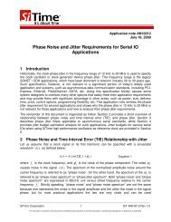
<strong>Output</strong> <strong>Terminations</strong> for SiT9102/9002/9103<strong>LVPECL</strong>, <strong>LVDS</strong>, CML, and <strong>HCSL</strong> differential driversoscillators are enhanced from 16 mA to 22 mA, thus increasing the signal swing for a 25Ω loadfrom 400 mV to 550 mV.2.2 <strong>LVPECL</strong>0 <strong>Output</strong>VDDChipboundaryI SW= 22mAOUT+OUT-Figure 6: <strong>LVPECL</strong>0 driver output structureThe <strong>LVPECL</strong>0 driver output structure is shown in Figure 6. The <strong>LVPECL</strong>0 switched current,ISW, is 22mA. This effectively increases the outputs’ switching drive capacity from the<strong>LVPECL</strong>1 mode’s 16mA to 22mA. One use of this mode is for <strong>LVPECL</strong> with an AC-coupledtermination circuit, as described below.An AC-coupled termination is often recommended when the <strong>LVPECL</strong> output drives a differentialreceiver with a termination voltage different from what the driver needs. As shown in Figure 7, acapacitor is used to block the DC path to the load termination and receiver, allowing the receiverto set its own termination voltage. In this example, the receiver inputs are biased by a 50Ωresistor to a termination voltage, which is determined by the receiver requirements. Since thecapacitor blocks the DC path for the driver’s outputs, additional 150Ω resistors are installedbetween the outputs and ground at the source to provide the required output DC current paths.From the AC standpoint, the R1/R2 resistors at the source are in parallel with the 50Ω resistorsat the load, resulting in a 37.5Ω equivalent load to the driver. To obtain the nominal <strong>LVPECL</strong>signal swings at the load, the user should choose the <strong>LVPECL</strong>0 output mode of SiT9102 with 22mA current drivers, thus increasing the nominal signal swing to 825 mV.Figure 7: <strong>LVPECL</strong>0 in load terminated AC-coupled application--------------------------------------------------------------------------------------------------------------------------------------------The Smart Timing Choice 6 SiT-AN10009 Rev 1.3