DIGI KEYER II - microHAM
DIGI KEYER II - microHAM
DIGI KEYER II - microHAM

Create successful ePaper yourself
Turn your PDF publications into a flip-book with our unique Google optimized e-Paper software.
<strong>microHAM</strong> © 2010 All rights reserved<strong>DIGI</strong> <strong>KEYER</strong> <strong>II</strong><strong>microHAM</strong>fax: +421 2 4594 5100e-mail: support@microham.comhomepage: www.microham.comVersion 7.95 Decenber, 20101
<strong>microHAM</strong> © 2010 All rights reservedTABLE OF CONTENTSCHAPTERPAGE1. FEATURES AND FUNCTIONS ......................................................................................................... 32. IMPORTANT WARNINGS ................................................................................................................ 43. PANEL DESCRIPTION ..................................................................................................................... 5Front Panel .................................................................................................................. 5Rear Panel ................................................................................................................... 64. INSTALLATION ................................................................................................................................ 7Preparing for Use................................................................................................................. 7Macintosh (OS X) Installation............................................................................................... 8Windows (Windows XP, Vista, 7) Installation ....................................................................... 9Installing <strong>microHAM</strong> USB Device Router...................................................................... 9Configuring <strong>microHAM</strong> CODEC ................................................................................. 10Configuring <strong>microHAM</strong> USB Device Router ............................................................... 11Creating and Using Virtual Ports ................................................................................ 125. <strong>microHAM</strong> USB DEVICE ROUTER ............................................................................................... 13Menu: Router .............................................................................................................. 13Menu: Preset .............................................................................................................. 14Menu: Device ............................................................................................................. 15Menu: Virtual Port ....................................................................................................... 16Menu: Help ................................................................................................................. 17Device Configuration .................................................................................................. 17Ports Tab............................................................................................................... 18CAT& 2 nd CAT ............................................................................................... 19FSK & 2 nd FSK ............................................................................................. 21CW ................................................................................................................ 23PTT & 2 nd PTT .............................................................................................. 23Foot Switch ................................................................................................... 24Squelch ......................................................................................................... 24WinKey...........................................................................................................25Control............................................................................................................25Audio Tab.............................................................................................................. 26Audio Mixer ......................................................................................................... 27PTT Tab.................................................................................................................29CW & WinKey Tab ................................................................................................31CW Messages Tab ................................................................................................32FSK Messages Tab ...............................................................................................33Keyboard Tab ........................................................................................................34System Settings Tab .............................................................................................356. SETTING AUDIO LEVELS ............................................................................................................. 357. EXTERNAL KEYBOARD/KEYPAD ................................................................................................ 388. SYSTEM CONSIDERATIONS ........................................................................................................ 409. PACKAGE CONTENTS .................................................................................................................. 4010. WARRANTY .................................................................................................................................... 4111. SPECIFICATIONS ........................................................................................................................... 42Declaration of Conformity ......................................................................................................... 43APPENDIX A – CONNECTORS ............................................................................................... 44APPENDIX B – RFI Considerations ........................................................................................... 45APPENDIX C – Tracking ........................................................................................................... 462
<strong>microHAM</strong> © 2010 All rights reserved1 - FEATURES AND FUNCTIONSNo serial or parallel port required: just one USB cable between your computer and <strong>DIGI</strong> <strong>KEYER</strong> <strong>II</strong> Fully integrated: Sound Radio Control, true FSK, CW and PTT Computer sound card is not usedComplete "Computer Radio" electrical isolation transformer isolation between sound circuits and radio optical isolation between USB port and of ALL digital signals:Radio Control, CW, PTT, FSK, PA PTT, & LNA PTTStandard Sound Device - no custom drivers: The <strong>microHAM</strong> CODEC is an industry standard device recognized byWindows, Mac OS X and LINUX. There are no custom device driversto install and no compatibility problems with your favorite applications. Sound card connection for micro2RIntegrated control port for all radios: CI-V, FIF-232, IF-232, RS-232 fully supports Elecraft, Icom, JRC, Kenwood, Ten-Tec, and Yaesu radiosDual Channel Receive: supports dual receive with transceivers like the Icom 7800, Yaesu FT-9000,FT-5000, FT-2000, FT-1000D/MP/Mark V, Kenwood TS-2000, and Elecraft K3. independent, front panel level controls for each receiverFront Panel Level Adjustments: Pots for Transmit level, Main Receiver level and Sub receiver level no need to fumble with Windows Mixer to control levelsIntegrated K1EL WinKey chip with extended capabilities front panel speed knob nine (9) user programmable memories internal paddle buffer for improved reliability. PS/2 keyboard support for direct CW generation. PS/2 keyboard/keypad support for instant CW message playback PS/2 keyboard/keypad CW work without a computer connection auto PTT selectable side tone all parameters are stored in EEPROM and reloaded on power upFSK keying output capable of sending 5/6/7/8 bits and 1/1.5/2 stop bits PS/2 keyboard support for direct FSK transmission without a computer PS/2 keyboard support for instant FSK message playback PS/2 keyboard works without a computer connectionSound card Right channel audio detector and FSK/CW driver FSK output for FL<strong>DIGI</strong> "pseudo-FSK" and cocoaModem OOK mode Provides a "hard keyed" CW output for software that generates only audio (sidetone) CW3
<strong>microHAM</strong> © 2010 All rights reservedIndependent keying buffers for Power Amplifier and LNA switching extended range solid state output for low voltage T/R lines or QSK relay isolated output for vintage PA with negative voltage T/R lines Bypass LNA before activating both PTT circuits for EME or scatterFootswitch input with programmable functions programmable PTT activation delay in 1ms steps selectable muting of CW and/or FSK when footswitch is closedSquelch input for signaling to computer two inputs, one is active low, second is active high ideal for Echolink and remote interfacing applicationsNo external power adapter (where the radio provides auxiliary power) No noisy DC to DC converters USB and Sound chip are powered from the computer USB port Controller is powered from transceiver or transceiver power supplyStrong immunity from RFI integrated chokes and filters for best RFI immunity advanced shielding and circuit design to suppress RFI generationInput/Output connectors Computer: USB, Radio: DB15, Paddle: 6.3 mm, Sub RX: 3.5mm Footswitch: RCA, PA PTT: RCA, LNA PTT: RCA, PTT IN: RCA, PS/2: MiniDIN6, u2R: 2x3.5mmMetal/Aluminum case, powder coated and silk screenedFree firmware/software upgrades via internet165 mm (w) x 110 mm (d) x 44 mm (h)2 - IMPORTANT WARNINGSYou must set the CAT level jumpers inside the <strong>DIGI</strong> <strong>KEYER</strong> <strong>II</strong>before using it for the first time.If you power <strong>DIGI</strong> <strong>KEYER</strong> <strong>II</strong> from an external power supply ALWAYScheck the polarity of the external 13.8 V supply.DO NOT use the same external power supply for <strong>DIGI</strong> <strong>KEYER</strong> <strong>II</strong> andyour transceiver unless DK <strong>II</strong> receives power from the transceiver.If your radio includes upgradeable firmware,DO NOT perform any upgrade through <strong>DIGI</strong> <strong>KEYER</strong> <strong>II</strong>.4
<strong>microHAM</strong> © 2010 All rights reserved3 - PANEL DESCRIPTIONFRONT PANEL(1) – POWERYELLOW color indicates when power is applied to the “Radio” connector.(2) – CW SPEEDWinKey speed control. Range (MIN, MAX) is defined by software(3) – CWLED flashes with CW output(4) – Q-CW/P-FSKLED flashes with Right channel Audio output when properly configured for ON/OFF Keying(5) – TXTransmit Audio Level(6) – FSKLED flashes with FSK output. On indicates “closed” regardless of mark/space polarity.(7) – PTTLED lights when PTT is active(8) – RX MAINAdjusts receive audio level from the main receive (left) channel.(9) – LINELED lights the sound card Line input is selected and flashes when the mic input is selected.(10) – SCLED lights when an application opens the internal sound card for output.(11) – RX SUBAdjusts receive audio level from the sub- receive (right) channel.(12) - SQLLED light when SQUELCH is open (if supported by the transceiver)5
<strong>microHAM</strong> © 2010 All rights reserved(8) GND: Terminal for connection to station ground.(9) OUT: 3.5mm jack for output to micro2R(10) PADDLE 6.3mm (1/4") stereo female for paddle input.TIP: DIT RING: DAH SLEEVE: GNDNOTE: The paddle sense can be reversed using Router settings(11) FOOTSW: input for optional foot switch (manual PTT)(12) LNA PTT: PTT output for controlling Low Noise Preamplifier or Receive antenna switching.See PAPTT for jumper assignments and specifications.4 - INSTALLATIONInstalling <strong>DIGI</strong> <strong>KEYER</strong> <strong>II</strong> consists of several steps:1) prepare <strong>DIGI</strong> <strong>KEYER</strong> <strong>II</strong> to work with your radio2) installing the necessary driver software for your operating system3) configure the <strong>microHAM</strong> CODEC and USB Device Router for Windows (if applicable).Preparing <strong>DIGI</strong> <strong>KEYER</strong> <strong>II</strong> for Use1. Remove the top cover from <strong>DIGI</strong> <strong>KEYER</strong> <strong>II</strong> and set the CAT jumpers as shown in the following chart.The CAT interface jumpers must be configured to select the proper level for each radio type.RS-232 levels: all transceivers with RS-232 CAT(DB-9 or DB-25) interfaces.RS232IF-232 levels: Kenwood: TS-140, 440, 450, 680,690, 711, 790, 811, 850, 940, 950FIF-232 levels: Yaesu FT-100, 736, 747,757GX<strong>II</strong>, 767, 817, 840, 857, 890, 897, 900,980, 990, 1000, 1000DCI-V levels: all Icom radios except IC-7800 andIC-7700 using RS-232 and all TenTec rigs with3.5mm connectorIF232FIF232CI-VNOTE: the CAT interface is not configured at the factory.Jumpers are shown configured for RS232 levels.7
<strong>microHAM</strong> © 2010 All rights reserved2. For Icom transceivers, install the ICVOX jumper located behind thePTT IN jack. Otherwise, connect your transceiver PTT Out (linear) tothe PTT IN jack using the appropriate cable.3. Connect your amplifier PTT (if used) to the PA PTT jack and set the PAPTT RE/SS jumpers appropriately.4. Connect your keyer paddles to the PADDLE jack.5. If you use a foot switch, connect the foot switch to the FOOTSW jack.6. Plug the DB15M on the radio cable set into the DB15 (RADIO) connector on the rear panel of <strong>DIGI</strong><strong>KEYER</strong> <strong>II</strong> and connect each connector from the cable set to the appropriate jacks at the rear panelof your transceiver. Each connector on the radio interface cable is marked same as the matchingjack on your transceiver.7. If the radio cable ends with leads for external power, connect these leads to a 12-16V DC powersupply. Be sure to observe the proper polarity.NOTE: DO NOT use the same power supply as the transceiver.8. Locate but do not connect the USB cable from <strong>DIGI</strong> <strong>KEYER</strong> <strong>II</strong> to your computer.NOTE: If you will be installing on a Windows computer, skip to page 9.Mac OS X INSTALLATION1. Insert the <strong>microHAM</strong> CD in your CDROM/DVD drive and navigate to Drivers/OS-X or use your web browser togo to http://www.ftdichip.com/Drivers/VCP.htm and down load the latest driver image for OS-X.2. Open FTDIUSBSerialDriver_v2_2_14.dmg byclicking on it.3. For OS-X 10.4, 10.5 or 10.6 openFTDIUSBSerialDriver_10_4_10_5_10_6 andfollow the instructions to install.4. Plug in the USB cable5. Turn on the radio or external power supply.6. Follow the instructions for your software toconfigure the application to work with Digi<strong>KEYER</strong><strong>II</strong>.NOTE: To access all the capabilities of Digi<strong>KEYER</strong> <strong>II</strong>, your OS-X software must be written to use the<strong>microHAM</strong> Keyer Protocol or µH Router by Kok Chen, W7AY.8
<strong>microHAM</strong> © 2010 All rights reservedMICROSOFT WINDOWS (XP, Vista, Windows 7) INSTALLATIONInstalling <strong>microHAM</strong> USB Device RouterTo install Router click on the Install USB DeviceRouter link on the installation CD or download themost recent installation package from the web site:www.<strong>microHAM</strong>.com/downloads.html.If you download an updated package, click on"urouter_release_xx_xx.exe" (xx_xx is version) tostart the installation.The Windows setup utility will start and ask intowhich folder Router and its supporting files shouldbe installed. Note: unless you have a very strongreason to install Router elsewhere, please acceptthe default location.When the Router installation is completed, click"Finish" to launch Router for the first time. Thenplug in the USB cable and proceed to configureRouter for your station and software.9
<strong>microHAM</strong> © 2010 All rights reservedConfiguring <strong>microHAM</strong> CODECWindows will automatically install the USB AudioDevice driver to support the <strong>microHAM</strong> CODEC in<strong>DIGI</strong> <strong>KEYER</strong> <strong>II</strong>.Windows automatically selects any newly installedaudio device as the default device for SoundPlayback and Sound recording. This is undesirableas Windows Sounds would be played through <strong>DIGI</strong><strong>KEYER</strong> <strong>II</strong> and onto the air!In Windows XP, open "Sounds and Audio Devices" inthe Control Panel or right click on the Speaker icon onthe Taskbar and select Adjust Audio Properties. Resetthe Default device for Sound Playback and SoundRecording to your computer's primary sound device.In Windows Vista and Windows 7, open "Sound" inthe Control Panel or right click on the Speaker Icon onthe Taskbar and select "Playback Devices." Reset thedefault to the Speakers of your computer's primarysound device.10
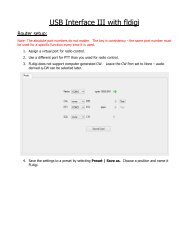
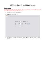
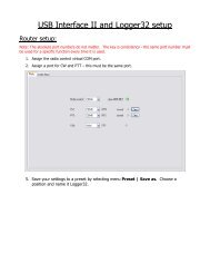
<strong>microHAM</strong> © 2010 All rights reservedConfiguring <strong>microHAM</strong> USB Device RouterThe <strong>microHAM</strong> USB Device Router (Router) program provides a Windows compatible configuration tool for<strong>microHAM</strong> USB Devices and software interface to other Windows applications (loggers, digital modesoftware, etc.). The software interface is provided as Virtual Serial Ports.To configure and use <strong>DIGI</strong> <strong>KEYER</strong> <strong>II</strong> with Windows compatible application programs it is necessary to haveinstalled the USB driver, started the Router, and applied power to <strong>DIGI</strong> <strong>KEYER</strong> <strong>II</strong> by turning on the attachedradio or external power supply. Router is then configured to match the requirements of the application(logger or digital mode) software.<strong>DIGI</strong> <strong>KEYER</strong> <strong>II</strong> StatusWhen the USB driver is installed correctly and DK <strong>II</strong> is poweredfrom a radio or external 12V DC supply Router will show a devicetab with a GREEN check beside the device name.When Router shows a YELLOW “X” instead of a green , itmeans the USB driver is correctly installed but DK <strong>II</strong> is notreceiving power from the radio or external supply.When Router shows a RED “X” instead of a green , it means thedevice is disconnected and Router does not see the USB part ofDK <strong>II</strong>.This happens when the USB cable is unplugged or the USB driver is not correctly installed.Initial SetupRouter must be used to configure DK <strong>II</strong> for proper operation. The device configuration tabs are used tosetup each part of the DK <strong>II</strong> – virtual ports for communicating with the application (Ports), audio levels,PTT, WinKeyer, keyboard operation, stored CW/FSK messages and System configuration.11
<strong>microHAM</strong> © 2010 All rights reservedCreating and Using Virtual Serial Ports<strong>microHAM</strong> Router provides a set of virtual serial ports which allow Windows applications (loggers and digitalsoftware) to work with DK <strong>II</strong> just as they would work with "real" (hardware) serial ports.In order to use these virtual Ports, you must first create the ports and then assign a function (radio control,PTT, CW, FSK, etc.) to each virtual port.DO NOT define a port that is already in use (for example, COM1 or COM2 which are hardware ports onmany motherboards) or a virtual port used by another USB device. Even though Router will not allow usinga COM port number which is already present in the system (like hardware COM ports or internal modems),sometimes these ports are hidden. If a device which also uses virtual serial ports (external USB devices,bluetooth devices, mobile phones, PDA etc ...) is not connected to the computer when creating virtual portsin Router, the ports can overlap and will not work properly when you connect such device.IMPORTANT WARNING: Before you start creating virtual COM ports, attach all external devices you usewith the computer and allow them to connect to the system. Restart Router and then create the virtual COMports.Virtual ports are created from the Virtual Port menu.Create - Creates virtual COM ports. It is possible toselect more than one port at a time by holding theCtrl key on keyboard and clicking on COM portnumbers. Creating virtual ports may take a long time(several tens of seconds), be patient.Delete - Deletes any single virtual port.Delete All - Deletes all previously created virtual ports.Do not delete a virtual port until all applications using that port have been closed.TIP: It is possible to select multiple ports at one time byholding Control key on keyboard and clicking on the COMport numbers.TIP: If you have uninstalled another device which usedvirtual ports and Router does not offer the released COMport number, you will need to reset the virtual port bus. Youcan do this by deleting all the virtual ports at once. Select"Virtual Port | Delete All" and create the ports again. Anymissing port number should appear.TIP: Do not create more virtual ports than your applicationsrequire. Extra ports only tie up system resources andmake Router load more slowly.12
<strong>microHAM</strong> © 2010 All rights reserved5 - <strong>microHAM</strong> USB DEVICE ROUTERROUTER MENUDefault Router Settings: used to completely reset Router to factory (default) settings."Default" removes all device tabs and deletes all stored configuration data, including all user presets.from the Windows Registry.TIP: DK <strong>II</strong> can be reset to the factory configuration by selecting Default Router Settings followed byDevice | Store as Power-up Settings to save the defaults to the keyer's memory.Restore Router Settings: used to restore settings from a urs file created by the backup command.A urs file can be used only with the device for which it was generated (the file contains the unit serialnumber) on a computer with same port assignments.WARNING: Restoring a backup replaces all current Router settings including presets, use it carefully!Backup Router Settings: used to create backup urs file.This file contains Router settings (including Presets) for all devices defined in Router.Options | General- Load Router on Start-up: when checked, Router will start automatically each time the computer isstarted or rebooted.- Start Router Minimized: when checked, Router will started minimizedOptions | Band Map: - Does not apply to <strong>DIGI</strong> <strong>KEYER</strong> <strong>II</strong> -Customizable band edge boundaries used to drive the band data output. BCD codes can becustomized for driving antenna switches or bandpass filter control.Options | Digital Band Map: - Does not apply to <strong>DIGI</strong> <strong>KEYER</strong> <strong>II</strong> -Customizable band boundaries for the digital mode operation. These settings are used for the (optional)automatic selection of audio switching and PTT mode based on operating frequency. Careful selectionof the "Digital band" is necessary for transceivers which do not have a special mode for AFSK operationor do not report the mode in the computer command set. This primarily effects Kenwood and TenTectransceivers although it applies to some older Icom and Yaesu radios.Options | Audio Devices:- Don't use audio devices: when checked, Router does not use audio devices and the settings on theAudio Mixer and DVK tabs have no effect.- Manually assign audio devices: when checked, Router will allow the user to select audio devices(sound card) in the appropriate fields at Audio Mixer tab and will actively control the audio devices- Automatically assign <strong>microHAM</strong> audio devices: when checked, Router will automatically assign properaudio device of the same name if multiple <strong>microHAM</strong> interfaces of the same kind are connected to theone computer.Options | DVK: - DVK is not supported by <strong>DIGI</strong> <strong>KEYER</strong> <strong>II</strong> -- Voice message time limit: maximum time for each voice message up to 120 seconds.- Sample rate: sampling frequency used during recording and playback of voice messages.- Sample size: sampling size used during recording of voice messages. Sampling size primarily effectsaudio quality of the messages. 16bit samples provide higher quality than 8bit.Options | USB:- Noise immunity: selects how many times an undelivered USB packet will be repeated before the USBdevice is disconnected from the operating system.- Response time: selects how long the USB chip in a device will wait for additional data before sendingdata to the operating system.13
<strong>microHAM</strong> © 2010 All rights reservedMinimize: Clicking this will minimize Router to thesystem tray at the bottom right corner of theWindows Taskbar (the "System NotificationArea").TIP: When Router is minimized you can restore it by double-clicking on the Router tray icon. You canalso restore Router by double-clicking on the Router icon on the desktop or restarting Router from thePrograms menu.Exit: Clicking on this item will terminate Router.NOTE: when Router is terminated, application software will be unable to communicate with<strong>DIGI</strong> <strong>KEYER</strong> <strong>II</strong> and the radio.PRESET MENUThe requirements of each program are different and each one may handle radio control, CW and PTT in itsown way. In some cases what works for one application may not work properly with another. To getmaximum performance from CW Keyer, you may wish to customize the settings for each application.For easy switching among applications, Router supports up to 12user definable Presets. Different configurations can be stored inthese presets and recalled almost instantly simply by clicking on thepreset button.Each preset contains the settings for all devices connected to, andcontrolled by, Router. For example, if Router controls amicro<strong>KEYER</strong>, a <strong>DIGI</strong> <strong>KEYER</strong> <strong>II</strong> and a USB Interface, each presetremembers the settings for all devices including the assignment ofCOM ports and the contents of all sub-tabs except the FSK/CWMessages and DVK tabs.NOTE: Presets do not appear until they have been saved by theuser using Preset | Save as. Example configurations forseveral popular loggin and digital programs are availble inRouter's Help menu. Use “Help | Download Documents“ ifthe setup guides are not available or are incomplete.There are three ways to apply a preset once it is created:1. Click on Preset and select the desired preset from the pulldownmenu.2. Click on a preset button. To have buttons visible in Router, Preset | Show Buttons must bechecked. When the settings from a preset are applied, a green light located in the preset button islit. This green light is on ONLY when all settings in Router are same as those stored in the preset.14
<strong>microHAM</strong> © 2010 All rights reserved3. By right clicking on the system tray icon when the Router is minimized.The presets and the current router configuration are stored to the registry whenRouter is closed and recalled when Router is loaded.Save as - Saves the current Router settings to a preset for future use.Rename - Allows renaming of an existing preset.Delete - Delete chosen preset.Show buttons - When checked, Router shows the preset buttons.DEVICE MENURouter can control several devices. This allows configuring the settings for all connected devices at onetime by using the Presets.Each device has its own tab (page) in the main Routernotebook. The content of a device tab depends ondevice type. Adding a device is automatic the firsttime Router detects a supported device (USB driver).Once detected, a device remains in Router even though device is disconnected. Each device is identifiedby product identification number and a unique serial string.Rename – Creates a custom device name. This is useful iftwo or more devices are connected to the Router. Forexample CW <strong>KEYER</strong>, micro Keyer and USB Interface <strong>II</strong> canbe renamed to more identifiable names as shown here..Delete - Removes a device from the Router. Onlydisconnected devices (those with a RED “X” on the devicetab) can be removed. To disconnect a device from Router,unplug the USB cable from the computer or device.Save Template - will save the current Router settings to template file.When clicked, Router will open a standard File Save dialog window – the default location isC:\Documents and Settings\All Users\Application Data\<strong>microHAM</strong>\cfg. If a hypertext (html) or plaintext (txt) documentation file of the same name as the template is present in the same directory, it willbe associated with the template.Load Template – will automatically configure Router from a template (*.tpl file).When clicked, Router will open a standard File dialog – the default location is: C:\Documents andSettings\All Users\Application Data\<strong>microHAM</strong>\cfg - and the desired template can be chosen. WhenRouter loads a template, it looks for an html or txt file with the same name as the template in thesame directory. If such file is found, it is displayed.TIP: Templates are a powerful tool for quickly configuring Router to work with a particularapplication. Template files are interchangeable between computers and are well suited for cloningsetups when using the same application in multi-computer stations or for sharing custom setupsbetween users.15
<strong>microHAM</strong> © 2010 All rights reservedUpload Firmware: <strong>microHAM</strong> will occasionally release updates to the firmware in <strong>DIGI</strong> <strong>KEYER</strong> <strong>II</strong>. Theupdate may support news feature in Router or improve application compatibility. The recent publicversion of the firmware is always available from www.<strong>microHAM</strong>.com/downloads.html.To update firmware, download the firmware file to your computer, then click on Device | UploadFirmware. A Windows file dialog will open; navigate to the directory into which you downloaded thefirmware file and select the file.TIP: When you upgrade Router, the upgrade will include the latest firmware file. The new firmwarewill be automatically uploaded to <strong>DIGI</strong> <strong>KEYER</strong> <strong>II</strong> when the new version of Router connects for thefirst time, you have just to allow the upgrade when prompted.VIRTUAL PORT MENUIt is necessary to create several virtual serial ports (COM ports) in order for a Windows application (logging,control or digital mode program) to access <strong>microHAM</strong> devices.Create - Creates virtual COM ports. It is possibleto select several ports at one time by holding theCtrl key on the keyboard and clicking on COM portnumbers. Creating a virtual port may take a while,be patient.Delete - Deletes any single virtual port.Delete All - Deletes all previously created virtualports and resets Virtual Serial Port bus.Do not delete a virtual port unless all applicationsusing that port have been closed.Virtual Serial Ports can be reviewed in DeviceManager, under the ELTIMA folder.NOTE: Properly working ports should not displayan exclamation mark (!).16
<strong>microHAM</strong> © 2010 All rights reservedHELP MENUManuals: Link to <strong>microHAM</strong> manuals located on your system.Setup Guides: Link to software configuration guides for many common applications.Cable Schematics: Link to cable diagrams.Download Documents: Downloads <strong>microHAM</strong> documentation including updated manuals and setupguides. You may specify the products for which you want documentation.NOTE: Download Documents requires an Internet connection.<strong>microHAM</strong> Home Page: Link to www.<strong>microHAM</strong>.com<strong>microHAM</strong> Downloads Page: Link to www.microham.com/contents/en-us/d29.htmlShow Tooltips: When checked, small, single line help is displayed below the mouse cursor.Update Router: Download and install the most recent version of Router.About: Shows the Router's internal version numberChange logs: Shows the Router and firmware changes.DEVICE CONFIGURATION TABSThere are nine (9) tabs for configuring <strong>DIGI</strong> <strong>KEYER</strong> <strong>II</strong>. Each tab controls a part of the device functions. Anychange is applied immediately to <strong>DIGI</strong> <strong>KEYER</strong> <strong>II</strong>. Changes in Messages are NOT applied automatically. Tostore them use buttons Store or Store All.Ports - used to assign virtual ports to the <strong>DIGI</strong> <strong>KEYER</strong> <strong>II</strong> for use by applications.Audio - used to configure on-off keying decoders (Q-CW/P-FSK) and CW side tone.Audio Mixer – duplicates the Windows Mixer for DK <strong>II</strong> in Windows XP and 2000 only.PTT – used to configure PTT outputs, timing and sequencer.CW / WinKey – controls WinKey settings.CW & FSK Messages – used to store and edit CW or FSK messages.Keyboard - used to configure the optional PS/2 keyboard or Keypad.System Settings – used to configure the optional Auxiliary CI-V output.17
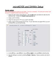
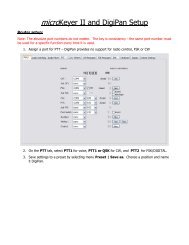
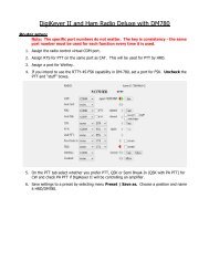
<strong>microHAM</strong> © 2010 All rights reservedPorts TabOnce the virtual ports have been created they must be associated with a specific device channel (e.g.,Control, CW, PTT, etc.). These assignments should correspond to settings of the application software andmust be configured first in Router then in the application (e.g., logging program, MMTTY, MixW, etc.).Proper configuration of the port assignments in this tab is critical for integration with logging anddigital mode softwre. Read the following information carefully.<strong>DIGI</strong> <strong>KEYER</strong> <strong>II</strong> has eleven functions with indication of the state and settings applied by the host application●●●●●●●●●●●CAT (uses RxD and TxD)2 nd CAT (virtual “fork” for the main CAT channel)FSK (uses TxD and optionally RTS/DTR for PTT)2 nd FSK (uses TxD and optionally RTS/DTR for PTT)CW (uses DTR or RTS)PTT (uses DTR or RTS)2 nd PTT (uses DTR or RTS)Foot Switch (uses CTS, DCD, DSR or RING)Squelch (uses CTS, DCD, DSR or RING)WinKey (uses RxD and TxD)Control (uses RxD and TxD)General note: Do not assign virtual ports to those functions which are not used by the application. It isunnecessary and only consumes resources.18
<strong>microHAM</strong> © 2010 All rights reservedCAT PORT & 2 nd CAT PORTThe CAT channel is used by application software to control transceiver frequency, mode, T/R switching andmany other parameters using a serial (CAT) protocol. Most modern radios implement some form of CAT butalmost every radio implementation is different. The functions controlled by the computer depend on theparticular application and radio.NOTE: The port number assigned in Router MUST match the port number assigned in the hostapplication. First configure the virtual COM ports in Router then configure the application.When a COM port is assigned in the Router but notin the application (or the application is not running)Router will indicate the channel is closed.When an application opens the COM port assigned for control (usually at start-up), Router shows thechannel as open and displays baud rate, data bits, parity and number of stop bits used by the application.For example, 4800 8N2 means: 4800 baud, 8 bits data length, parity = none, and two stop bits.Data flowing through the CAT channel is indicated by two arrows. A green arrow indicates data flow from theapplication to the radio and a red arrow indicates data flow from the radio to the application.TIP: If the application provides for PTT (T/R) keying by radio control (CAT) turn this function OFF.PTT by CAT is not reliable because RFI can prevent the radio from switching back to receive. Thereis a dedicated T/R switching channel for this purpose called PTT.NOTE: If your radio does not support handshake (most do not). Configure DTR and RTS settingsin your application program (logger) for Always On or Always Off. Do not select “Handshake.”For Router to determine the operating frequencyand mode, it must know what radio (CAT protocol)being used. To select the radio, click the Setbutton, choose your radio in the Radio combo box,select communication speed in the Baud rate box,and set the CI-V address for Icom and someTenTec radios.TIP: Disable the Autobaud function in any Icom Radio used with Router. Configure the radio,Router, and your application software to operate at 9600 or 19200 baud.Disable router queries – When this box checked, Router will not poll the radio for frequency and modewhen that information is not available from the communication between the application and radio.NOTE: "Disable router queries" disables Router polling only when the port has been openedby an application program. When the virtual port is closed, Router always polls the radio tosupport the automatic switching functions of <strong>DIGI</strong> <strong>KEYER</strong> <strong>II</strong>. If it is necessary to disable allpolling, select one of the "none" options in the Radio box.WARNING: DO NOT select "Disable Router queries" unless you have a specific reason to do so. Routeronly polls for information that is not requested by the logger and does not interfere with logger polling.Disabling Router queries may result in incorrect frequency and/or mode decoding and can have a seriousimpact on overall operation.19
<strong>microHAM</strong> © 2010 All rights reservedPW1 on radio bus – When this box checked, Router periodically generates an Icom "Transceive"broadcast to keep the PW1 synchronized.Tracking:NOTE: Check this box if you have an IC-PW1 or other Icom compatible accessory physicallyconnected in parallel with the transceiver. Do not check this box if the only connection is to thetransceiver and the PW1 or other other accessory is connected to the accessory CI-V port(described later).Tracking: This function allows an external receiver to track the transceiver attached to DK <strong>II</strong>.NOTE: The transceiver attached to DK<strong>II</strong> must be properly interfaced and CAT must befunctioning properly. Tracking does not work for “no radio” choices.Radio: Specifies SDR receiver model.Source QRG: Specifies whether the SDR will track the transceiver transmit or receive frequency.Port: Specifies COM port used to communicate with the SDR.Offset: Frequency offset between the receiver and transceiver. Default is 0Hz, resolution is 1Hz.NOTE: For specific receiver configurations, please refer to Appendix C..The bottom two-thirds of the Radiowindow is a serial communicationmonitor. The monitor uses colors andtags to indicate which device isresponsible for the data. Black queries(H1-TX or H2-TX) and gray radioresponses (H1-RX or H2-TX) are fromthe "host" application (e.g., logger), H1indicates the host application on themain CAT port, H2 is the hostapplication on the 2 nd CAT port. Greenpackets (R-TX and R-RX) arepolls/responses from/to Router and notrouted to the application.Router monitors the communicationwhen the host application performscontrol and polls the radio periodicallyfor any missing information (VFOfrequencies and mode). Becausesome applications do not poll the radioregularly or completely, Router mustbreak this communication to update its internal state. In order to avoid confusing the application whenRouter polls the radio, data from the application is buffered and sent to the radio after Router receives aresponse to its query. If Router does not receive response to a poll within the time allowed or does notunderstand the response, it displays "oldest query discarded" but forwards all data to the virtual serial portto avoid confusing the application (logger).Since USB transmits data in frames with a delay between frames, Router indicates frame boundaries withthree dots (...). When a packet ends with three dots it means that the data continues in the next frame.20
<strong>microHAM</strong> © 2010 All rights reserved2 nd CAT PORTBeginning with version 7.0, Router provides unique control capability: the 2 nd CAT Port is an intelligent datafork (software 'Y' connector) that allows a second application to share control of the radio. Router monitorswhen data is sent from each application and routes the radio's responses to the correct virtual port.IMPORTANT: Both applications must use same communication parameters (baud rate, data length, parityand number of stop bits) for proper operation!Neither CAT port has priority. Polls/commands from the application are processed alternately. In order toavoid collisions and confusion due to unexpected data, responses from the radio are returned only to theapplication that generated the command. Unsolicited data such as automatic frequency/mode updates(Icom "transceive" packets or "Auto-information" data from Kenwood, Elecraft and recent Yaesutransceivers) is forwarded to both CAT ports.Due to physical limitation of data channel throughput and the controller capabilities in various transceivers,there are several important rules which must be observed.●●●Combined data from both applications must not exceed maximum throughput of the radio controlport and transceiver controller. In other words, the polling rate from one application may need to bedecreased to provide data space for the second application and vice versa.Applications must be tolerant of delayed responses from the radio. Each application must wait forthe radio to respond when the another application is communicating with the radio.Due to protocol deficiencies in handling VFO split commands with many transceivers (particularlyIcom), split mode must be initiated and ended by only one application and manual split control(from the front panel of the radio) should not be used.NOTE: Despite extensive testing using various combinations of applications for the CAT and 2 ndCAT ports, <strong>microHAM</strong> cannot guarantee proper operation with every potential combination ofapplications.FSK & 2 nd FSK PORTSThe FSK channel is used by the application program to send the FSK keying signal. FSK is used primarilyfor RTTY. It is very important to understand the difference between FSK and AFSK.FSK is a digital (On/Off) signal from the computer serial port (or an external modem). This signal is used inthe transceiver to generate a frequency shift. FSK must be supported by the transceiver (this mode iscommonly labeled RTTY or FSK).AFSK is a analog (audio) signal generated by the computer sound card (or external modem) used in thetransceiver modulation circuits for operating digital modes as RTTY, PSK31, AMTOR etc. Computer soundcard generated AFSK or PSK does not require special transceiver support and can be used in the LSB,USB or FM mode of the transceiver. Some radios have dedicated modes for AFSK (generally labeled PKTor DATA) with special features.It is very important to properly adjust the audio drive level of an AFSK system so as to not overdrivethe first transmit audio amplifier stage in the transceiver and produce a wide, distorted signal, full ofintermodulation products. It is important to appreciate that distortion generated at this point due tooverdrive CANNOT be reduced or eliminated by the reduction of the microphone gain control – it isthe signal level that must be adjusted to be about the same as would be expected from amicrophone. The microphone gain control then becomes a form of transmit power control.21
<strong>microHAM</strong> © 2010 All rights reservedAn initial indication of proper audio drive level can be seen on the ALC meter of the radio. Providedthat there is NO audio processing in circuit and that the microphone gain control is in its normaloperating position, then, if the ALC does not show or just starts to indicate during transmission, thesignal is likely to be clean. It is also important is to turn off the microphone compressor, ANY transmitaudio equalizer, AND transmit DSP when AFSK is used. DO NOT use any form of digital modulation(sometimes called "Transmit DSP") with AFSK or PSK. Some transceivers bypass these circuitsautomatically when signal is routed to the rear audio jack instead of the microphone jack, but somedo not (for example, the TS-850).Edited by Geoff Anderson, G3NPATIP: If your transceiver supports FSK use it for RTTY whenever possible. In many transceiversRTTY (FSK) mode provides improved receiver filtering and is the only way to guarantee a cleanRTTY signal no matter how the microphone gain or compressor (processor) is set on yourtransceiver.When a COM port is assigned in Router but not in the application program (or the application is notrunning), Router will indicate the channel is closed.When an application opens the COM port,Router will indicate the channel is open anddisplay baud rate, number of data bits, parity andnumber of stop bits in use. For example, 455N1.5 means: 45 Baud, 5 data bits, no parity, 1.5 stop bits.The second FSK port is useful when operating split with radios that have two receivers (e.g., FT-1000, FT-2000, FT-9000, K3, Orion or IC-7800). The second instance of the RTTY program should specify "rightchannel" for its audio source and should be configured to use the 2 nd FSK port for its FSK output.Radios without a second receiver can use the 2 nd FSK port for a second RTTY program with a differentdecoding algorithm to provide diversity decoding and transmit from either program.TIP: If you see a baud rate other than 45.5 baud (e.g., 4800 or 9600), the application is NOTconfigured correctly for FSK RTTY operation.PTT: The virtual port used for FSK can also support PTT (required by MMTTY). When you use MMTTY,select the PTT box and RTS will used for PTT. Do not use the FSK port for any other function.Invert: Some transceivers lack the ability to set the sense of the FSK input. If you cannot set the propersense, check the invert box. This is normally necessary only with the TenTec Omni V, Omni VI andKenwood TS-940.Strict bps: Some programs rely on the the FSK port for proper PTT timing; they drop PTT (unkey) whenthe FSK port buffer is empty. With virtual ports, this may cause PTT to drop before the contents of amessage (macro) are complete. 'Strict bps' disables the virtual port buffering and transmits one characterat a time to the output. Due to the additional overhead, FSK output will be slightly slower but operation willbe more reliable.To test FSK operation from the computer to the radio, click on Test button with no port assigned or the portclosed. The Test button will generate "RY" two times.22
<strong>microHAM</strong> © 2010 All rights reservedCW PORTBy its very nature, USB is not well suited to transfer the real time events required for CW keying. Inaddition to the latency inherent in the USB protocol, delays due to CPU load, internal Windows messageprocessing (inter-process communication) and data flow from another peripherals sharing same the USBroot hub can result in transmitted characters that are garbled. To minimize these unwanted operatingsystem effects Router uses a specially developed oversampling and prediction algorithm to assure thesmoothest possible transfer of control signal events over USB. Using these techniques, CW keying in theRouter is, in most cases, usable up to 50 WPM if the application generates keying signals accurately anddoes not consume 100% of CPU time at the highest priority class.Router allows assigning a virtual serial port for software CW using DTR or RTS signals. The DTR* andRTS* are identical to DTR/RTS except that the output is inhibited for one second after the COM port isopened. RTS*/DTR* should only be used with programs that cause unwanted key-ups during startup.TIP: More applications use DTR for CW than RTS.When an application opens the COM port (usually atstart-up), Router will indicate the channel is open.The state of the CW channel is indicated by a red arrow. If port is opened, it does not mean that it isproperly configured. The red arrow will light in time with the transmitted CW when the port is properlyconfigured.To test CW operation, click on the Test button with no port assigned or the port closed.PTT & 2 nd PTT PORTSThe PTT channel is used for T/R switching of the transceiver, Power Amplifier and Low Noise Preamplifier(LNA). An internal T/R sequencer assures 100% protection against transmitting through the LNA or hotswitching of the PA when the PTT channel is used for T/R switching. More information about T/R switching,<strong>DIGI</strong> <strong>KEYER</strong> <strong>II</strong> PTT outputs and the sequencer is provided under the Keying Tab (page 21).Router allows assigning virtual serial ports for PTT using the DTR or RTS signals. DTR* and RTS* areidentical to DTR/RTS except that the output is inhibited for one second after the COM port is opened and .should only be used with programs that cause unwanted key-ups during startup.TIP: More applications use RTS for PTT than DTR.The state of the PTT channel is indicated by a green arrow. If the port is opened, it does not mean it isproperly configured. When the port is properlyconfigured, the arrow will light during the entiretransmission. To test PTT operation, click on theTest button with no port assigned or the port closed.The 2 nd PTT channel is identical to the primary PTT channel. 2 nd PTT provides a way for a secondapplication to key the radio if the primary application also controls PTT – for example, a logging programand CW reader/keyboard.TIP: Always use serial PTT instead of the radio command PTT or VOX. It is the only way to assureproper sequencing of a Power Amplifier, LNA, or receive antenna switch.To test PTT, click on the Test button with no port assigned or the port closed.23
<strong>microHAM</strong> © 2010 All rights reservedFOOT SWITCHEven though many applications do not monitor the status of the foot switch and do not have the ability toperform specific functions base on closing or releasing the foot switch, we have decided to implement thisfeature to the Router. Hopefully sometime soon applications will be able to detect the foot switch status anduse this this information for automating user functions like in the DOS based TRLog.Router allows assigning a virtual serial port to the foot switch channel and selecting one of four availableinput control lines (CTS, DCD, DSR or RING).NOTE: CTS is not available if the foot switch channel is shared with the radio control port. The state of thesignal on the virtual port can be inverted by checking inverted box.When a COM port is assigned for the foot switch but the application does not support foot switch status (orno application is running), Router reports the channel as closed.When an application opens the COM port (usuallyat start-up), Router reports channel as open.When the foot switch is pressed, this state is indicated by a red arrow.SQUELCH PORTEven though most applications do not monitor the squelch and do not have the ability to perform specificfunctions based on its status, we have decided to include this feature in Router. Perhaps somedayapplications will be able to detect the squelch and use this information for automated functions like audiorecording.Router allows assigning a virtual serial port to squelch as CTS, DSR, DCD or RING.When a COM port is assigned to the squelch channel in Router but not in the application (or no applicationis running), Router shows the channel as closed.When an application opens the COM port (usually at start-up), Router shows channel as open.When squelch is closed, this state is indicated by a red arrow.24
<strong>microHAM</strong> © 2010 All rights reservedWinKey PORTWinKey is a unique external CW processor developed by Steve Elliot, K1EL. This CW processor supportspaddle input like any other electronic keyer, offers many configuration options, and in addition convertsASC<strong>II</strong> data from the computer to Morse characters. This unique property assures perfectly timed CWoutput from the computer regardless of OS load. More detailed instruction for configuring WinKey is foundin the description of the CW/WinKey tab.When a COM port is assigned to WinKey in Router but not in the application program (or no application isrunning), Router reports the port closed.When an application opens WinKey, (usuallyat start-up), Router shows the port open anddisplays settings used to configure COM port.TIP: If you see settings other than 1200 8N#, the application is not configured correctly for WinKey.If the data rate is incorrect, Router will transfer data to to Winkey at 1200 baud. However, reliableoperation is not guaranteed.Data flow is indicated by two arrows. The green arrow indicates data flow from the application to WinKeyand the red arrow indicates data flow from WinKey to the host application.Test: Sends "Test" via Winkey when the channel unassigned or closed.Mon: “WinKey Monitor” allows capturing communications between Router or the application and WinKey.Controls for the monitor include Start, Stop, Clear and Save.WinKey Monitor should not be used under normal conditions. However, if there are problems withWinKey and a logger, it may be useful to Start a capture and close the window. When a problem isnoticed, the window can be opened and the WK communications log Saved for analysis.WinKey Monitor is circular – only the last 20 kilobytes or so will be saved in order to prevent creatingvery large files.WK Monitor will display a description of each command from Router or the application and“decoded” response from WinKey. “ If a line ends in three dots (...) it means that the command orresponse has been broken across two USB packets.CONTROL PORTThe Control Port allows an application program (logger) that implements the <strong>microHAM</strong> Control Protocol tomake use of <strong>DIGI</strong><strong>KEYER</strong> <strong>II</strong>'s CW and FSK message memoriesWhen an application opens the control port, Routerreports port as open and displays settings used toconfigure COM port.Data flowing through the channel are indicated by two arrows. The green arrow indicates data flow from theapplication and a red arrow indicates data to the host application.Mon: Opens a “Control Protocol Monitor” window to capture <strong>microHAM</strong> Protocol communications betweena logger and Router. Controls for the monitor include Start, Stop, Clear and Save.25
<strong>microHAM</strong> © 2010 All rights reservedThe Control Protocol Monitor should not be needed under normal conditions. However, if there areproblems with a particular logger, it may be useful to Start a capture and close the window. When aproblem is noticed, the window can be opened and the Control protocol log Saved for analysis.The monitor log is circular – only the last 20 kilobytes or so will be saved in order to prevent creatingvery large files.AUDIO TABIn addition to providing for basic “Line Out” audio for digital mode operations, <strong>DIGI</strong> <strong>KEYER</strong> <strong>II</strong> has expandedcapabilities to support the <strong>microHAM</strong> micro2R two radio controller and the special on/off keying modes(p-FSK and q-CW) of fldigi by W1HKJ. These enhanced capabilities are controlled from the Audio tab.Use Q-CW: connects the right channel tone decoder to the CW output toallow audio tones to be used for “hard keyed” CW. This permitsCW decoding software that only generates audio output to beused with the CW function in most rigs.Use P-FSK: connects the right channel tone decoder to the FSK output.This allows the on/off keyed tone generated by fldigi to be usedwith the normal “RTTY” (FSK) mode of most rigs. .Force LINE IN selection: (Windows XP Only) Disables the “u2R Mic” input (rear panel) when <strong>DIGI</strong><strong>KEYER</strong> <strong>II</strong> is not used with a <strong>microHAM</strong> micro2R.Sound Card: is only visible with Windows Vista or Windows 7. It displays the Mixer ID, Wave In IDand Wave Out ID for each input/output.Side Tone:<strong>DIGI</strong> <strong>KEYER</strong> <strong>II</strong> includes an internal piezeo speaker for sidetone. The sidetonefrequency is selectable from 338, 450, 675 and 1350 Hz. Sidetone canbe enabled for all CW output or only manual (paddle) input.26
<strong>microHAM</strong> © 2010 All rights reservedAUDIO MIXER TABNote: The Audio Mixer Tab is not present in Vista or Widows 7 due to operating system limitations.The sound card configuration depends on the capability of your application software. Some software candirectly control the sound mixer controls some can not. Router's Audio Mixer tab provides the ability tostore and recall level settings to the presets for each application (or operating configuration).Select <strong>microHAM</strong> CODEC to use the internal soundcard in <strong>DIGI</strong> <strong>KEYER</strong> <strong>II</strong>.Router displays separate controls for the left and right Wave, Line Out (Volume) and Line In channels.<strong>DIGI</strong> <strong>KEYER</strong> <strong>II</strong> uses the left channel for all audio output. The right channel is used by the P-FSK/Q-CWdetector.NOTE: Windows can reassign sound cards "on the fly" and Router may not always select the correct mixerif you have more than one soundcard in your system. To confirm that the proper mixer has beenassigned, click the Get ID button and confirm that <strong>microHAM</strong> CODEC is selected. If the correctsoundcard is not selecetd, restart Router.27
<strong>microHAM</strong> © 2010 All rights reservedTX VOICE/<strong>DIGI</strong>TAL (transmit levels)These controls adjusts the output (transmit) levels. If the channels are active, thegreen rectangle will be on. If not, click the TX Mixer button and unmute the masterVolume (Speaker) and Wave controls.There are two (or four) sliders, the WAVE slider and MASTER slider (the MasterVolume or Speaker control).As a starting point, set the MASTER level to about 80% and the WAVE level to about50%. Adjust WAVE for proper drive when using digital modes. Adjust the MASTERonly if necessary to keep the WAVE control from operating at one end of its range.NOTE: To enable P-FSK or Q-CW audio keying on the right channel, the rightchannel MASTER and WAVE sliders must be at 100%. Any value below 90%for the RIGHT sliders will not allow the detector to operate properly.Test Signal: causes <strong>DIGI</strong> <strong>KEYER</strong> <strong>II</strong> to output a 1500 Hz audio tone for setting thetransmit output level for AFSK digital modes.TX Mixer: this button opens the Windows Volume Control (Playback Mixer) for theselected sound card.Some tips from Geoff Anderson, G3NPA:TIP: If you have achieved the correct settings for the transmit levels (with audiocompression disabled), changing from a single tone to the PSK idle should make transmitpower drop by at least 50% as observed on an RMS or average reading meter. Thischange in power is correct. If you do NOT see a 50% (or more) change, you are probablyover driving the radio. Please note that some radios have inbuilt power meters which givea PEAK reading and therefore the change in level discussed above will not be observed.TIP: Don't fall into the trap of thinking that because the transmit signal looks good on thewaterfall that your actual signal is OK. All the waterfall is showing during transmit is the localaudio and NOT the transmitted signal.RX RECORDING/<strong>DIGI</strong>TAL (digital decode levels).VU meter: this "stacked LED" display shows the audio level into the analog todigital controller. Note, the display is active only if a sample rate isselected.<strong>DIGI</strong> <strong>KEYER</strong> <strong>II</strong> shows one slider for each input – Left for the Main RX and Rightfor the Sub RX. Keep the sliders at about 80% and use the RX Main and RXSub pots on the front panel for adjustment. When correctly adjusted, the inputsignal should never show RED.Sampling: sets the sample rate used for the RX level displays.Because of the of the way the Windows sound system handles multipleaccess to the sound card, always turn off the level displays (setSampling: off) when they are not in use.Rec/RX Mixer: this button opens the Windows Record (Input) Mixer for theselected sound card.Get ID: this button will retrieve the name and number of the sound card. Thename can be used to verify that the correct sound card has been selected. TheWave In ID can be used to configure software that identifies sound cards only by number.28
<strong>microHAM</strong> © 2010 All rights reservedPTT TAB<strong>DIGI</strong> <strong>KEYER</strong> <strong>II</strong> has three (3) PTT outputs: PTT, PA PTT and LNA PTT. PTT is brought out to the DB15 Radioconnector. PA PTT and LNA PTT are available on RCA connectors at the <strong>DIGI</strong> <strong>KEYER</strong> <strong>II</strong> rear panel.PTT is normally wired to the radio Accessory jack and isused to switch the radio into transmit.PA PTT is present at the <strong>DIGI</strong> <strong>KEYER</strong> <strong>II</strong> rear panel RCAjack and is designed for switching a poweramplifier. PA PTT is enabled by checking thePA PTT box.PA PTT will close before transceiver PTT by thetime selected for PTT Lead tail and will open atthe same time as the transceiver PTT.LNA PTT is present at the <strong>DIGI</strong> <strong>KEYER</strong> <strong>II</strong> rear panelRCA jack and is designed for switching(bypassing) a low noise preamplifier (LNA)during transmit. LNA PTT is enabled bychecking the LNA PTT box.LNA PTT will close before the transceiver PTTby the time selected for PTT Lead and and willopen after the transceiver PTT by the timeselected for LNA PTT Tail.PTT output generally folows the PTT inputs (PTT port, PTT In, Soundcard PTT and WinKey PTT).PTT behavior is configurable in CW Mode.CW options are: PTT (normal operation),QSK (no transceiver PTT, PA PTT has norelease delay), and Semi Break-in (notransceiver PTT, PA PTT includes releasedelay).PA PTT: Enables PA PTTLNA PTT: enables NA PTTSound card PTT: Enables automatic PTT when thesound card has been “opened” for output bythe operating system.PA PTT tail: delay between release of transceiverPTT and PA PTT.LNA PTT tail: delay between release of transceiver PTT and PA PTT.Invert: when checked, LNA PTT sense is reversed (closed in receive).PTT lead: delay between closing PA PTT/LNA PTT and Transceiver PTT/CW output.However,PTT tail: how long the transceiver PTT is remains closed following the last CW element. PTT tail can be a fixedlength from 10 to 2500 ms or proportional to the CW Speed.29
<strong>microHAM</strong> © 2010 All rights reservedFOOTSWITCH SEQUENCERAdditional functions can be associated with the footswitch (or hand mic PTT). <strong>DIGI</strong> <strong>KEYER</strong> <strong>II</strong> recognizeswhen the footswitch is closed (pressed) or open (released) and can manipulate CW, FSK, PTT and audiorouting when the footswtich is closed or opened.Mute serial CW - if checked, serial CW (DTR or RTS) from anapplication program will be muted while the footswitch ispressed. If Restore serial CW is checked, CW willresume when the footswitch is released (if it has notalready ended). If Restore serial CW is not checked,application generated CW will remain suppressed untilthe application releases PTT.Mute serial FSK - if checked, the FSK ports will be blockedwhile the footswitch is pressed. If Restore serial FSK ischecked, FSK will resume when the footswitch isreleased (if it has not already completed). If Restoreserial FSK is not checked, FSK will remain suppresseduntil the application releases PTT.Restore serial PTT and audio - if checked, application generated serial PTT will be restored and audiorouting will return to the “serial PTT” setting when the footswitch is released. If Restore serial PTTand audio is not checked, audio will only return after the application releases PTT.30
<strong>microHAM</strong> © 2010 All rights reservedCW / WinKey TABThis tab provides the configuration for the WinKey based, internal CW keyer. A complete WinKey manualcan be downloaded from: http://k1el.tripod.com/docfiles.html. Thanks to Steve Elliott, K1EL for this greatproduct.WinKey can be controlled by a logging program or operate in stand alone mode controlled by Router.Router controls the speed range, Paddle mode and other timing characteristics of WinKey. When anapplication opens WinKey, all buffer handling and speed changes are strictly under application control.When WinKey is closed, the basic operating parameters can be adjusted on this tab. Every change isapplied immediately.Paddle Mode● Iambic A (Curtis)● Iambic B (Accu-keyer)● Ultimatic (Single lever)● Bug Keyer(Vibroplex emulation)Priority – Ultimatic mode offersa choice if DIT or DAHpriority for dual leverpaddles. If no priority isselected, the keyer works ina "last paddle wins" mode.Paddle set point - controls when WinKey begins looking for a new paddle press after sensing the currentone. The default value is one dit time (50) and is adjustable in percent of a dit time.Disable paddle memory – When checked, DIT (or DAH) insertion is disabled.Swap paddles - Reverse paddle sense for left handed operation or improperly wired paddle.Auto space - Keyer generates automatic character space.CT space - Selects “contest” word space (six elements long instead of seven).Speed pot min/max - Min/Max value of the front panel speed knob (9) in range 5 to 99 WPM.Farnsworth speed – Sets the Farnsworth keying speed (10 to 99 WPM range, 0 disables this feature).DIT / DAH - DIT/DAH ratio from 1:2 to 1:4 in hundreds. Accepted numbers are from 200 to 400.Weighting - Weighting in percentage (from 10 to 90%).1 st extension - Extension of the first dit or dah in milliseconds (QSK only).Keying compensation - Extension of each dit and dah in milliseconds ( QSK only).31
<strong>microHAM</strong> © 2010 All rights reservedCW MESSAGES TABOn this tab you can define nine CW messages of up to 50 characters each which are stored in EEPROM.Each memory may have a programmable repeat delay and/or call another memory.Commands which may be included in a memory are:Merge: merge two characters without a letter space – [M]AS will sound AS .-...Cancel WPM: restore speed set by the Speed pot.Set WPM: force speed to the selected value regardless of position of speed knob.Set Key: close CW output for selected time in seconds.Set Wait: wait selected seconds during playback.Jump to:Delay:Test:Store:Store All:used for looping a message or calling another messagesets the delay in seconds before looping or calling another messageplays a message without storing itsaves one message to <strong>DIGI</strong> <strong>KEYER</strong> <strong>II</strong> memorysaves all messages to <strong>DIGI</strong> <strong>KEYER</strong> <strong>II</strong> memoryLoad from File: loads all messages from fileSave to File: saves all messages to fileMessages can also be saved and replayed using an external keyboard or numeric keypad attached to thePS/2 jack. See: External Keyboard.NOTE: Messages are not saved or loaded with Presets32
<strong>microHAM</strong> © 2010 All rights reservedFSK MESSAGES TAB<strong>DIGI</strong> <strong>KEYER</strong> <strong>II</strong> allows defining nine messages of up to 50 characters each which are stored in non-volatilememory. Each memory may repeat with a programmable delay (loop) or call another memory (chain).Commands which may be included in a memory are:CR & LF:Jump to:Delay:Store:Store All:Insert Carriage Return/Line Feedused for looping a message or calling another messagesets the delay in seconds before looping or calling another messagesaves one message to <strong>DIGI</strong> <strong>KEYER</strong> <strong>II</strong> memorysaves all messages to <strong>DIGI</strong> <strong>KEYER</strong> <strong>II</strong> memoryLoad from File: loads all messages from fileSave to File: saves all messages to fileMessages can also be saved and replayed also using an external keyboard attached to the Remote jack.33
<strong>microHAM</strong> © 2010 All rights reservedKEYBOARD TABThe Keyboard Tab controls the operation of a PS/2 keyboard or numeric keypad connected to the PS/2jack. It is also possible to define control functions for the numeric keypad. Custom controls are invoked bypressing and holding the asterisk key (*) with Numkey0-9.General:QWERTZ layout – configures the keyboard for a QWERTZ layout.FSK from keyboard:Diddle LETTERS: send the LETTERS character whenever there is nothingin the transmit buffer.UOS: shift back to LETTERS case whenever a space is enountered in thetransmit data.Type ahead: enables type ahead when using a PS/2 keyboard. Characters are transmittedafter a space (word mode) or when the buffer has reached its limit (16 characters).CW from keyboard:Type ahead: enables type ahead when using a PS/2 keyboard. Charactersare transmitted after a space (word mode). or when the buffer hasreached its limit (16 characters).Speed Step: set the amount by which the Up/Down or NUM +/- keys changethe CW speed.Auto numbering:Leading zero as T: sends leading zeros in contest report as T. For example001 will be send as TT1.Zero as T: sends all "zeros" in contest report as T. For example number 100will be send as 1TT.One as A: sends all "ones" in contest report as A. For example number 101will be send as A0A.Nine as N: sends all "nines" in contest report as N. For example number 199will be send as 1NN.Report 5NN: send 5NN before contest serial number.The PS2 and FH-2 sub-tabs allow assigning control functions to PS/2 and FH-2 style keypads.34
<strong>microHAM</strong> © 2010 All rights reservedSYSTEM SETTINGS TABSystem Power displays the input voltage at pin 1 of the Radio connector.CI-V port settings: The CI-V port will emulate an Icomtransceiver and “broadcast” the frequency data if Routercan determine it by polling the rig or reading polling datafrom the logging program. The transceive broadcast canbe used to control peripherals that use Icom protocol.There are five frequencies which can be broadcast: RX frequency, TX frequency, Operatingfrequency, VFO A frequency or VFO B frequency. In practice, operation of each setting depends onthe transceiver and its CAT protocol. All options may not work with some transceivers.Baud Rate: sets the baud rate for the CI-V broadcastAddress: sets the “from” CI-V address for the CI-V broadcast6 - SETTING AUDIO LEVELSThere are three pots on <strong>DIGI</strong> <strong>KEYER</strong> <strong>II</strong> for adjusting audio levels.The TX Pot adjusts the level of audio to the transmitter. The RX MAIN Pot provides adjustment of the audiofrom the radio (main receiver) to the sound card (computer) left channel. The RX SUB Pot providesadjustment of the audio from the radio (sub-receiver) or a second receiver to the sound card (computer)right channel.IMPORTANT: Many transceivers, including all Yaesu transceivers, MUST be switched to aspecial digital mode (DIG, PKT, DATA, USB-D/LSB-D etc.) to enable the rear panel line input!Setting audio levels in Windows 2000 and Windows XP:(for Vista or Windows 7, skip to the next section) .1. On the Audio Mixer and select <strong>microHAM</strong> CODEC in both the TX and RX boxes.2. Click on the "Get ID" button and confirm that the correct sound card is selected.3. Set the front panel TX Pot to the 12:00 position.4. Set the TX Master and Wave levels to 80.5. Switch your transceiver to AFSK mode (PKT, DIG or DATA for Yaesu, LSB-D or USB-D for current Icomtransceivers, RTTY or RTTY-R on K2 and USB or LSB for Kenwood, TenTec and older Icomtransceivers). Do not select RTTY or FSK; they do not use the audio input.6. Click the "Test Signal" button and adjust the TX WAVE slider for normal (rated) output on yourtransceiver while keeping the ALC meter as low as possible.35
<strong>microHAM</strong> © 2010 All rights reservedNOTE: For the Elecraft K3 and other transceivers that have a separate “line In” control, do notadjust the TX WAVE slider. Instead, adjust the Line In level until the ALC shows the correct level.7. Set the RX RECORDING/<strong>DIGI</strong>AL sliders to approximately 80% and adjust receive audio levels with theRX MAIN and RX SUB controls on the front panel of <strong>DIGI</strong> <strong>KEYER</strong> <strong>II</strong>.8. You may want to store these Router settings to the last preset. Click Preset | Save as, choose positionnumber 12, name it Default and store settings.TIP: When you start to create your own presets, always begin by selecting the "default" preset.This will configure the audio levels to the proper state before starting any customization.Setting audio levels in Vista and Windows 7:Because Vista and Windows 7 do not allow one application to set the overall (master) audio levels it isnecessary to set up the sound card levels using the Windows Sound Control Panel.1. On Router's Audio tab, click the "Sound Card" button.2. On the "Audio Devices" window, select "Headset Earphone (<strong>microHAM</strong> CODEC)" in the Mixer andWaveOut boxes.NOTE: You may need the WaveOut and WaveIn indexes of the sound card to configure someprograms. Make note of them or remember where you can find the "Sound Card ID" numbers.36
<strong>microHAM</strong> © 2010 All rights reserved3. Click the TX Mixer button. If the Mixer does not appear,open the Windows Sound Control Panel and select the"Playback" tab.4. Click the "Test Signal" button on the Audio Devices screenand verify that the VU Meter for connected sound cardreaches maximum. If not, turn off Test Signal, restartRouter and return to step 1. Turn off the Test Signal.5. Select the "Playback" tab in the Sound Control Panel● double click "Headset Earphone (<strong>microHAM</strong>CODEC)"●●click Levels tab and unmute Headset Earphoneclick Balance and set LEFT (1) to 80% and RIGHT(2) to 100%NOTE: to enable "p-FSK" or “q-CW” audio keying on theright channel, the Headset Earphone and right channel (2)level must be at 100%. The audio detector will not operate properly at any value below 90%.6. Switch your transceiver to AFSK mode (PKT, DIG or DATA for Yaesu, LSB-D or USB-D for currentIcom transceivers, RTTY or RTTY-R on K2 and USB or LSB for Kenwood, TenTec and older Icomtransceivers). Do not select RTTY or FSK; they do not use the audio input.IMPORTANT: Many transceivers, including all Yaesu transceivers, MUST be switched to specialdigital mode (DIG, PKT, DATA, USB-D/LSB-D etc.) to enable the rear panel line input!7. Click the "Test Signal" button and adjust the LEFT level for normal (rated) output on your transceiverwhile keeping the ALC meter as low as possible. Turn off the Test Signal.NOTE: For the Elecraft K3 and other transceivers that have a separate “line In” control, do notadjust the LEFT slider. Instead, adjust the transceiver Line In level (mic gain) until the ALC showsthe correct level.8. Select the "Recording" tab in the Sound Control Panel● double click on "Line (<strong>microHAM</strong> CODEC)"● click Levels tab and unmute Line● set level slider to 80% and click "OK"9. Adjust receive audio levels for your applications using the Rx Main and RX Sub controls.37
<strong>microHAM</strong> © 2010 All rights reserved7 - EXTERNAL KEYBOARD/KEYPADNOTE: The keyboard or keypad must be PS/2. A USB device with PS/2 adapter will not work properly.<strong>DIGI</strong> <strong>KEYER</strong> <strong>II</strong> includes the ability to generate CW/FSK or record and play CW/FSK messages using akeyboard or numeric keypad connected to the PS/2 jack. A numeric key pad will allow recording/playingCW messages, control CW speed (WPM) or play a serial number message. “Live” CW/FSK (RTTY) orstoring FSK messages requires a full keyboard.Switching modes:The keyboard or keypad mode will follow the mode of the transceiver. If the radio is not computercontrollable or its control protocol is not supported, the keyboard or keypad can be used to switch Router'smode if the “radio” selection is “no radio (mode selected manually).”Playing messages:STATUS INDICATIONNUM CAPS SCROLL play/rec modeOFF x x playbackON x x recordingx OFF OFF CWx OFF ON <strong>DIGI</strong>TALx ON OFF FSKA message is started by pressing F1-F9 on the keyboard or 1-9 on the number pad. A message can beaborted with the ESC key or the zero key on the number pad. Messages may be made to repeat (loop) bypressing DEL (period) on the number pad while the message is playing. The default (minimum) wait timeafter ending a message before starting again is one second. The pause time may be set from 1 to 9seconds by entering the desired delay immediately after pressing DEL. For example, 1 5 will startmessage number 1 and cause it to repeat with five a second delay. Pressing zero (0) will terminate amessage loop.Recording messages:Recording is started (and stopped) by pressing NUM LOCK. To start recording, press NUM LOCK followedby the number of the message to be recorded. To abort a message without saving, press zero on thenumber pad or Escape. To end recording and save the message press NUM LOCK.In CW, DK <strong>II</strong> stores characters as they are echoed from the internal WinKey: only those characters actuallytransmitted are stored. However, CW messages may be recorded from either paddles or the keyboard.The gap “|” and other WinKey commands cannot be entered from the keyboard but may be used inmessages loaded from Router’s CW/FSK Messages tab.In FSK, all characters entered from the keyboard are stored.38
<strong>microHAM</strong> © 2010 All rights reservedstd. keyNUM LOCKNUM *ESC NUM 0Numeric KeypadF1-F9 NUM 1 – NUM 9ALTPG UPUPPG DNDNHOMEENTERNUM DELNUM /NUM +NUM -NUM ENTERstart/stop recording of message (recording mode is indicatedby NUM LED)Tune (can be canceled by keys NUM 0 or ESC, or by thepaddle)playback: stop transmitting (message or any characters inbuffer)recording: abort recording without storing the messageplayback: start message playbackrecording: set message numberplayback: periodically repeat last message (default interval is1 second, it can be changed by pressing the number onnumber pad)recording: no functionSwitch between "speed control mode" and "serial numbermode" (serial number mode is indicated by SCROLL LED, ifpresent)When held allows setting the serial numberCWmodeWPM control Increase CW speed (step defined by configuration) S/N mode Increment number by one without transmitting WPM control Decrease CW speed (step defined by configuration) S/N mode Decrement number by one WPM control Reset CW speed to pot (knob) value S/N modeTransmit number with optional report and increase number byone (format defined by configuration)ENTER transmit CR and LF characters F10 Toggle PTT – alternative to foot switch CAPS LOCKSPACE|0-9 a–z "#$%&'()*+,-./:;?@\0-9 A–Z !"$&='(),-./:;?Switch between CW mode and FSK mode(FSK mode is indicated by CAPS LED)transmit space (if "type ahead" mode is active all bufferedcharacters are transmitted before this space)transmit gap (one-half dit delay time), this character cannotbe recorded to a message from keyboard – it may only beentered from Routertransmit character, if "CW type ahead" mode is activecharacter is pushed to type ahead buffer to be transmittedafter next space. Note: some special characters are mappedto standard prosigns (see WinKey manual)transmit character, if "FSK type ahead" mode is activecharacter is pushed to type ahead buffer to be transmittedafter next spaceFSKmode39
<strong>microHAM</strong> © 2010 All rights reserved8 - System Considerations<strong>DIGI</strong> <strong>KEYER</strong> <strong>II</strong> can be used with a wide variety of software. The capabilities of those packages will havelarge influence on the level of computing power needed to utilize DK <strong>II</strong>.When used with Windows based contest logging applications like N1MM Logger, Win-Test, and WriteLog orWindows based general logging applications like DXLab Suite, DX4WIN, Logger 32 and others, the<strong>microHAM</strong> control and interface application “<strong>microHAM</strong> Router” must run along side the applicationprogram. Since both the logging programs and <strong>microHAM</strong> Router are real-time applications, systemperformance will be dependent on both CPU speed and the amount of available RAM.While <strong>microHAM</strong> Router will run on slower computers, the minimum tested system is a 1.6 GHz Pentium IV,Windows XP, 512 MB RAM, CD-ROM, and USB 1.1 port. Whether Router can run as designed on slowermachines with less memory and leave enough resources for application programs has not beendetermined. <strong>microHAM</strong> Router is not supported on any 16 bit version of Windows (95, 98, ME, SE).In order to provide sufficient performance for simultaneous operation of <strong>microHAM</strong> Router, a loggingapplication, Internet connectivity and other accessory programs, the recommended system is a 2 GHz PCcompatible computer with Windows XP Home or higher, 1 GB RAM, CD-ROM, root USB 2.0 port, atransceiver with supported control protocol and logger, control, or digital mode software.<strong>DIGI</strong> <strong>KEYER</strong> <strong>II</strong> is also compatible with Apple Macintosh systems running OS 10.4 or later. It is directlysupported by MacLoggerDX (www.dogparksoftware.com/MacLoggerDX.html) by Don Agro, VE3VRW aswell as µH Router and cocoaModem (http://homepage.mac.com/chen/w7ay/Site/Applications/index.html) byKok Chen, W7AY.9 - PACKAGE CONTENTSThe product includes <strong>DIGI</strong> <strong>KEYER</strong> <strong>II</strong>, USB cable, RCA to RCA cable, and CD-ROM containing the<strong>microHAM</strong> USB Device Router program and documentation. If the shipment is incomplete, please contactus at the following address:E-mail:support@microham.comfax :+421 2 4594 5100by Post:<strong>microHAM</strong> s.r.o.Nadrazna 3690028 Ivanka pri DunajiSLOVAKIA40
<strong>microHAM</strong> © 2010 All rights reserved10 - WARRANTY<strong>microHAM</strong> warrants this product for three (3) years. The product must not be modified in any way or thewarranty is voided. Cables are warranted against defects in materials and workmanship for a period of 60days.What is covered: During the warranty, <strong>microHAM</strong>, s.r.o., will repair or replace defective product at their solediscretion. You must send the unit postpaid with a copy of the original invoice to the distributor from whomyou purchased the product. <strong>microHAM</strong> will pay return shipping.What is not covered: This Limited Warranty does not cover (1) correction of installation or software errorsin the user's computer(s), (2) damage caused by misuse, negligence, user modifications or failure to followthe user manual, (3) connection to improper or excessive voltage or voltage surges, (4) the incorrectinstallation of any cables connected to the device by the user or (5) weather related storm, lightning orelectrostatic discharge damage.<strong>microHAM</strong> USB Device Router (the software) is provided “as is” without guarantee of compatibility withany specific operating system, computer, peripheral or accessory.<strong>microHAM</strong> assumes no liability or responsibility for damage to other devices or injuries to persons as aconsequence of using our products.If the terms of the above warranty are not acceptable, return the unit, all associated documents andaccessories in the original unopened package, prepaid, to <strong>microHAM</strong> or to your supplier for refund lessshipping and a restocking fee.41
<strong>microHAM</strong> © 2010 All rights reserved11 - SPECIFICATIONS<strong>DIGI</strong> <strong>KEYER</strong> <strong>II</strong> is a multi-mode interface between computer and transceiver. It has been optimized foramateur digital modes and includes a high performance USB sound processor.<strong>DIGI</strong> <strong>KEYER</strong> <strong>II</strong> is connected to the computer using a single A-B USB cable which is included.The transceiver and <strong>DIGI</strong> <strong>KEYER</strong> <strong>II</strong> are connected by single radio cable terminated on one side by aDB15M and on the other side by the appropriate plugs for the specific transceiver. The cable carries powerfor DK <strong>II</strong>, audio, CAT control and keying. The appropriate transceiver interface cable is specified when <strong>DIGI</strong><strong>KEYER</strong> <strong>II</strong> is purchased.If a Windows PC running the "<strong>microHAM</strong> USB Device Router" program is connected, <strong>DIGI</strong> <strong>KEYER</strong> <strong>II</strong> worksas a computer interface and sound card. It transfers all control signals generated by the applicationprogram between the computer and transceiver. Software compatibility is provided by using virtual serialports. Router monitors these virtual ports and transfers any data or commands by USB to the microcontroller in <strong>DIGI</strong> <strong>KEYER</strong> <strong>II</strong>.DK <strong>II</strong> processes this data and sends it to the physical ports of transceiver as CAT, CW, and PTT functions.The USB sound processor in <strong>DIGI</strong> <strong>KEYER</strong> <strong>II</strong> independently provides analog to digital conversion of audiofrom the transceiver and transfers it via USB to the computer where the operating system processes thatdata as a “sound card.” The USB sound processor also receives digital audio from any applications runningon computer and converts that data into audio signals to modulate the transceiver.<strong>microHAM</strong> Device Router is not required in order to enable the USB sound functions. The USB soundprocessor is supported directly by Windows, Mac OS X, and LINUX. It may be used by any applicationcompatible with those operating systems.Hardware SpecificationsUSB: USB 2.0 Full speed , USB 1.1 compatiblePower consumption: USB – less than 100mA; Transceiver – less than 200mA at 13.8V (max. 16V)Radio Port: RxD, TxD – max. 57,600 BaudLevels: Jumpers selectable TTL, inverted TTL, open collector bus, RS232CI-V Port: open collector bus – max. 9600 baudCW: open collector, max 30V/400mAFSK: open collector, max 30V/400mA– supports 5/6/7 bit data, 1/1.5/2 stop bits, up to 300 baudPTT: open collector, max 30V/400mAPA PTT/LNA PTT: selectable by internal jumper– open collector, max. 45V @ 0.8A– relay contact, max. 48V AC/DC @ 1AFoot Switch: active when closed to ground, max load: 1 mA at 5VPTT IN: active when closed to ground, max load: 1 mA at 5VAudio Out: 16bit, max 48000sps, Zout: 600 Ohm, 1.5V p-p @max. settings, Left channel, AC coupledAudio In: 16bit, max. 48000sps, Zin: 50K Ohm, max 4V p-p, dual channel (Stereo),60mV p-p for full scale @max. settings, AC coupledDimensions: W 165mm (6 1/2") x H 44mm (1 3/4") x D 110 mm (4 3/8")Weight: 1100g (2.4 lbs.)42
<strong>microHAM</strong> © 2010 All rights reservedDECLARATION OF CONFORMITYFederal Communications CommissionStatement (USA)This device complies with Part 15 of the FCC Rules. Operation is subject to the following twoconditions: (1) this device may not cause harmful interference, and (2) this device must accept anyinterference received, including interference that may cause undesired operation.European Union Declaration of Conformity<strong>microHAM</strong>, s.r.o. declares that the products:Product Name: <strong>DIGI</strong> <strong>KEYER</strong> <strong>II</strong>Conforms to the following Product Specifications:EN 55022: 1998 Class B following the provisions of the ElectromagneticCompatibility Directive 89/336/EEC43
<strong>microHAM</strong> © 2010 All rights reservedAPPENDIX A – CONNECTORSRadio - DB15Pin # Label Description1 Power +13.5V 12 - 16V DC input9 CAT IN Control port input2 CAT OUT Control port output10 SQL1 Level squelch input3 SQL2 Impedance squelch input11 PTT PTT output "open collector"4 CW CW output "open collector"12 AUX reserved5 FSK FSK output "open collector"13 AUDIO OUT S Radio AUDIO input signal6 AUDIO OUT GND Radio AUDIO input ground14 AUDIO IN MAIN S Radio AUDIO output signal main receiver7 AUDIO IN MAIN G Radio AUDIO output ground15 AUDIO IN SUB S Radio AUDIO output signal sub receiver8 AUDIO IN SUB G Radio AUDIO output groundSHELL GND Radio and power GNDPS/2 – miniDIN 6Pin # Label Description1 PS/2 DATA TTL PS/2 DATA line2 RESPAD Input for resistive keypad, max.+5V/1mA3 GND Connected to the system ground and case.4 +5 V +5V output, max.100mA.5 PS/2 Clock TTL PS/2 CLOCK line6 CI-V Auxiliary CI-V outputSHELL GND Connected to system ground and case44
<strong>microHAM</strong> © 2010 All rights reservedAPPENDIX B – RFI ConsiderationsA few guidelines to eliminate problems caused by RFI:1. Proper grounding of all electronic equipment is critical. A modern station contains many, diverse, types ofinterconnected and interrelated equipment: transceiver, power amplifier, computer, control boxes, switchboxes, and power supplies. Each of these must be individually grounded with a separate connection toa single common ground point, thus forming a star ground connection.Proper grounding of computers, both "desktop" and laptop is often overlooked. A separate groundconnection should be run from the computer to the station common ground point. The best place toground a computer is a screw with a good connection to the case. On a laptop, this is often the retainingscrew on a D-sub connector (e.g, VGA output); on a "desktop" it is often the screws holding the powersupply.It is absolutely important to prevent ground currents from flowing to the common ground point by way ofthe signal cable. If you use a <strong>microHAM</strong> "keyer," a good test is to remove the DB15/DB37 connector andUSB cable from the keyer and measure the resistance from the shell of the DB15/DB37 to the shell ofthe USB cable. There should be NO MORE than FIVE (5) Ohms (and preferably less than TWO Ohms)between them.Note: many PC manufacturers fail to provide an adequate connection between the shell of the USBconnector and the PC case. If this is the case, a connection can be established by bridging a foldedpiece of aluminum foil between the shell of the USB connector and the PC case.2. Power all your equipment from a single wall outlet. The "safety ground" often exhibits excessive noisebetween power outlets - sometimes often due to other equipment powered from the same branch circuit.It is always better to avoid this source of noise/interference. It is also a good idea to check the powerdistribution for loose connections, reversed neutral/ground, open ground and other wiring problems.3. Sometimes, the USB cable can be a source of RF interference - the cable might have inadequateshielding or the transceivers in PC might be improperly designed causing data flowing inside the cable tobe reflected as a common mode current on the shield of the cable. This common mode current canradiate a significant "digital noise." If this is the source of your problems, it can be significantly reducedor eliminated using ferrite chokes on both ends of the cable. Two or three turns through a #31 mix FT240toroid are better than the common snap-on ferrites of unknown mix.4. Often, another cause of RFI problems is a common mode current flowing along the antenna feedline intothe shack. It is a common misconception that the only thing required of a feedline is that it have lowSWR. Unfortunately, a low SWR does not guarantee low common mode current. These common modecurrents are conducted into the shack where they can radiate from the feedline, induce currents in anynearby metal object, and/or be conducted into the interconnected equipment. Common mode currentson a feedline are indicated by problems that differ in intensity from one band to another or from one endof the band to another, by problems that change when a feedline is moved or its length changed, wherethe problem moves from one piece of equipment to another based on band, and/or where the severitychanges with transmit power level. The solution is to use common mode chokes to prevent the currentfrom entering the shack. This topic has been given thorough treatment in recent works by W1HIS andK9YC.W1HIS: http://www.yccc.org/Articles/W1HIS/CommonModeChokesW1HIS2006Apr06.pdfK9YC: http://www.audiosystemsgroup.com/RFI-Ham.pdf45
<strong>microHAM</strong> © 2010 All rights reservedAPPENDIX C – TrackingNOTE: Tracking is experimental code for linking the transceiver frequency to a trackingreceiver begun in Router 7.5.0 . Mode linking and bidirectional frequency tracking are notcurrently supported.<strong>microHAM</strong> will be expanding features and adding support for additional radios in the future.The initial version has been tested with Perseus SDR only.PERSEUSRadio: PERSEUSPort: COM10Source QRG: Defines which frequency will be used for SDR trackingOffset: Specifies frequency offset from tracking frequency send to SDR for tracking.NOTE: COM10 is the default COM port for PERSEUS can only be changed in the Windowsregistry (refer to the Perseus manual). Make sure that the COM10 is not used by any otherdevice in PC. Then create virtual COM10 in Router and do not use this COM port number forany purpose other than tracking.46