
You also want an ePaper? Increase the reach of your titles
YUMPU automatically turns print PDFs into web optimized ePapers that Google loves.
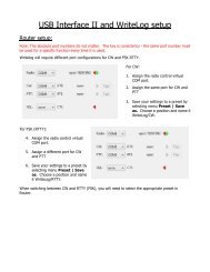
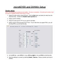
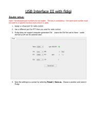
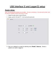
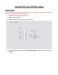
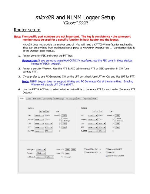
Router setup:micro2R and <strong>N1MM</strong> Logger Setup“Classic” SO2RNote: The specific port numbers are not important. The key is consistency - the same portnumber must be used for a specific function in both Router and the logger.micro2R does not provide transceiver control. You will need a CAT/CI-V interface for each radio.They can be anything from traditional serial ports to <strong>microHAM</strong> microKEYER II. Connection data isin the micro2R User Manual.1. Assign ports for FSK and check the PTT box.Suggestion: If you are using <strong>microHAM</strong> CAT/CI-V interfaces, use the FSK ports in those devicesinstead of FSK in micro2R.2. Assign a port for WinKey. Use the PTT & ACC tab to select PTT or QSK operation in CW (UseWinKey PTT).3. If you prefer to use PC Generated CW on the <strong>LPT</strong> port check Use <strong>LPT</strong> for CW and Use <strong>LPT</strong> for PTT.Note: <strong>N1MM</strong> Logger does not support WinKey and PC Generated CW at the same time. EnablingWinKey will disable <strong>LPT</strong> CW and PTT.4. Use the PTT & ACC tab to select whether micro2R is to generate PTT for each radio (Generate PTTOutput).
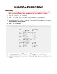
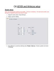
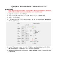
5. Select “Classic auto control” on the SO2R tab and assign the following controls:○ Pin 3 for TX focus○ Pin 4 for RX focus○ Pin 5 for Stereo HeadphonesThese settings allow <strong>N1MM</strong> Logger to control both transmit and receive focusautomatically. Stereo receive is commanded by the “`” (accent grave or unshifted tildekey) and the {STEREOON} and {STEREOOFF} macros.Antenna Relay is not supported in classic mode.6. Save the settings to a preset by selecting menu Preset | Save as. Choose a position and name it<strong>N1MM</strong>.<strong>N1MM</strong> hardware setup:1. Click Config | Configure Ports, Telent Addresses, Other ...2. Assign each radio to the virtual COM port you used in Router's Ports tab
3. For each radio port click Set and configure the proper communication parameters as required foryour CAT/CI-V interfaces. Do Not check “Radio PTT via command.”4. Configure the Digital ports taking care to associate each port with the correct Radio (Radio Nr) andDigital Interface (Dig Wind Nr).5. Set DTR to "always Off" and set RTS (pin 7) to PTT. PTT will be available in all modes.
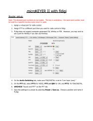
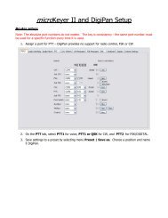
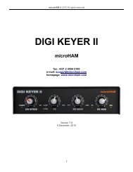
6. Assign a port for WinKey and set Radio Nr toBoth.Note: Do not configure a WinKey port if you willbe using computer generated CW from the <strong>LPT</strong>.7. Check CW/Other for the <strong>LPT</strong> port you willbe using for radio selection and click the Setbutton8. Set the correct Port Addr and set Radio Nr toBoth.9. Configure WinKey with the <strong>N1MM</strong>WinKey tab.10. Use 2 nd Output should be checked11. Pin 5 Function should be PTT12. Set Lead Time = 1Note: All of the WinKey timingparameters are controlled onRouter's CW/WinKey tab
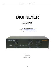
13. Configure Audio for"1 - Zero or Single Card,One Radio, No Sound CardSO2R"14. Select the soundcard youare using with micro2R asthe Output Device.15. Select microphone as thePort to Mute16. Select the soundcard youare using with micro2R asthe Message RecordingDevice.17. Select Microphone as theMessage Recording Port.NOTE: Selection of theQSO Recording Devicewill be dependent on yourdigital connection.18. Set Recording channels to Two (2) if you have connected both receivers to the Line input of thesound card being used for QSO Recording.NOTE: Other than setting the correct virtual port for FSK (if used) with MMTTY or MMVARI, the digitalconfiguration is identical to that used with your existing digital interface. The information below isprovided as a matter of convenience. Please refer to the <strong>N1MM</strong> Logger Help and documentationfor your particular interface when configuring digital mode support.NOTE: When using a micro2R FSK port for RTTY with MMVARI, the FSK Port setting must be FSK8250.
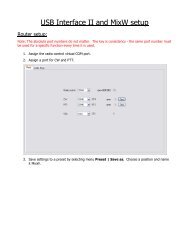
FSK with MMTTY:<strong>N1MM</strong> Logger supports the MMTTY Engine, MMVARI and/or an external TNC for RTTY contesting.This configuration is based on using MMTTY in FSK mode.1. Install MMTTY in two differentdirectories on your hard disk.2. Select the Digital Modes tab inthe <strong>N1MM</strong> Logger Configurer.3. Set TU Type to Soundcard4. Select FSK as the MMTTY modefor DI-1 and DI-2.5. Enter the path to each MMTTYinstallation.6. Open the Mode Controltab7. Set the appropriate RTTYand PSK modes for eachradio.Note: See the <strong>N1MM</strong>Logger Help files for thesupported RTTY and PSKmodes for your radios.8. Set the method todetermine the mode tolog.9. Click "OK" to save thesettings and close theConfigurer.
10. Activate the left Entry Window (Radio 1) and open the Digital Interface.11. If this is the first time you have used the MMTTY interface, click on Interface | MMTTY toactivate the MMTTY interface.12. In the Digital Interface, Click Setup | Setup MMTTY.13. Select the "SoundCard" tab.14. Select the sound card used forReception and Transmissionon Radio 1.15. Select the TX tab16. Set PTT & FSK to the portused for Router's Radio 1FSK port.17. Select the Misc Tab18. If the same sound card will beused with both radios, selectSource = Left19. Set Tx Port to COM-TxD(FSK)20. Click USB port button, choose C: Limiting speed and clickOK21. Click "OK" on the Misc tab to close the MMTTY Set-up forRadio 1
22. Activate the right Entry Window (Radio 2) and open the Digital Interface.23. Click on Interface | MMTTY to activate the MMTTY interface.24. In the Digital Interface, Click Setup | Setup MMTTY.25. Select the "SoundCard" tab.26. Select the sound card used forReception and Transmissionon Radio 2.27. Select the TX tab28. Set PTT & FSK to the portused for Router's Radio 2FSK port.29. Select the Misc Tab30. If the same sound card will beused with both radios, selectSource = Right31. Set Tx Port to COM-TxD(FSK)32. Click USB port button, choose C: Limiting speed and clickOK33. Click "OK" on the Misc tab to close the MMTTY Set-up forRadio 1
AFSK with MMTTY:<strong>N1MM</strong> Logger supports the MMTTY Engine, MMVARI and/or an external TNC for RTTY contesting.This configuration is based on using MMTTY in AFSK mode.AFSK does not require a digital port for each radio. If you will be using only AFSK and PSK, it is notnecessary to define "Digital" ports on the <strong>N1MM</strong> "Hardware" tab or FSK ports in Router.1. Install MMTTY in two differentdirectories on your hard disk.2. Select the Digital Modes tab inthe <strong>N1MM</strong> Logger Configurer.3. Set the TU Type to Soundcard4. select AFSK as the MMTTY modefor both DI-1 and DI-2.5. Enter the path to each copy ofMMTTY.6. Open the Mode Control tab7. Set the appropriate RTTY andPSK modes for each radio.Note: See the <strong>N1MM</strong> LoggerHelp files for the supportedRTTY and PSK modes for yourradios.8. Set the method to determinethe mode recorded in the log.9. Save and Close the Configurer.10. Activate the left Entry Window (Radio 1) and open the Digital Interface.11. If this is the first time you have used the MMTTY interface, click on Interface | MMTTY toactivate the MMTTY interface.12. In the Digital Interface, ClickSetup | Setup MMTTY.13. Select the "SoundCard" tab.14. Set Reception andTransmission to the soundcard used with Radio 1.
15. Select the Misc Tab16. Select Source = Left ifusing the same sound cardfor both radios17. Set Tx Port to Sound.18. Click "OK" to close MMTTYSet-up for Radio 119. Activate the right EntryWindow (Radio 2) andopen the Digital Interface.20. Click on Interface |MMTTY to activate theMMTTY interface.21. In the Digital Interface, ClickSetup | Setup MMTTY.22. Select the "SoundCard" tab.23. Set Reception andTransmission to the soundcard used with Radio 2.24. Select the Misc Tab25. Select Source = Right ifusing the same sound cardfor both radios26. Set Tx Port to Sound27. Click "OK" to close MMTTYSetup for Radio 2.
FSK/PSK31 with MMVARI:<strong>N1MM</strong> Logger supports the MMTTY Engine, MMVARI and/or an external TNC for RTTY contesting. Thisconfiguration is for FSK RTTY and PSK.FSK requires use of a digital port for each radio. Be sure you have defined Digital ports for each radio inthe <strong>N1MM</strong> "Hardware" tab and FSK ports in Router.1. Select the Digital Modestab in the <strong>N1MM</strong> LoggerConfigurer.2. Set the TU Type toSoundcard3. select FSK as the MMTTYRTTY mode for both DI-1and DI-2.4. Set the FSK Port toFSK8250 for both DI-1and DI-25. Open the Mode Controltab6. Set the appropriate RTTY andPSK modes for each radio.Note: See the <strong>N1MM</strong>Logger Help files for thesupported RTTY and PSKmodes for your radios.7. Set the method to determinethe mode recorded in the log.8. Save and Close the <strong>N1MM</strong>Configurer.
9. Activate the left Entry Window (Radio 1) and enter PSK.10. Click Setup | Settings. Select MMVARI as the Preferred RTTY Interface and Preferred PSK Interface.16. Save the configuration.17. Select RTTY-L mode in MMVARI in DI-118. Select the MMVARIFSK1 window from the Windows TaskBar.19. Set Port to the port you chose for Radio 1 FSK in Router20. Set PTT output to RTS21. Check Limiting Speed22. Return the MMVARIFSK1 window to the Task Bar.11. Select MMVARI Setup.12. Set DI1 MMVARI SoundCard Input Soundcard # tothe sound card used withRadio 1. Select Left if thesame sound card is usedfor both radios.13. Set DI1 MMVARI SoundCard Output Soundcard #to the sound card usedwith Radio 1.14. Set DI2 MMVARI SoundCard Input Soundcard # tothe sound card used withRadio 2. Select Right ifthe same sound card isused for both radios.15. Set DI1 MMVARI SoundCard Output Soundcard #to the sound card usedwith Radio 2.
23. Select DI-2 (Open the second DI if it is not already open)24. Select Interface | MMVARI if MMVARI is not alreadythe active interface25. Select RTTY-L mode in MMVARI.26. Select the MMVARIFSK2 window from the Windows TaskBar.27. Set Port to the port you chose for Radio 2 FSK in Router.28. Set PTT output to RTS29. Check Limiting Speed30. Return the MMVARIFSK2 window to the Task Bar.
AFSK/PSK31 with MMVARI:<strong>N1MM</strong> Logger supports the MMTTY Engine, MMVARI and/or an external TNC for RTTY contesting. Thisconfiguration is for AFSK RTTY and PSK.AFSK and PSK do not require the use of a digital port for each radio. Do not configure a Digital Port in<strong>N1MM</strong> Logger or a FSK Port in Router.1. Select the Digital Modestab in the <strong>N1MM</strong> LoggerConfigurer.2. Set the TU Type toSoundcard3. select AFSK as the MMTTYRTTY mode for both DI-1and DI-2.4. Open the Mode Controltab5. Set the appropriate RTTY andPSK modes for each radio.Note: See the <strong>N1MM</strong> LoggerHelp files for the supportedRTTY (AFSK) and PSK modesfor your radios.6. Set the method to determinethe mode recorded in the log.7. Save and Close the <strong>N1MM</strong>Configurer.
8. Activate the left Entry Window (Radio 1) and enter PSK.9. Click Setup | Settings. Select MMVARI as the Preferred RTTY Interface and Preferred PSK Interface.15. Save the configuration.10. Select MMVARI Setup.11. Set DI1 MMVARI SoundCard Input Soundcard # tothe sound card used withRadio 1. Select Left if thesame sound card will beused for both radios.12. Set DI1 MMVARI SoundCard Output Soundcard # tothe sound card used withRadio 1.13. Set DI2 MMVARI SoundCard Input Soundcard # tothe sound card used withRadio 2. Select Right if thesame sound card will beused for both radios.14. Set DI1 MMVARI SoundCard Output Soundcard # tothe sound card used withRadio 2.