Basics of steam generation
Basics of steam generation
Basics of steam generation

Create successful ePaper yourself
Turn your PDF publications into a flip-book with our unique Google optimized e-Paper software.
Helsinki University <strong>of</strong> Technology Department <strong>of</strong> Mechanical EngineeringEnergy Engineering and Environmental Protection PublicationsSteam Boiler Technology eBookEspoo 2002<strong>Basics</strong> <strong>of</strong> Steam GenerationSebastian TeirHelsinki University <strong>of</strong> TechnologyDepartment <strong>of</strong> Mechanical EngineeringEnergy Engineering and Environmental Protection
Table <strong>of</strong> contentsIntroduction..........................................................................................................................................3<strong>Basics</strong> <strong>of</strong> boilers and boiler processes..................................................................................................3Definition .........................................................................................................................................3A simple boiler.................................................................................................................................4A simple power plant cycle..............................................................................................................4Carnot efficiency..............................................................................................................................5Properties <strong>of</strong> water and <strong>steam</strong> ..........................................................................................................5Introduction..................................................................................................................................5Boiling <strong>of</strong> water ...........................................................................................................................6Effect <strong>of</strong> pressure on evaporation temperature ............................................................................7<strong>Basics</strong> <strong>of</strong> combustion .......................................................................................................................7Principles......................................................................................................................................7Products <strong>of</strong> combustion................................................................................................................8Types <strong>of</strong> combustion....................................................................................................................8Combustion <strong>of</strong> solid fuels ............................................................................................................8Combustion <strong>of</strong> coal ......................................................................................................................8Main types <strong>of</strong> a modern boiler .........................................................................................................9Heat exchanger boiler model .........................................................................................................10General.......................................................................................................................................10Heat exchanger basics................................................................................................................10T-Q diagram...............................................................................................................................11Heat recovery <strong>steam</strong> generator model........................................................................................12Heat exchanger model <strong>of</strong> furnace-equipped boilers ..................................................................13References......................................................................................................................................15The <strong>Basics</strong> <strong>of</strong> Steam Generation - 2
IntroductionThe world energy consumption has doubled in the last thirty years and it keeps on increasing withabout 1,5 % per year. While the earth's oil and gas reserves are expected to deplete after roughlyone hundred years, the coal reserves will last for almost five hundred years into the future. InFinland, 50 % <strong>of</strong> the electrical power produced, is produced in <strong>steam</strong> power plants. But there aremore reasons to why electricity <strong>generation</strong> based on <strong>steam</strong> power plant will continue to grow andwhy there still will be a demand for <strong>steam</strong> boilers in the future:• The cost <strong>of</strong> the produced electricity is low• The technology has been used for many decades and is reliable and available• Wind and solar power are still expensive compared to <strong>steam</strong> power• The environmental impact <strong>of</strong> coal powered <strong>steam</strong> plants have under the past decade beenheavily diminished thanks to improved SO x and NO x reduction technology• The paper industry uses <strong>steam</strong> boilers as a vital utility to recycle chemicals and deriveelectricity from black liquor (pulping waste)• Waste and bi<strong>of</strong>uels can effectively be combusted in a boiler<strong>Basics</strong> <strong>of</strong> boilers and boiler processesDefinitionIn a traditional context, a boiler is an enclosed container that provides a means for heat fromcombustion to be transferred into the working media (usually water) until it becomes heated or a gas(<strong>steam</strong>). One could simply say that a boiler is as a heat exchanger between fire and water. Theboiler is the part <strong>of</strong> a <strong>steam</strong> power plant process that produces the <strong>steam</strong> and thus provides the heat.The <strong>steam</strong> or hot water under pressure can then be used for transferring the heat to a process thatconsumes the heat in the <strong>steam</strong> and turns it into work. A <strong>steam</strong> boiler fulfils the followingstatements:• It is part <strong>of</strong> a type <strong>of</strong> heat engine or process• Heat is generated through combustion (burning)• It has a working fluid, a.k.a. heat carrier that transfers the generated heat away from theboiler• The heating media and working fluid are separated by wallsIn an industrial/technical context, the concept “<strong>steam</strong> boiler” (also referred to as “<strong>steam</strong> generator”)includes the whole complex system for producing <strong>steam</strong> for use e. g. in a turbine or in industrialprocess. It includes all the different phases <strong>of</strong> heat transfer from flames to water/<strong>steam</strong> mixture(economizer, boiler, superheater, reheater and air preheater). It also includes different auxiliarysystems (e. g. fuel feeding, water treatment, flue gas channels including stack). [1]The heat is generated in the furnace part <strong>of</strong> the boiler, where fuel is combusted. The fuel used in aboiler contains either chemically bonded energy (like coal, waste and bi<strong>of</strong>uels) or nuclear energy.Nuclear energy will not be covered in this material. A boiler must be designed to absorb themaximum amount <strong>of</strong> heat released in the process <strong>of</strong> combustion. This heat is transferred to theboiler water through radiation, conduction and convection. The relative percentage <strong>of</strong> each isdependent upon the type <strong>of</strong> boiler, the designed heat transfer surface and the fuels that power thecombustion.The <strong>Basics</strong> <strong>of</strong> Steam Generation - 3
expansion is the source <strong>of</strong> power in all <strong>steam</strong> engines. It also makes the boiler a dangerous devicethat must be carefully treated.The theoretical amount <strong>of</strong> heat that can betransferred from the combustion process tothe working fluid in a boiler is equivalentto the change in its total heat content fromits state at entering to that at exiting theboiler. In order to be able to select anddesign <strong>steam</strong>- and power-<strong>generation</strong>equipment, it is necessary to thoroughlyunderstand the properties <strong>of</strong> the workingfluid <strong>steam</strong>, the use <strong>of</strong> <strong>steam</strong> tables and theuse <strong>of</strong> superheat. These fundamentals <strong>of</strong><strong>steam</strong> <strong>generation</strong> will be briefly reviewedin this chapter. When phase changes <strong>of</strong> thewater is discussed, only the liquid-vaporand vapor-liquid phase changes arementioned, since these are the phasechanges that the entire boiler technology isbased on. [2]Temperature [C]180160140120100806040Evaporation <strong>of</strong> waterPhase change200 500 1000 1500 2000 2500 3000Net enthalpy <strong>of</strong> water [kJ/kg water]Figure 6: Water evaporation plotted in atemperature-enthalpy graph.Boiling <strong>of</strong> waterWater and <strong>steam</strong> are typically used as heat carriers in heating systems. Steam, the gas phase <strong>of</strong>water, results from adding sufficient heat to water to cause it to evaporate. This boiler processconsists <strong>of</strong> three main steps: The first step is the adding <strong>of</strong> heat to the water that raises thetemperature up to the boiling point <strong>of</strong> water, also called preheating. The second step is thecontinuing addition <strong>of</strong> heat to change the phase from water to <strong>steam</strong>, the actual evaporation. Thethird step is the heating <strong>of</strong> <strong>steam</strong> beyond the boiling temperature <strong>of</strong> water, known as superheating.The first step and the third steps are the part where heat addition causes a temperature rise but nophase change, and the second step is the part where the heat addition only causes a phase change. InFigure 6, the left section represents the preheating, the middle section the evaporation, and the thirdsection the superheating. When all the water has been evaporated, the <strong>steam</strong> is called dry saturated<strong>steam</strong>. If <strong>steam</strong> is heated beyond its saturation point, the temperature begins to rise again and the<strong>steam</strong> becomes superheated <strong>steam</strong>. Superheated <strong>steam</strong> is defined by its zero moisture content: Itcontains no water at all, only 100% <strong>steam</strong>.EvaporationDuring the evaporation the enthalpy rises drastically. If we evaporate the water at atmosphericpressure from saturated liquid to saturated vapour, the enthalpy rise needed is 2260 kJ/kg, from 430kJ/kg (sat. water) to 2690 kJ/kg (sat. <strong>steam</strong>). When the water has reached the dry saturated <strong>steam</strong>condition, the <strong>steam</strong> contains a large amount <strong>of</strong> latent heat, corresponding to the heat that was led tothe process under constant pressure and temperature. So despite pressure and temperature is thesame for the liquid and the vapour, the amount <strong>of</strong> heat is much higher in vapour compared to theliquid.SuperheatingIf the <strong>steam</strong> is heated beyond the dry saturated <strong>steam</strong> condition, the temperature begins to rise againand the properties <strong>of</strong> the <strong>steam</strong> start to resemble those <strong>of</strong> a perfect gas. Steam with higherThe <strong>Basics</strong> <strong>of</strong> Steam Generation - 6
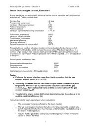
temperature than that <strong>of</strong> saturated <strong>steam</strong> is called superheated <strong>steam</strong>. It contains no moisture andcannot condense until its temperature has been lowered to that <strong>of</strong> saturated <strong>steam</strong> at the samepressure. Superheating the <strong>steam</strong> is particularly useful for eliminating condensation in <strong>steam</strong> lines,decreasing the moisture in the turbine exhaust and increasing the efficiency (i.e. Carnot efficiency)<strong>of</strong> the power plant.Effect <strong>of</strong> pressure on evaporation temperatureIt is well known that water boils andevaporates at 100°C under atmosphericpressure. By higher pressure, waterevaporates at higher temperature - e.g. apressure <strong>of</strong> 10 bar equals an evaporationtemperature <strong>of</strong> 184°C. The pressure and thecorresponding temperature when a phasechange occurs are called the saturationtemperature and saturation pressure. Duringthe evaporation process, pressure andtemperature are constant, but if thevaporization occurs in a closed vessel, theexpansion that occurs due to the phase change<strong>of</strong> water into <strong>steam</strong> causes the pressure to riseand thus the boiling temperature rises.From the diagram (Figure 7) we can se thatwhen we exceed a certain pressure, 22,12Mpa (the corresponding temperature is374°C), the line stops. The reason is that theborder between gas phase and liquid phase isblurred out at that pressure. That point, wherethe different phases cease to exist, is calledthe critical point <strong>of</strong> water.<strong>Basics</strong> <strong>of</strong> combustionPrinciplesThe process <strong>of</strong> combustion is a high speed, hightemperature chemical reaction. It is the rapidunion <strong>of</strong> an element or a compound with oxygenthat results in the production <strong>of</strong> heat -essentially, it is a controlled explosion.Combustion occurs when the elements in a fuelcombine with oxygen and produce heat. Allfuels, whether they are solid, liquid or ingaseous form, consist primarily <strong>of</strong> compounds<strong>of</strong> carbon and hydrogen called hydrocarbons.Sulphur is also present in these fuels.Pressure [bar]1000100100,10,0122,12 MPa10 100 200 300 400Temperature [°C]Figure 7: Evaporation pressure as a function <strong>of</strong>evaporation temperature.Figure 8: A pulverized coal fired burner inaction.The <strong>Basics</strong> <strong>of</strong> Steam Generation - 7
Products <strong>of</strong> combustionWhen the hydrogen and oxygen combine, intense heat and water vapor is formed. When carbon andoxygen combine, intense heat and the compounds <strong>of</strong> carbon monoxide or carbon dioxide areformed. When sulfur and oxygen combine, sulfur dioxide and heat are formed. These chemicalreactions take place in a furnace during the burning <strong>of</strong> fuel, provided there is sufficient air (oxygen)to completely burn the fuel. Very little <strong>of</strong> the released carbon is actually "consumed" in thecombustion reaction because flame temperature seldom reaches the vaporization point <strong>of</strong> carbon.Most <strong>of</strong> it combines with oxygen to form CO 2 and passes out the vent. Carbon, which cools beforeit can combine with oxygen to form CO 2 , passes out the vent as visible smoke. The intense yellowcolor <strong>of</strong> an oil flame is largely caused by incandescent carbon particles. As we mentioned in theintroduction to this segment, combustion can never be 100% efficient. All fuels contain somemoisture and non-combustibles:• Top-quality coal has 20% noncombustibles.• Residual oil is 10% noncombustible.• Natural gas has 1 - 15% (depending on origin) <strong>of</strong> noncombustible gases like N 2 and CO 2 .Types <strong>of</strong> combustionThere are three types <strong>of</strong> combustion:• Perfect Combustion is achieved when all the fuel is burned using only the theoreticalamount <strong>of</strong> air, but as we said before perfect combustion cannot be achieved in a boiler.• Complete Combustion is achieved when all the fuel is burned using the minimal amount <strong>of</strong>air above the theoretical amount <strong>of</strong> air needed to burn the fuel. Complete combustion isalways our goal. With complete combustion, the fuel is burned at the highest combustionefficiency with low pollution.• Incomplete Combustion occurs when all the fuel is not burned, which results in theformation <strong>of</strong> soot and smoke.Combustion <strong>of</strong> solid fuelsSolid fuels can be divided into high grade; coaland low grade; peat and bark. The most typicalfiring methods are grate firing, cyclone firing,pulverized firing and fluidized bed firing, asdescribed below. Pulverized firing has been usedin industrial and utility boilers from 60 MWt to6000 MWt. Grate firing (Figure 9) has beenused to fire bi<strong>of</strong>uels from 5 MWt to 600 MWtand cyclone firing has been used in small scale3-6 MWt.Figure 9: Stoker or grate firing.Combustion <strong>of</strong> coalOil and gas are always combusted with a burner, but there are three different ways to combust coal:The <strong>Basics</strong> <strong>of</strong> Steam Generation - 8
• Fluidized bed combustion• Fixed bed combustion (grate boilers)• Entrained bed combustion (pulverized coal combustion)In fixed bed combustion, larger-sized coal iscombusted in the bottom part <strong>of</strong> the combustor withlow-velocity air. Stoker boilers also employ this type<strong>of</strong> combustion. Large-capacity pulverized coal firedboilers for power plants usually employ entrained bedcombustion. In fluidized bed combustion, fuel isintroduced into the fluidized bed and combusted.Main types <strong>of</strong> a modern boilerIn a modern boiler, there are two main types <strong>of</strong> boilerswhen considering the heat transfer means from fluegases to feed water: Fire tube boilers and water tubeboilers.In a fire tube boiler the flue gases from the furnace areconducted to flue passages, which consist <strong>of</strong> severalparallel-connected tubes. The tubes run through theboiler vessel, which contains the feedwater. The tubesare thus surrounded by water. The heat from the fluegases is transferred from the tubes to the water in thecontainer, thus the water is heated into <strong>steam</strong>. An easyway to remember the principle is to say that a fire tubeboiler has "fire in the tubes".Figure 10: Fluidized bed combustion.1. Turning chamber2. Flue gas collectionchamber3. Open furnace4. Flame tube5. Burner seat6. Manhole7. Fire tubes8. Water space9. Steam space10. Outlet and circulation11. Flue gas out12. Blow-out hatch13. Main hatch14. Cleaning hatch15. Main <strong>steam</strong> outlet16. Level control assembly17. Feedwater inlet18. Utility <strong>steam</strong> outlet19. Safety valve assembly20. Feet21. InslulationFigure 11: Schematic <strong>of</strong> a Höyrytys TTK fire tube <strong>steam</strong> boiler [Höyrytys].The <strong>Basics</strong> <strong>of</strong> Steam Generation - 9
In a water tube boiler, the conditions are theopposite <strong>of</strong> a fire tube boiler. The watercirculates in many parallel-connected tubes. Thetubes are situated in the flue gas channel, and areheated by the flue gases, which are led from thefurnace through the flue gas passage. In amodern boiler, the tubes, where water circulates,are welded together and form the furnace walls.Therefore the water tubes are directly exposed toradiation and gases from the combustion (Figure12). Similarly to the fire tube boiler, the watertube boiler received its name from having "waterin the tubes".A modern utility boiler is usually a water tubeboiler, because a fire tube boiler is limited incapacity and only feasible in small systems.Figure 12: Simplified drawing describing thewater tube boiler principle. /4/Heat exchanger boiler modelGeneralIf a modern water tube boiler utilizes a furnace,the furnace and the evaporator is usually thesame construction – the inner furnace wallsconsists solely <strong>of</strong> boiler tubes, conducting feedwater, which absorbs the combustion heat andevaporates.flue gasprocess <strong>steam</strong>In process engineering a boiler is modelled as anetwork <strong>of</strong> heat exchangers, which symbolizesthe transfer <strong>of</strong> heat from the flue gas to the<strong>steam</strong>/water in boiler pipes.For instance, the furnace, abstracted as a heatexchanger (Figure 13), consists <strong>of</strong> the followingstreams: the fuel (at storage temperature),combustion air (at outdoors temperature) andfeedwater as input streams. The output streamsare the flue gas from the combustion <strong>of</strong> the fuelairmixture, and the <strong>steam</strong>.feed waterairfuelFigure 13: Furnace heat exchanger model.Heat exchanger basicsThe task <strong>of</strong> a heat exchanger is to transfer the heat from one flow <strong>of</strong> medium (fluid/gas stream) toanother - without any physical contact, i.e. without actually mixing the two media. When speakingabout the two streams that interact (exchange heat) in a heat exchanger we usually talk about the hotstream and the cold stream (Figure 14). The hot stream (a.k.a. heat source) is the stream that givesaway heat to the cold stream (a.k.a. heat sink) that absorbs the heat. Thus, in a boiler the flue gasstream is the hot stream (heat source) and the water/<strong>steam</strong> stream is the cold stream (heat sink).The <strong>Basics</strong> <strong>of</strong> Steam Generation - 10
There are two different main types <strong>of</strong> heatexchangers: Parallel-flow and counter-flow. In aparallel flow heat exchanger the fluids flow inthe same direction and in a counter flow heatexchanger the fluids flow in the oppositedirection. Combinations <strong>of</strong> these types (likecross-flow exchangers and more complicatedones, like boilers) can usually be approximatelycalculated according to the counter-flow type.hot streamcold streamT-Q diagramA useful tool for designing a heat exchanger isthe T-Q diagram. The diagram consists <strong>of</strong> twoaxes: Temperature (T) and transferred heat (Q).The hot stream and the cold stream arerepresented in the diagram by two lines on top<strong>of</strong> each other. If the exchanger is <strong>of</strong> parallelflowtype, the lines proceed in the samedirection (Figure 15). If the exchanger is acounter-flow (or cross-flow-combination, like aboiler), the lines points in the opposite direction(Figure 16). The length <strong>of</strong> the lines on the Q-axis shows the transferred heat rate and the T-axis the rise/drop in temperature that the heattransfer has caused.Since the heat strays from a higher temperatureto a lower (according to the second law <strong>of</strong>thermodynamics) the wanted heat transferhappens by itself if and only if the hot stream isalways hotter than the cold stream. That's whythe streams must never cross. Since no materialhas an infinite heat transfer rate, the “pinchtemperature” (Tpinch) <strong>of</strong> the heat exchangerdefines the minimum allowed temperaturedifference between the two flows.If the streams cross, the lines must behorizontally adjusted (that is, external heatingand cooling must be supplied) in order tocorrespond with the pinch temperature (Figure17).Figure 14: A heat exchanger (also furnace).T1T2t2t1Thot streamcold streamFigure 15: T-Q diagram <strong>of</strong> a parallel-flow typeheat exchanger.T1T2t2t1TdeltaQFigure 16: T-Q diagram <strong>of</strong> a counter-flow typeheat exchanger.QQThe <strong>Basics</strong> <strong>of</strong> Steam Generation - 11
Tt1T1TpinchT2t1Qexternal heatingrequiredexternal coolingrequiredFigure 17: Adjusted streams.Heat recovery <strong>steam</strong> generator modelTo give an example <strong>of</strong> the construction <strong>of</strong> a heat exchanger model, a heat recovery <strong>steam</strong> generator(HRSG) is constructed next as a heat exchanger cascade. The HRSG is basically a boiler without afurnace – the HRSG extracts heat from flue gases originating from fuel combusted in an externalunit. Since the HRSG only deals with two streams (flue gases as the hot stream and <strong>steam</strong>/water asthe cold stream), it represents the simplest heat exchanger model <strong>of</strong> a modern boiler application.Since the heating <strong>of</strong> water occurs in three steps (Figure 6), the heat exchanger model is usuallydivided into at least three units.We start with the heat exchanger unit, where the evaporation occurs – the evaporator. Assumingthat water enters the evaporator as saturated water and exits as saturated <strong>steam</strong>, the heat transferredfrom the flue gas is the required heat to change the phase <strong>of</strong> water into <strong>steam</strong>. The phase changeoccurs (water boils) at a constant temperature, and therefore the <strong>steam</strong>/water stream temperaturewon’t change in the evaporator.In order to preheat the water for the evaporator, another heat exchanger unit is needed. This unit iscalled economizer, and is a cross-flow type <strong>of</strong> heat exchanger. It is placed after the evaporator in theflue gas stream, since the evaporator requires higher flue gas temperature than the economizer.The heat exchanger unit that superheats the saturated <strong>steam</strong> is called superheater. The superheaterheats the saturated <strong>steam</strong> beyond the saturation point until it reaches the designed maximumtemperature. It requires therefore the highest flue gas temperature to receive heat and is thus placedfirst in the flue gas stream. The maximum temperature <strong>of</strong> the boiler is limited by the properties <strong>of</strong>The <strong>Basics</strong> <strong>of</strong> Steam Generation - 12
the superheater tube material. Today's economically feasible material can take temperatures <strong>of</strong> 550-600 °C.The result is a heat exchanger cascade <strong>of</strong> a HRSG (with a single pressure level), which can be foundin Figure 18. The T-Q diagram <strong>of</strong> the model is visualized in Figure 19.EconomizerwatersaturatedwaterEvaporatorTSupEvaEcosaturated<strong>steam</strong>SuperheaterFigure 18: Heat exchanger model <strong>of</strong> the HRSG.Figure 19: T-Q diagram <strong>of</strong> the HRSG model inFigure 18.QHeat exchanger model <strong>of</strong> furnace-equipped boilersThe order <strong>of</strong> the heat transfer units on the water/<strong>steam</strong> side is always economizer - evaporator -superheater (downstream order). The temperature levels and the temperature difference between theflue gases and the working fluid usually limits the arrangement variation possibilities <strong>of</strong> the heattransfer surfaces on the flue gas side.In a boiler with a furnace, adequate cooling has to be maintained and material temperature shouldnot exceed 600°C. Thus the evaporator part <strong>of</strong> the water/<strong>steam</strong> cycle is placed in the furnace walls,since the heat <strong>of</strong> the evaporation provides enough cooling for the furnace, which is the hottest part<strong>of</strong> the boiler.Since the furnace is inside the boiler, high flue gas temperatures (over 1000°C) are obtained. Afterthe flue gas has given <strong>of</strong>f heat for the <strong>steam</strong> production, it is still quite hot. In order to cool downthe flue gases further to gain higher boiler efficiency, flue gases can be used to preheat thecombustion air. The heat exchanger used for this purpose is called an air preheater.The <strong>Basics</strong> <strong>of</strong> Steam Generation - 13
The result is a heat exchanger model <strong>of</strong> a furnace-equipped boiler (e.g. PCF-boiler, grate boiler oroil/gas boiler), which can be found in Figure 20. The T-Q diagram <strong>of</strong> the model is visualized inFigure 21Air outTEcoEva Sup AirAir inAir preheaterFigure 21: T-Q diagram <strong>of</strong> the heat exchangermodel in Figure 20.QFigure 20: Furnace equipped boiler with airpreheater.The <strong>Basics</strong> <strong>of</strong> Steam Generation - 14
References1. Ahonen, V. “Höyrytekniikka II”. Otakustantamo, Espoo. 1978.2. Combustion Engineering. ”Combustion: Fossil power systems”. 3 rd ed. Windsor. 1981.3. Esa Vakkilainen, lecture slides and material on <strong>steam</strong> boiler technology, 20014. American Heritage ® Dictionary <strong>of</strong> the English Language: Fourth Edition,http://www.bartleby.comThe <strong>Basics</strong> <strong>of</strong> Steam Generation - 15