Piezoelectrics in Positioning - PZT & Piezo Actuators: Sub ...
Piezoelectrics in Positioning - PZT & Piezo Actuators: Sub ...
Piezoelectrics in Positioning - PZT & Piezo Actuators: Sub ...

You also want an ePaper? Increase the reach of your titles
YUMPU automatically turns print PDFs into web optimized ePapers that Google loves.
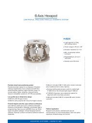
<strong>Piezo</strong> • Nano • Position<strong>in</strong>gContents<strong><strong>Piezo</strong>electrics</strong> <strong>in</strong> Position<strong>in</strong>gContents ............................................................2-172Features and Applications of <strong>Piezo</strong>electric Position<strong>in</strong>g Systems ..............2-174Glossary ............................................................2-175Introduction .........................................................2-177Nanoposition<strong>in</strong>g with <strong>Piezo</strong>electric Technology ............................2-177Features of <strong>Piezo</strong>electric <strong>Actuators</strong> ......................................2-177Quick Facts ..........................................................2-178ActuatorDesigns .....................................................2-178Operat<strong>in</strong>g Characteristics of <strong>Piezo</strong>electric <strong>Actuators</strong> ........................2-179Fundamentals of <strong>Piezo</strong>electricity ........................................2-181Material Properties ...................................................2-181<strong>PZT</strong> Ceramics Manufactur<strong>in</strong>g Process ....................................2-182Def<strong>in</strong>ition of <strong>Piezo</strong>electric Coefficients and Directions .......................2-182Resolution ...........................................................2-183Fundamentals of <strong>Piezo</strong>mechanics .......................................2-184Displacement of <strong>Piezo</strong> <strong>Actuators</strong> (Stack & Contraction Type) .................2-184Hysteresis (Open-Loop <strong>Piezo</strong> Operation) ..................................2-185Creep / Drift (Open-Loop <strong>Piezo</strong> Operation) ................................2-186Ag<strong>in</strong>g...............................................................2-186© Physik Instrumente (PI) GmbH & Co. KG 2008. <strong>Sub</strong>ject to change without notice.Cat120E Inspirations2009 08/10.18<strong>Actuators</strong> and Sensors ................................................2-187Metrology for Nanoposition<strong>in</strong>g Systems .................................2-187Indirect (Inferred) Metrology ............................................2-187Direct Metrology .....................................................2-187Parallel and Serial Metrology ...........................................2-187High-Resolution Sensors—Stra<strong>in</strong> Gauge Sensors ..........................2-187L<strong>in</strong>ear Variable Differential Transformers (LVDTs) ..........................2-188Capacitive Position Sensors ...........................................2-188Fundamentals of <strong>Piezo</strong>electric <strong>Actuators</strong> .................................2-189Forces and Stiffness ..................................................2-189Maximum Applicable Forces (Compressive Load Limit, Tensile Load Limit) ....2-189Stiffness ............................................................2-189Force Generation .....................................................2-190Displacement and External Forces .......................................2-191Dynamic Operation Fundamentals ......................................2-192Dynamic Forces ......................................................2-192Resonant Frequency ..................................................2-193How Fast Can a <strong>Piezo</strong> Actuator Expand? ..................................2-1942-172
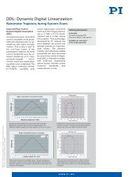
<strong>Piezo</strong> • Nano • Position<strong>in</strong>g<strong>Piezo</strong> Actuator Electrical Fundamentals ..................................2-195Electrical Requirements for <strong>Piezo</strong> Operation ...............................2-195Static Operation ......................................................2-195Dynamic Operation (L<strong>in</strong>ear) ............................................2-196Dynamic Operat<strong>in</strong>g Current Coefficient (DOCC) ............................2-197Dynamic Operation (Switched) ..........................................2-197Heat Generation <strong>in</strong> a <strong>Piezo</strong> Actuator <strong>in</strong> Dynamic Operation ..................2-198Control of <strong>Piezo</strong> <strong>Actuators</strong> and Stages ...................................2-199Position Servo-Control ................................................2-199Open- and Closed-Loop Resolution ......................................2-200<strong>Piezo</strong> Metrology Protocol ..............................................2-200Methods to Improve <strong>Piezo</strong> Dynamics ....................................2-201InputShap<strong>in</strong>g ® .......................................................2-201Signal Preshap<strong>in</strong>g / Dynamic Digital L<strong>in</strong>earization (DDL) ....................2-202Dynamic Digital L<strong>in</strong>earization (DDL) .....................................2-203Environmental Conditions and Influences ................................2-204Temperature Effects ...................................................2-204L<strong>in</strong>ear Thermal Expansion .............................................2-204Temperature Dependency of the <strong>Piezo</strong> Effect ..............................2-204<strong>Piezo</strong> Operation <strong>in</strong> High Humidity .......................................2-204<strong>Piezo</strong> Operation <strong>in</strong> Inert Gas Atmospheres ................................2-205Vacuum Operation of <strong>Piezo</strong> <strong>Actuators</strong> ....................................2-205Lifetimeof<strong>Piezo</strong><strong>Actuators</strong> .............................................2-206L<strong>in</strong>ear <strong>Actuators</strong> & MotorsNanoposition<strong>in</strong>g / <strong><strong>Piezo</strong>electrics</strong><strong>Piezo</strong> Flexure Stages /High-Speed Scann<strong>in</strong>g SystemsL<strong>in</strong>earVertical & Tip/Tilt2- and 3-Axis6-AxisFast Steer<strong>in</strong>g Mirrors /Active Optics<strong>Piezo</strong> Drivers /Servo ControllersS<strong>in</strong>gle-ChannelMulti-ChannelModularAccessories<strong><strong>Piezo</strong>electrics</strong> <strong>in</strong> Position<strong>in</strong>gNanometrologyMicroposition<strong>in</strong>gIndexBasic Designs of <strong>Piezo</strong>electric Position<strong>in</strong>g Drives/Systems ..................2-207Stack Design (Translators) .............................................2-207Lam<strong>in</strong>ar Design (Contraction-Type <strong>Actuators</strong>) .............................2-207TubeDesign .........................................................2-208Bender Type <strong>Actuators</strong> (Bimorph and Multimorph Design) ..................2-209Shear <strong>Actuators</strong> ......................................................2-209<strong>Piezo</strong> <strong>Actuators</strong> with Integrated Lever Motion Amplifiers ....................2-210<strong>Piezo</strong> Flexure Nanopositioners ..........................................2-211Parallel and Serial K<strong>in</strong>ematics / Metrology ...............................2-212Direct and Indirect Metrology ..........................................2-212Parallel and Serial K<strong>in</strong>ematics ..........................................2-213PMN Compared to <strong>PZT</strong> ................................................2-214Electrostrictive<strong>Actuators</strong>(PMN) ........................................2-214Summary ...........................................................2-215Mount<strong>in</strong>g and Handl<strong>in</strong>g Guidel<strong>in</strong>es for <strong>Piezo</strong> Translators ...................2-216SymbolsandUnits ...................................................2-2172-173
<strong>Piezo</strong> • Nano • Position<strong>in</strong>gProperties / ApplicationsFeatures of <strong>Piezo</strong>electric Position<strong>in</strong>g SystemsUnlimited Resolution<strong>Piezo</strong>electric actuators convertelectrical energy directly to mechanicalenergy. They make motion<strong>in</strong> the sub-nanometer rangepossible. There are no mov<strong>in</strong>gparts <strong>in</strong> contact with each other tolimit resolution.Fast Expansion<strong>Piezo</strong> actuators react <strong>in</strong> a matter ofmicroseconds. Acceleration ratesof more than 10,000 g can be obta<strong>in</strong>ed.High Force GenerationHigh-load piezo actuators capableof mov<strong>in</strong>g loads of several tons areavailable today. They can covertravel ranges of several 100 μmwith resolutions <strong>in</strong> the sub-nanometerrange (see examples likethe P-056, <strong>in</strong> the “<strong>Piezo</strong> <strong>Actuators</strong>& Components” section).No Magnetic FieldsThe piezoelectric effect is related toelectric fields. <strong>Piezo</strong> actuators donot produce magnetic fields norare they affected by them. <strong>Piezo</strong>devices are especially well suitedfor applications where magneticfields cannot be tolerated.Low Power ConsumptionStatic operation, even hold<strong>in</strong>gheavy loads for long periods, consumesvirtually no power. A piezoactuator behaves very much like anelectrical capacitor. When at rest,no heat is generated.No Wear and TearA piezo actuator has no mov<strong>in</strong>gparts like gears or bear<strong>in</strong>gs. Its displacementis based on solid statedynamics and shows no wear andtear. PI has conducted endurancetests on piezo actuators <strong>in</strong> whichno measurable change <strong>in</strong> performancewas observed after severalbillion cycles.Vacuum and Clean RoomCompatible<strong>Piezo</strong>electric actuators neithercause wear nor require lubricants.The new PICMA ® actuators withceramic <strong>in</strong>sulation have no polymercoat<strong>in</strong>g and are thus ideal forUHV (ultra-high vacuum) applications.Operation at CryogenicTemperaturesThe piezoelectric effect cont<strong>in</strong>uesto operate even at temperaturesclose to 0 kelv<strong>in</strong>. PI offers speciallyprepared actuators for use at cryogenictemperatures.<strong>Piezo</strong>electric nanoposition<strong>in</strong>g systems large(e.g. for precision mach<strong>in</strong><strong>in</strong>g), medium (e.g. for<strong>in</strong>terferometry), small (e.g. for data storagemedium test<strong>in</strong>g)Applications for <strong>Piezo</strong> Position<strong>in</strong>g Technology© Physik Instrumente (PI) GmbH & Co. KG 2008. <strong>Sub</strong>ject to change without notice.Cat120E Inspirations2009 08/10.182-174Data Storage MR head test<strong>in</strong>g Sp<strong>in</strong> stands Disk test<strong>in</strong>g Active vibration cancellation Pole-tip recession testSemiconductors, Microelectronics Nano & Microlithography Nanometrologie Wafer and mask position<strong>in</strong>g Critical-dimension-test Inspection systems Active vibration cancellationPrecision Mechanics Fast tool servos Non-circular gr<strong>in</strong>d<strong>in</strong>g,drill<strong>in</strong>g, turn<strong>in</strong>g Active vibration cancellation Structural deformation Tool adjustment Wear compensation Needle-valve actuation Micropumps L<strong>in</strong>ear drives Knife edge control <strong>in</strong> extrusiontools Micro engrav<strong>in</strong>g systems Shock wave generationLife Science, Medical Technology Scann<strong>in</strong>g microscopy Patch clamp Nanoliter pumps Gene manipulation Micromanipulation Cell penetration MicrodispensersOptics, Photonics,Nanometrologie Scann<strong>in</strong>g mirrors Image stabilization,pixel multiplication Scann<strong>in</strong>g microscopy Auto focus systems Interferometry Fiber optic alignment Fiber optics switch<strong>in</strong>g Adaptive and active optics Laser tun<strong>in</strong>g Stimulation of vibrationsSelection of piezo nanoposition<strong>in</strong>g stages
<strong>Piezo</strong> • Nano • Position<strong>in</strong>gGlossarySee also the Microposition<strong>in</strong>gFundamentals Glossary (p. 4-128).Actuator:A device that can produce force ormotion (displacement).Blocked Force:The maximum force an actuatorcan generate if blocked by an <strong>in</strong>f<strong>in</strong>itelyrigid restra<strong>in</strong>t.Ceramic:A polycrystall<strong>in</strong>e, <strong>in</strong>organic material.Closed-Loop Operation:The displacement of the actuatoris corrected by a servo-controllercompensat<strong>in</strong>g for nonl<strong>in</strong>earity,hysteresis and creep. See also“Open-Loop Operation“.Compliance:Displacement produced per unitforce. The reciprocal of stiffness.Creep:An unwanted change <strong>in</strong> the displacementover time.Curie Temperature:The temperature at which thecrystall<strong>in</strong>e structure changes froma piezoelectric (non-symmetrical)to a non-piezoelectric (symmetrical)form. At this temperature <strong>PZT</strong>ceramics looses the piezoelectricproperties.Drift:See “creep”Doma<strong>in</strong>:A region of electric dipoles withsimilar orientation.HV<strong>PZT</strong>:Acronym for High-Voltage <strong>PZT</strong>(actuator).<strong>Piezo</strong>ceramic layers <strong>in</strong> a “classical”stack actuator (HV<strong>PZT</strong>).Hysteresis:Hysteresis <strong>in</strong> piezo actuators isbased on crystall<strong>in</strong>e polarizationand molecular effects and occurswhen revers<strong>in</strong>g driv<strong>in</strong>g direction.Hysteresis is not to be confusedwith backlash.LV<strong>PZT</strong>:Acronym for low-voltage <strong>PZT</strong>(actuator).<strong>Piezo</strong>ceramic layers <strong>in</strong> a monolithicactuator (LV<strong>PZT</strong>).Monolithic Multilayer Actuator:An actuator manufactured <strong>in</strong> afashion similar to multilayer ceramiccapacitors. Ceramic andelectrode material are cofired <strong>in</strong>one step. Layer thickness is typicallyon the order of 20 to 100 μm.Open-Loop Operation:The actuator is used without aposition sensor. Displacementroughly corresponds to the drivevoltage. Creep, nonl<strong>in</strong>earity andhysteresis rema<strong>in</strong> uncompensated.Parallel K<strong>in</strong>ematics:Unlike <strong>in</strong> serial k<strong>in</strong>ematics designs,all actuators act upon thesame mov<strong>in</strong>g platform. Advantages:M<strong>in</strong>imized <strong>in</strong>ertia, nomov<strong>in</strong>g cables, lower center ofL<strong>in</strong>ear <strong>Actuators</strong> & MotorsNanoposition<strong>in</strong>g / <strong><strong>Piezo</strong>electrics</strong><strong>Piezo</strong> Flexure Stages /High-Speed Scann<strong>in</strong>g SystemsL<strong>in</strong>earVertical & Tip/Tilt2- and 3-Axis6-AxisFast Steer<strong>in</strong>g Mirrors /Active Optics<strong>Piezo</strong> Drivers /Servo ControllersS<strong>in</strong>gle-ChannelMulti-ChannelModularAccessories<strong><strong>Piezo</strong>electrics</strong> <strong>in</strong> Position<strong>in</strong>gNanometrologyMicroposition<strong>in</strong>gIndexNanoposition<strong>in</strong>g system featur<strong>in</strong>g parallelk<strong>in</strong>ematics and parallel metrology.Equipment for fully automated screen pr<strong>in</strong>t<strong>in</strong>g of electrodes on piezoelectric and dielectric ceramics.gravity, no cumulative guid<strong>in</strong>gerrors and more-compact construction.2-175
<strong>Piezo</strong> • Nano • Position<strong>in</strong>gGlossary (cont.)Parallel Metrology:Unlike <strong>in</strong> serial metrology designs,each sensor measures the positionof the same mov<strong>in</strong>g platform <strong>in</strong> therespective degree of freedom. Thiskeeps the off-axis runout of allactuators <strong>in</strong>side the servo-controlloop and allows it to be correctedautomatically (active guidance).<strong>Piezo</strong>electric Materials:Materials that change their dimensionswhen a voltage is appliedand produce a charge when pressureis applied.Metrology” is not possible, cumulativeguid<strong>in</strong>g errors, lower accuracy.Serial Metrology:One sensor is assigned to eachdegree of freedom to be servo-controlled.Undesired off-axis motion(guid<strong>in</strong>g error) from other axes <strong>in</strong>the direction of a given sensor, gounrecognized and uncorrected (seealso “Parallel Metrology”).Stiffness:Spr<strong>in</strong>g constant (for piezoelectricmaterials, not l<strong>in</strong>ear).Pol<strong>in</strong>g / Polarization:The procedure by which the bulkmaterial is made to take on piezoelectricproperties, i.e. the electricalalignment of the unit cells <strong>in</strong> a piezoelectricmaterial.<strong>PZT</strong>:Acronym for plumbum (lead) zirconatetitanate. Polycrystall<strong>in</strong>e ceramicmaterial with piezoelectricproperties. Often also used to referto a piezo actuator or translator.© Physik Instrumente (PI) GmbH & Co. KG 2008. <strong>Sub</strong>ject to change without notice.Cat120E Inspirations2009 08/10.182-176Serial K<strong>in</strong>ematics:Unlike <strong>in</strong> parallel k<strong>in</strong>ematics designs,each actuator acts upon aseparate platform of its own. Thereis a clear relationship betweenactuators and axes.Advantages: Simpler to assemble;simpler control algorithm.Disadvantages: Poorer dynamiccharacteristics, <strong>in</strong>tegrated “ParallelDesign pr<strong>in</strong>ciple of a stacked XY piezo stage(serial k<strong>in</strong>ematics).Flatness of a nanoposition<strong>in</strong>g stage with active trajectory control is better than1 nanometer over a 100 x 100 μm scann<strong>in</strong>g range.Trajectory-Control:Provisions to prevent deviationfrom the specified trajectory. Canbe passive (e.g. flexure guidance)or active (e.g. us<strong>in</strong>g additional activeaxes).Translator:A l<strong>in</strong>ear actuator.
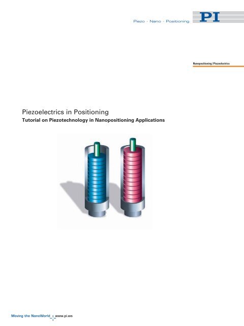
<strong>Piezo</strong> • Nano • Position<strong>in</strong>gIntroductionNanoposition<strong>in</strong>g with <strong>Piezo</strong>electric TechnologyBasicsThe piezoelectric effect is often encountered<strong>in</strong> daily life, for example<strong>in</strong> lighters, loudspeakers andbuzzers. In a gas lighter, pressureon a piezoceramic generates anelectric potential high enough tocreate a spark. Most electronicalarm clocks do not use electromagneticbuzzers anymore,because piezoelectric ceramicsare more compact and more efficient.In addition to such simpleapplications, piezo technology hasrecently established itself <strong>in</strong> theautomotive branch. <strong>Piezo</strong>-driven<strong>in</strong>jection valves <strong>in</strong> diesel eng<strong>in</strong>esrequire much lower transitiontimes than conventional electromagneticvalves, provid<strong>in</strong>g quieteroperation and lower emissions.The term “piezo” is derived fromthe Greek word for pressure. In1880 Jacques and Pierre Curie discoveredthat an electric potentialcould be generated by apply<strong>in</strong>gpressure to quarz crystals; theynamed this phenomenon the“piezo effect”. Later they ascerta<strong>in</strong>edthat when exposed to anelectric potential, piezoelectricmaterials change shape. This theynamed the “<strong>in</strong>verse piezo effect”.The first commercial applicationsof the <strong>in</strong>verse piezo effect were forsonar systems that were used <strong>in</strong>World War I. A breakthrough wasmade <strong>in</strong> the 1940’s when scientistsdiscovered that barium titanatecould be bestowed with piezoelectricproperties by expos<strong>in</strong>g it to anelectric field.Features of <strong>Piezo</strong>electric<strong>Actuators</strong> <strong>Piezo</strong> actuators can performsub-nanometer moves athigh frequencies becausethey derive their motionfrom solid-state crystal<strong>in</strong>eeffects. They have no rotat<strong>in</strong>gor slid<strong>in</strong>g parts to causefriction <strong>Piezo</strong> actuators can movehigh loads, up to severaltons <strong>Piezo</strong> actuators presentcapacitive loads and dissipatevirtually no power <strong>in</strong>static operation <strong>Piezo</strong> actuators require noma<strong>in</strong>tenance and are notsubject to wear because theyhave no mov<strong>in</strong>g parts <strong>in</strong> theclassical sense of the term<strong>Piezo</strong>electric materials are used toconvert electrical energy to mechanicalenergy and vice-versa. Theprecise motion that results whenan electric potential is applied to apiezoelectric material is of primordialimportance for nanoposition<strong>in</strong>g.<strong>Actuators</strong> us<strong>in</strong>g the piezoeffect have been commerciallyavailable for 35 years and <strong>in</strong> thattime have transformed the worldof precision position<strong>in</strong>g andmotion control.L<strong>in</strong>ear <strong>Actuators</strong> & MotorsNanoposition<strong>in</strong>g / <strong><strong>Piezo</strong>electrics</strong><strong>Piezo</strong> Flexure Stages /High-Speed Scann<strong>in</strong>g SystemsL<strong>in</strong>earVertical & Tip/Tilt2- and 3-Axis6-AxisFast Steer<strong>in</strong>g Mirrors /Active Optics<strong>Piezo</strong> Drivers /Servo ControllersS<strong>in</strong>gle-ChannelMulti-ChannelModularAccessories<strong><strong>Piezo</strong>electrics</strong> <strong>in</strong> Position<strong>in</strong>gNanometrologyMicroposition<strong>in</strong>gIndex2-177
<strong>Piezo</strong> • Nano • Position<strong>in</strong>gQuick FactsActuator DesignsNoteThis section gives a brief summaryof the properties of piezoelectricdrives and their applications. Fordetailed <strong>in</strong>formation, see “Fundamentalsof <strong>Piezo</strong>electricity” beg<strong>in</strong>n<strong>in</strong>gon p. 2-181.Stack actuators are the most commonand can generate the highestforces. Units with travel ranges upto 500 μm are available. To protectthe piezoceramic aga<strong>in</strong>st destructiveexternal conditions, they areoften provided with a metal cas<strong>in</strong>gand an <strong>in</strong>tegrated preload spr<strong>in</strong>g toabsorb tensile forces.times the displacement of the piezoelement, result<strong>in</strong>g <strong>in</strong> a travel rangeof several hundred μm.<strong>Piezo</strong>motors are used where evenlonger travel ranges are required.<strong>Piezo</strong>motors can be divided <strong>in</strong>totwo ma<strong>in</strong> categories: Ultrasonic Motors (Fig. 2a) <strong>Piezo</strong>-Walk ® Motors (Fig. 2b)The motion of ultrasonic piezomotorsis based on the frictionbetween parts oscillat<strong>in</strong>g withmicroscopic amplitudes. L<strong>in</strong>earultrasonic motors are very compactand can atta<strong>in</strong> high speeds comb<strong>in</strong>edwith resolutions of 0.1 μm orbetter. Rotary motors feature hightorques even at low rpm.<strong>Piezo</strong>-Walk ® l<strong>in</strong>ear drives (seep. 1-3 ff ) offer high position<strong>in</strong>g andhold<strong>in</strong>g forces (up to hundreds ofnewtons) with moderate speedsand resolutions <strong>in</strong> the subnanometerrange.All implementations are self-lock<strong>in</strong>gwhen powered down.<strong>Piezo</strong> tube actuators exploit theradial contraction direction, andare often used <strong>in</strong> scann<strong>in</strong>g microscopesand micropumps.Bender and bimorph actuatorsachieve travel ranges <strong>in</strong> the millimeterrange (despite their compactsize) but with relatively lowforce generation (a few newtons).Shear elements use the <strong>in</strong>versepiezo-effectshear component andachieve long travel and high force.© Physik Instrumente (PI) GmbH & Co. KG 2008. <strong>Sub</strong>ject to change without notice.Cat120E Inspirations2009 08/10.182-178For more <strong>in</strong>formation, see p.2-207 ff.Guided piezo actuators (1 to 6axes) are complex nanopositionerswith <strong>in</strong>tegrated piezo drives andsolid-state, friction-free l<strong>in</strong>kages(flexures). They are used whenrequirements like the follow<strong>in</strong>gneed be met: Extremely straight and flatmotion, or multi-axis motionwith accuracy requirements <strong>in</strong>the sub-nanometer or sub-microradianrange Isolation of the actuator fromexternal forces and torques, protectionfrom humidity and foreignparticlesSuch systems often also <strong>in</strong>cludelever amplification of up to 20Fig. 1a. Selection of classical piezo stack actuators, with adhesive used to jo<strong>in</strong> the layersFig. 1b. Selection of monolithic PICMA ® technology actuators
<strong>Piezo</strong> • Nano • Position<strong>in</strong>gOperat<strong>in</strong>g Characteristics of <strong>Piezo</strong>electric <strong>Actuators</strong>Operat<strong>in</strong>g VoltageTwo types of piezo actuators havebecome established. Monolithics<strong>in</strong>tered,low-voltage actuators(LV<strong>PZT</strong>) operate with potential differencesup to about 100 V and aremade from ceramic layers from 20to 100 μm <strong>in</strong> thickness. Classicalhigh-voltage actuators (HV<strong>PZT</strong>),on the other hand, are made fromceramic layers of 0.5 to 1 mmthickness and operate with potentialdifferences of up to 1000 V.High-voltage actuators can bemade with larger cross-sections,mak<strong>in</strong>g them suitable for largerloads than the more-compact,monolithic actuators.a cas<strong>in</strong>g with <strong>in</strong>tegrated preloador an external preload spr<strong>in</strong>g isrequired. Adequate measuresmust be taken to protect the piezoceramicfrom shear and bend<strong>in</strong>gforces and from torque.Travel RangeTravel ranges of <strong>Piezo</strong> <strong>Actuators</strong>are typically between a few tensand a few hundreds of μm (l<strong>in</strong>earactuators). Bender actuators andlever amplified systems canachieve a few mm. Ultrasonicpiezomotors and <strong>Piezo</strong>-Walk ®drives can be used for longer travelranges.concern<strong>in</strong>g the sensor, actuatorand preload can <strong>in</strong>duce micro-frictionwhich limits resolution andaccuracy.PI offers piezo actuators and position<strong>in</strong>gsystems that provide subnanometerresolution and stability.For more <strong>in</strong>formation, seep. 2-183 ff.L<strong>in</strong>ear <strong>Actuators</strong> & MotorsNanoposition<strong>in</strong>g / <strong><strong>Piezo</strong>electrics</strong><strong>Piezo</strong> Flexure Stages /High-Speed Scann<strong>in</strong>g SystemsL<strong>in</strong>earVertical & Tip/Tilt2- and 3-Axis6-AxisFast Steer<strong>in</strong>g Mirrors /Active Optics<strong>Piezo</strong> Drivers /Servo ControllersS<strong>in</strong>gle-ChannelMulti-ChannelModularAccessoriesStiffness, Load Capacity, ForceGenerationTo a first approximation, a piezoactuator is a spr<strong>in</strong>g-and-mass system.The stiffness of the actuatordepends on the Young’s modulusof the ceramic (approx. 25 % thatof steel), the cross-section andlength of the active material and anumber of other non-l<strong>in</strong>earparameters (see p. 2-189). Typicalactuators have stiffnessesbetween 1 and 2,000 N/μm andcompressive limits between 10and 100,000 N. If the unit will beexposed to pull<strong>in</strong>g (tensile) forces,Resolution<strong>Piezo</strong>ceramics are not subject tothe “stick slip” effect and thereforeoffer theoretically unlimitedresolution. In practice, the resolutionactually atta<strong>in</strong>able is limitedby electronic and mechanical factors:a) Sensor and servo-control electronics(amplifier): amplifier noiseand sensitivity to electromagnetic<strong>in</strong>terference (EMI) affect the positionstability.b) Mechanical parameters: designand mount<strong>in</strong>g precision issuesFig. 2b. Custom l<strong>in</strong>ear drivewith <strong>in</strong>tegratedNEXLINE ® <strong>Piezo</strong>-Walk ® piezomotor<strong><strong>Piezo</strong>electrics</strong> <strong>in</strong> Position<strong>in</strong>gNanometrologyMicroposition<strong>in</strong>gIndexFig. 2a. Ultrasonic piezo l<strong>in</strong>ear motorsFig. 3. Example of a compact piezonanoposition<strong>in</strong>g and scann<strong>in</strong>g systemwith <strong>in</strong>tegrated flexure guidance,sensor and motion amplifier2-179
<strong>Piezo</strong> • Nano • Position<strong>in</strong>gQuick Facts (cont.)© Physik Instrumente (PI) GmbH & Co. KG 2008. <strong>Sub</strong>ject to change without notice.Cat120E Inspirations2009 08/10.182-180Open- and Closed-Loop OperationIn contrast to many other types ofdrive systems, piezo actuators canbe operated without servo-control.The displacement is approximatelyequal to the drive voltage.Hysteresis, nonl<strong>in</strong>earity and creepeffects limit the absolute accuracy.For position<strong>in</strong>g tasks which requirehigh l<strong>in</strong>earity, long-term stability,repeatability and absolute accuracy,closed-loop (servo-controlled) piezoactuators and systems areused (see p. 2-199). With suitablecontrollers, closed-loop operationenables reproducibilities <strong>in</strong> thesub-nanometer range.High-Resolution Sensors forClosed-Loop OperationLVDT (l<strong>in</strong>ear variable differentialtransformer), stra<strong>in</strong> gauge andcapacitive sensors are the mostcommon sensor types used forclosed-loop operation. Capacitivesensors offer the greatest accuracy.For more <strong>in</strong>formation, see p. 2-187 ff.Dynamic BehaviorA piezo actuator can reach its nom<strong>in</strong>aldisplacement <strong>in</strong> approximatelyone third of the period of its resonantfrequency. Rise times on theorder of microseconds and accelerationsof more than 10,000 g arepossible. This feature makes piezoactuators suitable for rapid switch<strong>in</strong>gapplications such as controll<strong>in</strong>g<strong>in</strong>jector nozzle valves, hydraulicvalves, electrical relays, opticalswitches and adaptive optics. Formore <strong>in</strong>formation, see p. 2-192 ff.Power Requirements<strong>Piezo</strong> actuators behave as almostpure capacitive loads. Static operation,even hold<strong>in</strong>g heavy loads,consumes virtually no power. Indynamic applications the energyrequirement <strong>in</strong>creases l<strong>in</strong>early withfrequency and actuator capacitance.At 1000 Hz with 10 μmamplitude, a compact piezo translatorwith a load capacity ofapprox. 100 N requires less than10 W, while a high-load actuator(> 10 kN capacity) would use severalhundred watts under the same conditions.For more <strong>in</strong>formation, seep. 2-195 ff.Protection from MechanicalDamage<strong>PZT</strong> ceramics are brittle and cannotwithstand high pull<strong>in</strong>g or shearforces. The mechanical actuatordesign must thus isolate theseundesirable forces from the ceramic.This can be accomplished bymeasures such as spr<strong>in</strong>g preloads,use of ball tips, flexible coupl<strong>in</strong>gs,etc. (for more mount<strong>in</strong>g guidel<strong>in</strong>es,see p. 2-216). In addition, theceramics must be protected frommoisture and the <strong>in</strong>trusion of foreignparticles. Close contactbetween the piezo mechanics manufacturerand the user facilitatesf<strong>in</strong>d<strong>in</strong>g an optimal match betweenthe piezo system and the applicationenvironment.Fig. 4. <strong>Piezo</strong> actuator with water-proof case and connection for flush<strong>in</strong>g/cool<strong>in</strong>g air
<strong>Piezo</strong> • Nano • Position<strong>in</strong>gFundamentals of <strong>Piezo</strong>electricityMaterial PropertiesNotesThe follow<strong>in</strong>g pages give adetailed look at piezo actuatortheory and their operation. Forbasic knowledge read “QuickFacts”, p. 2-178. For def<strong>in</strong>itionof units, dimensions and terms,see “Symbols and Units”,p. 2-217 and “Glossary”, p.2-175.S<strong>in</strong>ce the piezo effect exhibitedby natural materials such asquartz, tourmal<strong>in</strong>e, Rochellesalt, etc. is very small, polycrystall<strong>in</strong>eferroelectric ceramicmaterials such as bariumtitanate and lead (plumbum)zirconate titanate (<strong>PZT</strong>) withimproved properties have beendeveloped.<strong>PZT</strong> ceramics (piezoceramics)are available <strong>in</strong> many variationsand are still the mostwidely used materials for actuatorapplications today.Before polarization, <strong>PZT</strong> crystalliteshave symmetric cubicunit cells. At temperaturesbelow the Curie temperature,the lattice structure becomesdeformed and asymmetric. Theunit cells exhibit spontaneouspolarization (see Fig. 5), i.e. the<strong>in</strong>dividual <strong>PZT</strong> crystallites arepiezoelectric.thermal and electrical limits ofthe material). The ceramic nowexhibits piezoelectric propertiesand will change dimensionswhen an electric potentialis applied.L<strong>in</strong>ear <strong>Actuators</strong> & MotorsNanoposition<strong>in</strong>g / <strong><strong>Piezo</strong>electrics</strong><strong>Piezo</strong> Flexure Stages /High-Speed Scann<strong>in</strong>g SystemsL<strong>in</strong>earVertical & Tip/Tilt2- and 3-Axis6-AxisFast Steer<strong>in</strong>g Mirrors /Active Optics<strong>Piezo</strong> Drivers /Servo ControllersS<strong>in</strong>gle-ChannelMulti-ChannelModularAccessories<strong><strong>Piezo</strong>electrics</strong> <strong>in</strong> Position<strong>in</strong>gNanometrologyMicroposition<strong>in</strong>gIndexGroups of unit cells with thesame orientation are calledWeiss doma<strong>in</strong>s. Because of therandom distribution of thedoma<strong>in</strong> orientations <strong>in</strong> theceramic material no macroscopicpiezoelectric behavior isobservable. Due to the ferroelectricnature of the material,it is possible to force permanentalignment of the differentdoma<strong>in</strong>s us<strong>in</strong>g a strong electricfield. This process is called pol<strong>in</strong>g(see Fig. 6). Some <strong>PZT</strong>ceramics must be poled at anelevated temperature. The materialnow has a remnant polarization(which can be degradedby exceed<strong>in</strong>g the mechanical,Fig. 5. <strong>PZT</strong> unit cell:1) Perovskite-type lead zirconatetitanate (<strong>PZT</strong>) unit cell <strong>in</strong> the symmetriccubic state above the Curietemperature2) Tetragonally distorted unit cell belowthe Curie temperatureFig. 6. Electric dipoles <strong>in</strong> doma<strong>in</strong>s; (1) unpoled ferroelectricceramic, (2) dur<strong>in</strong>g and (3) after pol<strong>in</strong>g (piezoelectric ceramic)2-181
<strong>Piezo</strong> • Nano • Position<strong>in</strong>gFundamentals of <strong>Piezo</strong>electricity (cont.)<strong>PZT</strong> Ceramics Manufactur<strong>in</strong>g ProcessPI develops and manufacturesits own piezo ceramic materialsat the PI Ceramic factory. Themanufactur<strong>in</strong>g process forhigh-voltage piezoceramicstarts with mix<strong>in</strong>g and ballmill<strong>in</strong>g of the raw materials.Next, to accelerate reaction ofthe components, the mixture isheated to 75 % of the s<strong>in</strong>ter<strong>in</strong>gtemperature, and then milledaga<strong>in</strong>. Granulation with theb<strong>in</strong>der is next, to improve process<strong>in</strong>gproperties. After shap<strong>in</strong>gand press<strong>in</strong>g, the greenceramic is heated to about750 °C to burn out the b<strong>in</strong>der.The next phase is s<strong>in</strong>ter<strong>in</strong>g, attemperatures between 1250 °Cand 1350 °C. Then the ceramicblock is cut, ground, polished,lapped, etc., to the desiredshape and tolerance. Electrodesare applied by sputter<strong>in</strong>gor screen pr<strong>in</strong>t<strong>in</strong>g processes.The last step is the pol<strong>in</strong>gprocess which takes place <strong>in</strong> aheated oil bath at electricalfields up to several kV/mm.Only here does the ceramictake on macroscopic piezoelectricproperties.Multilayer piezo actuatorsrequire a different manufactur<strong>in</strong>gprocess. After mill<strong>in</strong>g, aslurry is prepared for use <strong>in</strong> afoil cast<strong>in</strong>g process whichallows layer thickness down to20 μm. Next, electrodes arescreen pr<strong>in</strong>ted and the sheetslam<strong>in</strong>ated. A compact<strong>in</strong>gprocess <strong>in</strong>creases the densityof the green ceramics andremoves air trapped betweenthe layers. The f<strong>in</strong>al steps arethe b<strong>in</strong>der burnout, s<strong>in</strong>ter<strong>in</strong>g(co-fir<strong>in</strong>g) at temperaturesbelow 1100 °C , wire lead term<strong>in</strong>ationand pol<strong>in</strong>g.All processes, especially theheat<strong>in</strong>g and s<strong>in</strong>ter<strong>in</strong>g cycles,must be controlled to very tighttolerances. The smallest deviationwill affect the quality andproperties of the <strong>PZT</strong> material.One hundred percent f<strong>in</strong>al test<strong>in</strong>gof the piezo material andcomponents at PI Ceramicguarantees the highest possibleproduct quality.Sputter<strong>in</strong>g facility at PI CeramicDef<strong>in</strong>ition of <strong>Piezo</strong>electric Coefficients and Directions© Physik Instrumente (PI) GmbH & Co. KG 2008. <strong>Sub</strong>ject to change without notice.Cat120E Inspirations2009 08/10.18Because of the anisotropicnature of <strong>PZT</strong> ceramics, piezoelectriceffects are dependenton direction. To identify directions,the axes 1, 2, and 3 willbe <strong>in</strong>troduced (correspond<strong>in</strong>gto X, Y, Z of the classical righthandorthogonal axis set). Theaxes 4, 5 and 6 identify rotations(shear), X , Y , Z (alsoknown as U, V, W.)The direction of polarization(axis 3) is established dur<strong>in</strong>gthe pol<strong>in</strong>g process by a strongelectrical field applied betweentwo electrodes. For l<strong>in</strong>ear actuator(translator) applications,the piezo properties along thepol<strong>in</strong>g axis are the most important(largest deflection).<strong>Piezo</strong>electric materials arecharacterized by several coefficients.Examples are: d ij : Stra<strong>in</strong> coefficients [m/V]or charge output coefficients[C/N]: Stra<strong>in</strong> developed[m/m] per unit of electricfield strength applied [V/m]or (due to the sensor / actuatorproperties of <strong>PZT</strong> material)charge density developed[C/m 2 ] per given stress[N/m 2 ]. g ij : Voltage coefficients orfield output coefficients[Vm/N]: Open-circuit electricfield developed [V/m] perapplied mechanical stress[N/m 2 ] or (due to the sensor /actuator properties of <strong>PZT</strong>material) stra<strong>in</strong> developed[m/m] per applied chargedensity [C/m 2 ]. k ij : Coupl<strong>in</strong>g coefficients[dimensionless]. The coefficientsare energy ratiosdescrib<strong>in</strong>g the conversionfrom mechanical to electricalenergy or vice versa. k 2 is theratio of energy stored(mechanical or electrical) toenergy (mechanical or electrical)applied.Other important parametersare the Young’s modulus Y(describ<strong>in</strong>g the elastic propertiesof the material) and r therelative dielectric coefficients(permittivity).Double subscripts, as <strong>in</strong> d ij , areused to describe the relationshipsbetween mechanical andelectrical parameters. The first<strong>in</strong>dex <strong>in</strong>dicates the direction ofthe stimulus, the second thedirection of the reaction of thesystem.Example: d 33 applies when theelectric field is along the polarizationaxis (direction 3) andthe stra<strong>in</strong> (deflection) is alongthe same axis. d 31 appliesiftheelectric field is <strong>in</strong> the samedirection as before, but thedeflection of <strong>in</strong>terest is thatalong axis 1 (orthogonal to thepolarization axis).In addition the superscripts S,T, E, D can be used to describean electrical or mechanicalboundary condition.Def<strong>in</strong>ition:S for stra<strong>in</strong> = constant (mechanicallyclamped)T for stress = constant (notclamped)E for field = 0 (short circuit)D for charge displacement (current)= 0 (open circuit)The <strong>in</strong>dividual piezoelectriccoefficients are related to eachother by systems of equationsthat will not be expla<strong>in</strong>ed here.2-182
<strong>Piezo</strong> • Nano • Position<strong>in</strong>gNotesThe piezoelectric coefficientsdescribed here are often presentedas constants. It shouldbe clearly understood that theirvalues are not <strong>in</strong>variable. Thecoefficients describe materialproperties under small-signalconditions only. They vary withtemperature, pressure, electricfield, form factor, mechanicaland electrical boundary conditions,etc. Compound components,such as piezo stack actuators,let alone preloaded actuatorsor lever-amplified systems,cannot be described sufficientlyby these materialparameters alone. This is whyeach component or systemmanufactured by PI is accompaniedby specific data such asstiffness, load capacity, displacement,resonant frequency,etc., determ<strong>in</strong>ed by <strong>in</strong>dividualmeasurements. The parametersdescrib<strong>in</strong>g these systemsare to be found <strong>in</strong> the technicaldata table for the product.Important: There are no <strong>in</strong>ternationalstandards for def<strong>in</strong><strong>in</strong>gthese specifications. Thismeans that claims of differentmanufacturers can not necessarilybe compared directlywith one another.PolarisationFig. 7. Orthogonal system describ<strong>in</strong>g theproperties of a poled piezoelectric ceramic.Axis 3 is the pol<strong>in</strong>g direction.L<strong>in</strong>ear <strong>Actuators</strong> & MotorsNanoposition<strong>in</strong>g / <strong><strong>Piezo</strong>electrics</strong><strong>Piezo</strong> Flexure Stages /High-Speed Scann<strong>in</strong>g SystemsL<strong>in</strong>earVertical & Tip/Tilt2- and 3-Axis6-AxisFast Steer<strong>in</strong>g Mirrors /Active Optics<strong>Piezo</strong> Drivers /Servo ControllersS<strong>in</strong>gle-ChannelMulti-ChannelModularAccessories<strong><strong>Piezo</strong>electrics</strong> <strong>in</strong> Position<strong>in</strong>gResolutionNanometrologyS<strong>in</strong>ce the displacement of apiezo actuator is based on ionicshift and orientation of the <strong>PZT</strong>unit cells, the resolutiondepends on the electrical fieldapplied. Resolution is theoreticallyunlimited. Because thereare no threshold voltages, thestability of the voltage source iscritical; noise even <strong>in</strong> the μVrange causes position changes.When driven with a low-noiseamplifier, piezo actuators canbe used <strong>in</strong> tunnel<strong>in</strong>g and atomicforce microscopes provid<strong>in</strong>gsmooth, cont<strong>in</strong>uous motionwith sub-atomic resolution (seeFig. 8).Amplifier NoiseOne factor determ<strong>in</strong><strong>in</strong>g theposition stability (resolution) ofa piezo actuator is noise <strong>in</strong> thedrive voltage. Specify<strong>in</strong>g thenoise value of the piezo driverelectronics <strong>in</strong> millivolts, however,is of little practical usewithout spectral <strong>in</strong>formation. Ifthe noise occurs <strong>in</strong> a frequencyband far beyond the resonantfrequency of the mechanicalsystem, its <strong>in</strong>fluence onmechanical resolution and stabilitycan be neglected. If itco<strong>in</strong>cides with the resonant frequency,it will have a far moresignificant <strong>in</strong>fluence on the systemstability.Therefore, mean<strong>in</strong>gful <strong>in</strong>formationabout the stability andresolution of a piezo position<strong>in</strong>gsystem can only beacquired if the resolution of thecomplete system—piezo actuatorand drive electronics—ismeasured <strong>in</strong> terms of nanometersrather than millivolts. Forfurther <strong>in</strong>formation see p. 2-10and p. 2-199 ff.NotesThe smooth motion <strong>in</strong> the subnanometerrange shown <strong>in</strong>Fig. 8 can only be atta<strong>in</strong>ed byfrictionless and stictionlesssolid state actuators and guidancesuch as piezo actuatorsand flexures. “Traditional”technologies used <strong>in</strong> motionpositioners (stepper or DCservo-motor drives <strong>in</strong> comb<strong>in</strong>ationwith dovetail slides, ballbear<strong>in</strong>gs, and roller bear<strong>in</strong>gs)all have excessive amounts offriction and stiction. This fundamentalproperty limits resolution,causes wobble, hysteresis,backlash, and an uncerta<strong>in</strong>ty<strong>in</strong> position repeatability.Their practical usefulness isthus limited to a precision ofseveral orders of magnitudebelow that obta<strong>in</strong>able with PIpiezo nanopositioners.Microposition<strong>in</strong>gIndexFig. 8. Smooth response of a P-170 HV<strong>PZT</strong> translator to a1V,200Hztriangulardrive signal. Note that one division is only 2 nanometers2-183
<strong>Piezo</strong> • Nano • Position<strong>in</strong>gFundamentals of <strong>Piezo</strong>mechanicsDisplacement of <strong>Piezo</strong> <strong>Actuators</strong> (Stack & Contraction Type)© Physik Instrumente (PI) GmbH & Co. KG 2008. <strong>Sub</strong>ject to change without notice.Cat120E Inspirations2009 08/10.18Commonly used stack actuatorsachieve a relative displacementof up to 0.2 %.Displacement of piezoceramicactuators is primarily a functionof the applied electric fieldstrength E, the length L of theactuator, the forces applied to itand the properties of the piezoelectricmaterial used. Thematerial properties can bedescribed by the piezoelectricstra<strong>in</strong> coefficients d ij . Thesecoefficients describe the relationshipbetween the appliedelectric field and the mechanicalstra<strong>in</strong> produced.The change <strong>in</strong> length, L, of anunloaded s<strong>in</strong>gle-layer piezoactuator can be estimated bythe follow<strong>in</strong>g equation:(Equation 1)Where:S = stra<strong>in</strong> (relative lengthchange L/L, dimensionless)L 0 = ceramic length [m]E = electric field strength[V/m]d ij = piezoelectric coefficientof the material[m/V]d 33 describes the stra<strong>in</strong> parallelto the polarization vector of theceramics (thickness) and isused when calculat<strong>in</strong>g the displacementof stack actuators;d 31 is the stra<strong>in</strong> orthogonal tothe polarization vector (width)and is used for calculat<strong>in</strong>g tubeand strip actuators (see Fig. 9).d 33 and d 31 are sometimesreferred to as “piezo ga<strong>in</strong>”.NotesFor the materials used <strong>in</strong> standardPI piezo actuators, d 33is on the order of 250 to550 pm/V, d 31 is on the order of2-184-180 to -210 pm/V. The highestvalues are atta<strong>in</strong>able withshear actuators <strong>in</strong> d 15 mode.These figures only apply to theraw material at room temperatureunder small-signal conditions.The maximum allowable fieldstrength <strong>in</strong> piezo actuators isbetween 1 and 2 kV/mm <strong>in</strong> thepolarization direction. In thereverse direction (semi-bipolaroperation), at most 300 V/mmis allowable (see Fig. 10). Themaximum voltage depends onthe ceramic and <strong>in</strong>sulationmaterials.Exceed<strong>in</strong>g the maximum voltagemay cause dielectric breakdownand irreversible damageto the piezo actuator.With the reverse field, negativeexpansion (contraction) occurs,giv<strong>in</strong>g an additional 20 % of thenom<strong>in</strong>al displacement. If boththe regular and reverse fieldsare used, a relative expansion(stra<strong>in</strong>) up to 0.2 % is achievablewith piezo stack actuators.This technique can reduce theaverage applied voltage withoutloss of displacement andthereby <strong>in</strong>crease piezo lifetime.Stacks can be built with aspectratios up to 12:1(length:diameter). This meansthat the maximum travel rangeof an actuator with 15 mmpiezo diameter is limited toabout 200 μm. Longer travelranges can be achieved bymechanical amplification techniques(see “Lever MotionAmplifiers” p. 2-210).Fig. 9. Expansion and contraction of a piezoelectric disk <strong>in</strong> response to an appliedvoltage. Note that d 31 , which describes the lateral motion, D, is negativeFig. 10. Typical response of a “soft <strong>PZT</strong>” actuator to a bipolar drivevoltage. When a certa<strong>in</strong> threshold voltage negative to the polarizationdirection is exceeded, reversal of polarization can occurPolarisationV
<strong>Piezo</strong> • Nano • Position<strong>in</strong>gNote:PI piezo actuators and stagesare designed for high reliability<strong>in</strong> <strong>in</strong>dustrial applications. Thetravel, voltage and load ranges<strong>in</strong> the technical data tables canactually be used <strong>in</strong> practice.They have been collected overmany years of experience <strong>in</strong>piezo actuator production and<strong>in</strong> numerous <strong>in</strong>dustrial applications.In contrast to many other piezosuppliers, PI has its own piezoceramic development and productionfacilities together withthe necessary equipment andknowhow. The goal is alwaysreliability and practical usefulness.Maximiz<strong>in</strong>g isolatedparameters, such as expansionor stiffness, at the cost of piezolifetime might be <strong>in</strong>terest<strong>in</strong>g toan experimenter, but has noplace <strong>in</strong> practical application.When select<strong>in</strong>g a suitablepiezo actuator or stage, considercarefully the fact that “maximumtravel” may not be theonly critical design parameter.Hysteresis(Open-Loop <strong>Piezo</strong> Operation)Hysteresis is observable <strong>in</strong>open-loop operation; it can bereduced by charge control andvirtually elim<strong>in</strong>ated by closedloopoperation (see p. 2-199 ff ).widenstoamaximumof10%to 15 % under large-signal conditions.The highest values areatta<strong>in</strong>able with shear actuators<strong>in</strong> d 15 mode.For example, if the drive voltageof a 50 μm piezo actuatoris changed by 10 %, (equivalentto about 5 μm displacement)the position repeatabilityis still on the order of 1%offull travel or better than 1 μm.The smaller the move, thesmaller the uncerta<strong>in</strong>ty.Hysteresis must not be confusedwith the backlash of conventionalmechanics. Backlashis virtually <strong>in</strong>dependent of travel,so its relative importance<strong>in</strong>creases for smaller moves.For tasks where it is not theabsolute position that counts,hysteresis is of secondaryimportance and open-loopactuators can be used, even ifhigh resolution is required.LIn closed-loop piezo actuatorsystems hysteresis is fullycompensated. PI offers thesesystems for applications requir<strong>in</strong>gabsolute position <strong>in</strong>formation,as well as motion withhigh l<strong>in</strong>earity, repeatability andaccuracy <strong>in</strong> the nanometer andsub-nanometer range (see p.2-199 ff ).Example: <strong>Piezo</strong>electrically drivenfiber aligners and track<strong>in</strong>gsystems derive the control signalfrom an optical powermeter <strong>in</strong> the system. There, thegoal is to maximize the opticalsignal level as quickly as possible,not to atta<strong>in</strong> a predeterm<strong>in</strong>edposition value. An openlooppiezo system is sufficientfor such applications. Advantageslike unlimited resolution,fast response, zero backlashand zero stick/slip effectare most welcome, even withoutposition control.L<strong>in</strong>ear <strong>Actuators</strong> & MotorsNanoposition<strong>in</strong>g / <strong><strong>Piezo</strong>electrics</strong><strong>Piezo</strong> Flexure Stages /High-Speed Scann<strong>in</strong>g SystemsL<strong>in</strong>earVertical & Tip/Tilt2- and 3-Axis6-AxisFast Steer<strong>in</strong>g Mirrors /Active Optics<strong>Piezo</strong> Drivers /Servo ControllersS<strong>in</strong>gle-ChannelMulti-ChannelModularAccessories<strong><strong>Piezo</strong>electrics</strong> <strong>in</strong> Position<strong>in</strong>gNanometrologyMicroposition<strong>in</strong>gIndexOpen-loop piezo actuatorsexhibit hysteresis <strong>in</strong> theirdielectric and electromagneticlarge-signal behavior. Hysteresisis based on crystall<strong>in</strong>epolarization effects and moleculareffects with<strong>in</strong> the piezoelectricmaterial.The amount of hysteresis<strong>in</strong>creases with <strong>in</strong>creas<strong>in</strong>g voltage(field strength) applied tothe actuator. The “gap” <strong>in</strong> thevoltage/displacement curve(see Fig. 11) typically beg<strong>in</strong>saround 2%(small-signal) andFig. 11. Hysteresis curves of an open-loop piezo actuator for variouspeak voltages. The hysteresis is related to the distance moved, notto the nom<strong>in</strong>al travel rangeV2-185
<strong>Piezo</strong> • Nano • Position<strong>in</strong>gFundamentals of <strong>Piezo</strong>mechanics (cont.)Creep / Drift (Open-Loop <strong>Piezo</strong>Operation)The same material propertiesresponsible for hysteresis alsocause creep or drift. Creep is achange <strong>in</strong> displacement withtime without any accompany<strong>in</strong>gchange <strong>in</strong> the control voltage.If the operat<strong>in</strong>g voltage ofa piezo actuator is changed,the remnant polarization (piezoga<strong>in</strong>) cont<strong>in</strong>ues to change,manifest<strong>in</strong>g itself <strong>in</strong> a slowchange of position. The rate ofcreep decreases logarithmicallywith time (see Fig. 12). Thefollow<strong>in</strong>g equation describesthis effect:piezo effect). With actuatorapplications it is negligible,because repol<strong>in</strong>g occurs everytime a higher electric field isapplied to the actuator material<strong>in</strong> the pol<strong>in</strong>g direction.NoteFor periodic motion, creep andhysteresis have only a m<strong>in</strong>imaleffect on repeatability.(Equation 2)Creep of <strong>PZT</strong> motion as a functionof time.© Physik Instrumente (PI) GmbH & Co. KG 2008. <strong>Sub</strong>ject to change without notice.Cat120E Inspirations2009 08/10.182-186Where:t = time [s]L(t) = change <strong>in</strong> positionasafunctionoftimeL t= 0.1 = displacement 0.1seconds after thevoltage change iscomplete [m]. = creep factor,which is dependenton the propertiesof the actuator(on the orderof 0.01 to 0.02,whichis1%to2%pertime decade).In practice, maximum creep(after a few hours) can add upto a few percent of the commandedmotion.Ag<strong>in</strong>gAg<strong>in</strong>g refers to reduction <strong>in</strong>remnant polarization; it can bean issue for sensor or chargegenerationapplications (directFig. 12. Creep of open-loop <strong>PZT</strong> motion after a 60 μm change <strong>in</strong> length as a functionof time. Creep is on the order of 1%ofthelast commanded motion per time decade
<strong>Piezo</strong> • Nano • Position<strong>in</strong>g<strong>Actuators</strong> and SensorsMetrology for Nanoposition<strong>in</strong>g SystemsThere are two basic techniquesfor determ<strong>in</strong><strong>in</strong>g the position ofpiezoelectric motion systems:Direct metrology and <strong>in</strong>directmetrology.Indirect (Inferred) MetrologyIndirect metrology <strong>in</strong>volves<strong>in</strong>ferr<strong>in</strong>g the position of theplatform by measur<strong>in</strong>g positionor deformation at the actuatoror other component <strong>in</strong> thedrive tra<strong>in</strong>. Motion <strong>in</strong>accuracieswhich arise between the driveand the platform can not beaccounted for.Direct MetrologyWith direct metrology, however,motion is measured at thepo<strong>in</strong>t of <strong>in</strong>terest; this can bedone, for example, with an<strong>in</strong>terferometer or capacitivesensor.Direct metrology is more accurateand thus better suited toapplications which needabsolute position measurements.Direct metrology alsoelim<strong>in</strong>ates phase shiftsbetween the measur<strong>in</strong>g po<strong>in</strong>tand the po<strong>in</strong>t of <strong>in</strong>terest. Thisdifference is apparent <strong>in</strong> higher-load,multi-axis dynamicapplications.Parallel and Serial MetrologyIn multi-axis position<strong>in</strong>g systemsparallel and serial metrologymust also be dist<strong>in</strong>guished.With parallel metrology, allsensors measure the positionof the same mov<strong>in</strong>g platformaga<strong>in</strong>st the same stationary reference.This means that allmotion is <strong>in</strong>side the servo-loop,no matter which actuatorcaused it (see Active TrajectoryControl). Parallel metrologyand parallel k<strong>in</strong>ematics can beeasily <strong>in</strong>tegrated.With serial metrology the referenceplane of one or more sensorsis moved by one or moreactuators. Because the off-axismotion of any mov<strong>in</strong>g referenceplane is never measured,it can not be compensated.Seealsop.2-8ff.L<strong>in</strong>ear <strong>Actuators</strong> & MotorsNanoposition<strong>in</strong>g / <strong><strong>Piezo</strong>electrics</strong><strong>Piezo</strong> Flexure Stages /High-Speed Scann<strong>in</strong>g SystemsL<strong>in</strong>earVertical & Tip/Tilt2- and 3-Axis6-AxisFast Steer<strong>in</strong>g Mirrors /Active Optics<strong>Piezo</strong> Drivers /Servo ControllersS<strong>in</strong>gle-ChannelMulti-ChannelModularAccessories<strong><strong>Piezo</strong>electrics</strong> <strong>in</strong> Position<strong>in</strong>gNanometrologyHigh-Resolution SensorsMicroposition<strong>in</strong>gStra<strong>in</strong> Gauge SensorsSGS sensors are an implementationof <strong>in</strong>ferred metrologyand are typically chosen forcost-sensitive applications. AnSGS sensor consists of a resistivefilm bonded to the piezostack or a guidance element;the film resistance changeswhen stra<strong>in</strong> occurs. Up to fourstra<strong>in</strong> gauges (the actual configurationvaries with the actuatorconstruction) form aWheatstone bridge driven by aDC voltage (5 to 10 V). Whenthe bridge resistance changes,the sensor electronics convertsthe result<strong>in</strong>g voltage change<strong>in</strong>to a signal proportional to thedisplacement.Bandwidth: to5kHzIndexAdvantages High Bandwidth Vacuum Compatible Highly CompactOther characteristics: Low heat generation (0.01 to0.05 W sensor excitationpower) Long-term position stabilitydepends on adhesive quality Indirect metrologyExamplesMost PI LV<strong>PZT</strong> and HV<strong>PZT</strong> actuatorsare available with stra<strong>in</strong>gauge sensors for closed-loopcontrol (see the “<strong>Piezo</strong> <strong>Actuators</strong>& Components” section p. 1-61 ff).Fig. 13. Stra<strong>in</strong> gauge sensors.Paper clip for size comparisonA special type of SGS is knownas a piezoresistive sensor. Ithas good sensitivity, butmediocre l<strong>in</strong>earity and temperaturestability. See also p. 2-8 ff.Resolution: better than 1 nm(for short travel ranges, up toabout 15 μm)NoteThe sensor bandwidth for thesensors described here shouldnot be confused with the bandwidthof the piezo mechanicsservo-control loop, which isfurther limited by the electronicand mechanical properties ofthe system.2-187
<strong>Piezo</strong> • Nano • Position<strong>in</strong>g<strong>Actuators</strong> and Sensors (cont.)Fig. 14. LVDT sensor, coil and core. Paperclip for size comparisonFig. 16. Capacitive sensors canatta<strong>in</strong> resolution 10,000 timesbetter than calipers© Physik Instrumente (PI) GmbH & Co. KG 2008. <strong>Sub</strong>ject to change without notice.Cat120E Inspirations2009 08/10.18L<strong>in</strong>ear Variable DifferentialTransformers (LVDTs)LVDTs are well suited for directmetrology. A magnetic core,attached to the mov<strong>in</strong>g part,determ<strong>in</strong>es the amount ofmagnetic energy <strong>in</strong>duced fromthe primary w<strong>in</strong>d<strong>in</strong>gs <strong>in</strong>to thetwo differential secondaryw<strong>in</strong>d<strong>in</strong>gs (Fig. 15). The carrierfrequency is typically 10 kHz.Resolution: to5nmBandwidth: to1kHzRepeatability: to5nmAdvantages: Good temperature stability Very good long-termstability Non-contact<strong>in</strong>gFig. 15. Work<strong>in</strong>g pr<strong>in</strong>ciple of an LVDT sensor Controls the position of themov<strong>in</strong>g part rather than theposition of the piezo stack Cost-effectiveOther characteristics: Outgass<strong>in</strong>g of <strong>in</strong>sulationmaterials may limit applications<strong>in</strong> very high vacuum Generates magnetic fieldCapacitive Position SensorsCapacitive sensors are themetrology system of choice forthe most demand<strong>in</strong>g applications.Two-plate capacitive sensorsconsist of two RF-excitedplates that are part of a capacitivebridge (Fig. 17). One plateis fixed, the other plate is connectedto the object to be positioned(e.g. the platform of astage). The distance betweenthe plates is <strong>in</strong>versely proportionalto the capacitance, fromwhich the displacement is calculated.Short-range, two-platesensors can achieve resolutionon the order of picometers.See the “Nanometrology”section (p. 3-1 ff ). for details.Resolution: Better than 0.1 nmpossibleFig. 17. Work<strong>in</strong>g pr<strong>in</strong>ciple of two-plate capacitive position sensorsRepeatability: Better than0.1 nm possibleBandwidth: Up to 10 kHzAdvantages: Highest resolution of allcommercially available sensors Ideally suited for parallelmetrology Non-contact<strong>in</strong>g Excellent long-term stability Excellent frequency response No magnetic field Excellent l<strong>in</strong>earityOther characteristics: Ideally suited for <strong>in</strong>tegration<strong>in</strong> flexure guidance systems,which ma<strong>in</strong>ta<strong>in</strong> the necessaryparallelism of the plates.Residual tip/tilt errorsare greatly reduced by theILS l<strong>in</strong>earization system (seep. 3-18) developed by PI.ExamplesP-733 parallel k<strong>in</strong>ematic nanoposition<strong>in</strong>gsystem with parallelmetrology (see p. 2-62).P-753 LISA NanoAutomation ®actuators (see p. 2-16); additionalexamples <strong>in</strong> the “<strong>Piezo</strong>Flexure Stages / High-SpeedScann<strong>in</strong>g Systems” section.2-188
<strong>Piezo</strong> • Nano • Position<strong>in</strong>gFundamentals of <strong>Piezo</strong>electric <strong>Actuators</strong>Forces and StiffnessMaximum Applicable Forces(Compressive Load Limit,Tensile Load Limit)The mechanical strength valuesof <strong>PZT</strong> ceramic material(given <strong>in</strong> the literature) areoften confused with the practicallong-term load capacity of apiezo actuator. <strong>PZT</strong> ceramicmaterial can withstand pressuresup to 250 MPa (250 x 10 6N/m 2 ) without break<strong>in</strong>g. Thisvalue must never beapproached <strong>in</strong> practical applications,however, becausedepolarization occurs at pressureson the order of 20 % to30 % of the mechanical limit.For stacked actuators andstages (which are a comb<strong>in</strong>ationof several materials) additionallimitations apply. Parameterssuch aspect ratio, buckl<strong>in</strong>g,<strong>in</strong>teraction at the <strong>in</strong>terfaces,etc. must be considered.ness is normally expressed <strong>in</strong>terms of the spr<strong>in</strong>g constant k T ,which describes the deformationof the body <strong>in</strong> response toan external force.This narrow def<strong>in</strong>ition is of limitedapplication for piezoceramicsbecause the cases ofstatic, dynamic, large-signaland small-signal operationwith open and shorted electrodesmust all be dist<strong>in</strong>guished.The pol<strong>in</strong>g process ofpiezoceramics leaves a remnantstra<strong>in</strong> <strong>in</strong> the materialwhich depends on the magnitudeof polarization. The pola-imposed on the stiffness (k T ).S<strong>in</strong>ce piezo ceramics are activematerials, they produce anelectrical response (charge)when mechanically stressed(e.g. <strong>in</strong> dynamic operation). Ifthe electric charge cannot bedra<strong>in</strong>ed from the <strong>PZT</strong> ceramics,it generates a counterforceoppos<strong>in</strong>g the mechanicalstress. This is why a piezo elementwith open electrodesappears stiffer than one withshorted electrodes. Commonvoltage amplifiers with theirlow output impedances looklike a short circuit to a piezoactuator.L<strong>in</strong>ear <strong>Actuators</strong> & MotorsNanoposition<strong>in</strong>g / <strong><strong>Piezo</strong>electrics</strong><strong>Piezo</strong> Flexure Stages /High-Speed Scann<strong>in</strong>g SystemsL<strong>in</strong>earVertical & Tip/Tilt2- and 3-Axis6-AxisFast Steer<strong>in</strong>g Mirrors /Active Optics<strong>Piezo</strong> Drivers /Servo ControllersS<strong>in</strong>gle-ChannelMulti-ChannelModularAccessories<strong><strong>Piezo</strong>electrics</strong> <strong>in</strong> Position<strong>in</strong>gNanometrologyMicroposition<strong>in</strong>gThe load capacity data listedfor PI actuators are conservativevalues which allow longlifetime.IndexTensile loads of non-preloadedpiezo actuators are limited to5% to 10% of the compressiveload limit. PI offers a variety ofpiezo actuators with <strong>in</strong>ternalspr<strong>in</strong>g preload for <strong>in</strong>creasedtensile load capacity. Preloadedelements are highly recommendedfor dynamic applications.The <strong>PZT</strong> ceramic is especiallysensitive to shear forces; theymust be <strong>in</strong>tercepted by externalmeasures (flexure guides,etc.).StiffnessActuator stiffness is an importantparameter for calculat<strong>in</strong>gforce generation, resonant frequency,full-system behavior,etc. The stiffness of a solidbody depends on Young’smodulus of the material. Stiff-Fig. 18. Quasi-static characteristic mechanical stress/stra<strong>in</strong> curves for piezo ceramic actuatorsand the derived stiffness values. Curve 1 is with the nom<strong>in</strong>al operat<strong>in</strong>g voltage on theelectrodes, Curve 2 is with the electrodes shorted (show<strong>in</strong>g ceramics after depolarization)rization is affected by both theapplied voltage and externalforces. When an external forceis applied to poled piezoceramics,the dimensional changedepends on the stiffness of theceramic material and thechange of the remnant stra<strong>in</strong>(caused by the polarizationchange). The equation L N =F/k T is only valid for smallforces and small-signal conditions.For larger forces, anadditional term, describ<strong>in</strong>g the<strong>in</strong>fluence of the polarizationchanges, must be super-Mechanical stress<strong>in</strong>g of piezoactuators with open electrodes,e.g. open wire leads, should beavoided, because the result<strong>in</strong>g<strong>in</strong>duced voltage might damagethe stack electrically.NoteThere is no <strong>in</strong>ternational standardfor measur<strong>in</strong>g piezo actuatorstiffness. Therefore stiffnessdata from different manufacturerscannot be comparedwithout additional <strong>in</strong>formation.2-189
<strong>Piezo</strong> • Nano • Position<strong>in</strong>gFundamentals of <strong>Piezo</strong>electric <strong>Actuators</strong> (cont.)Force GenerationIn most applications, piezoactuators are used to producedisplacement. If used <strong>in</strong> arestra<strong>in</strong>t, they can be used togenerate forces, e.g. for stamp<strong>in</strong>g.Force generation is alwayscoupled with a reduction <strong>in</strong> displacement.The maximumforce (blocked force) a piezoactuator can generate dependson its stiffness and maximumdisplacement (see also p. 2-191).At maximum force generation,displacement drops to zero.(Equation 3)Maximum force that can begenerated <strong>in</strong> an <strong>in</strong>f<strong>in</strong>itely rigidrestra<strong>in</strong>t (<strong>in</strong>f<strong>in</strong>ite spr<strong>in</strong>g constant).Where:L 0k T= max. nom<strong>in</strong>al displacementwithout externalforce or restra<strong>in</strong>t [m]= piezo actuator stiffness[N/m]ExampleWhat is the force generation ofa piezo actuator with nom<strong>in</strong>aldisplacement of 30 μm andstiffness of 200 N/μm? Thepiezo actuator can produce amaximum force of 30 μm x 200N/μm = 6000 N When forcegeneration is maximum, displacementis zero and viceversa (see Fig. 19 for details).ExampleA piezo actuator is to be used<strong>in</strong> a nano impr<strong>in</strong>t application.At rest (zero position) the distancebetween the piezo actuatortip and the material is 30microns (given by mechanicalsystem tolerances). A force of500 N is required to embossthe material.Q: Can a 60 μm actuator with astiffness of 100 N/μm be used?A: Under ideal conditionsthis actuator can generate aforce of 30 x 100 N = 3000 N(30 microns are lost motiondue to the distance betweenthe sheet and the piezo actuatortip). In practice the forcegeneration depends on thestiffness of the metal and thesupport. If the support were asoft material, with a stiffness of10 N/μm, the piezo actuatorcould only generate a force of300 N onto the metal whenoperated at maximum drivevoltage. If the support werestiff but the material to beembossed itself were very softit would yield and the piezoactuator still could not generatethe required force. If boththe support and the metal werestiff enough, but the piezo actuatormount was too soft, theforce generated by the piezowould push the actuator awayfrom the material to beembossed.The situation is similar to lift<strong>in</strong>ga car with a jack. If the ground(or the car’s body) is too soft,the jack will run out of travelbefore it generates enoughforce to lift the wheels off theground.© Physik Instrumente (PI) GmbH & Co. KG 2008. <strong>Sub</strong>ject to change without notice.Cat120E Inspirations2009 08/10.18In actual applications thespr<strong>in</strong>g constant of the load canbe larger or smaller than thepiezo spr<strong>in</strong>g constant. Theforce generated by the piezoactuator is:(Equation 4)Effective force a piezo actuatorcan generate <strong>in</strong> a yield<strong>in</strong>grestra<strong>in</strong>tWhere:L 0k Tk S= max. nom<strong>in</strong>al displacementwithout externalforce or restra<strong>in</strong>t [m]= piezo actuator stiffness[N/m]= stiffness of externalspr<strong>in</strong>g [N/m]Fig. 19. Force generation vs. displacementof a piezo actuator (displacement30 μm, stiffness 200N/μm). Stiffness at various operat<strong>in</strong>gvoltages. The po<strong>in</strong>ts where thedashed l<strong>in</strong>es (external spr<strong>in</strong>gcurves) <strong>in</strong>tersect the piezo actuatorforce/displacement curvesdeterm<strong>in</strong>e the force and displacementfor a given setup with anexternal spr<strong>in</strong>g. The stiffer theexternal spr<strong>in</strong>g (flatter dashedl<strong>in</strong>e), the less the displacementand the greater the force generatedby the actuator. Maximumwork can be done when the stiffnessof the piezo actuator andexternal spr<strong>in</strong>g are identical2-190
<strong>Piezo</strong> • Nano • Position<strong>in</strong>gDisplacement andExternal ForcesaConstant ForcebChang<strong>in</strong>g ForceLike any other actuator, a piezoactuator is compressed when aforce is applied. Two casesmust be considered when operat<strong>in</strong>ga piezo actuator with aload:a) The load rema<strong>in</strong>s constantdur<strong>in</strong>g the motion process.b) The load changes dur<strong>in</strong>g themotion process.NoteTo keep down the loss of travel,the stiffness of the preloadspr<strong>in</strong>g should be under 1/10that of the piezo actuator stiffness.If the preload stiffnesswere equal to the piezo actuatorstiffness, the travel wouldbe reduced by 50 %. For primarilydynamic applications, theresonant frequency of the preloadmust be above that of thepiezo actuator.Zero-po<strong>in</strong>t is offsetA mass is <strong>in</strong>stalled on thepiezo actuator which appliesa force F = M · g (M is themass, g the acceleration dueto gravity).The zero-po<strong>in</strong>t will be shiftedby L N ≈ F/k T , where k T is thestiffness of the actuator.If this force is below the specifiedload limit (see producttechnical data), full displacementcan be obta<strong>in</strong>ed at fulloperat<strong>in</strong>g voltage (see Fig. 20).(Equation 5)Zero-po<strong>in</strong>t offset with constantforceWhere:L NFk T= zero-po<strong>in</strong>t offset [m]= force (mass x accelerationdue to gravity)[N]= piezo actuator stiffness[N/m]Displacement is reducedFor piezo actuator operationaga<strong>in</strong>st an elastic load differentrules apply. Part of thedisplacementgeneratedby thepiezo effectis lost dueto the elasticityof thepiezo element(Fig.21). The totalavailabledisplacementcanbe related to the spr<strong>in</strong>g stiffnessby the follow<strong>in</strong>g equations:(Equation 6)Maximum displacement of apiezo actuator act<strong>in</strong>g aga<strong>in</strong>sta spr<strong>in</strong>g load.(Equation 7)Fig. 21. Case b: Effectivedisplacement of a piezo actuatoract<strong>in</strong>g aga<strong>in</strong>st a spr<strong>in</strong>g loadExampleMFig. 20. Case a: Zero-po<strong>in</strong>t offsetwith constant forceHow large is the zero-po<strong>in</strong>toffset of a 30 μm piezo actuatorwith a stiffness of 100N/μm if a load of 20 kg isapplied, andwhat is themaximum displacementwiththis load?The load of20 kg generatesa force of 20 kgx 9.81 m/s 2 =196 N. Witha stiffness of100 N/μm, the piezo actuatoris compressed slightly lessthan 2 μm. The maximumdisplacement of 30 μm is notreduced by this constantforce.Maximum loss of displacementdue to external spr<strong>in</strong>gforce. In the case where therestra<strong>in</strong>t is <strong>in</strong>f<strong>in</strong>itely rigid (k s= ∞), the piezo actuator canproduce no displacement butacts only as a force generator.Where:LL 0L Rk sk T= displacement with externalspr<strong>in</strong>g load [m]= nom<strong>in</strong>al displacementwithout external forceor restra<strong>in</strong>t [m]= lost displacementcaused by the externalspr<strong>in</strong>g [m]= spr<strong>in</strong>g stiffness [N/m]= piezo actuator stiffness[N/m]ExampleQ: What is the maximum displacementof a 15 μm piezotranslator with a stiffness of50 N/μm, mounted <strong>in</strong> an elasticrestra<strong>in</strong>t with a spr<strong>in</strong>gconstant k S (stiffness) of100 N/μm?A: Equation 6 shows that thedisplacement is reduced <strong>in</strong> anelastic restra<strong>in</strong>t. The spr<strong>in</strong>gconstant of the externalrestra<strong>in</strong>t is twice the value ofthe piezo translator. Theachievable displacement istherefore limited to 5 μm(1/3 of the nom<strong>in</strong>al travel).2-191
<strong>Piezo</strong> • Nano • Position<strong>in</strong>gDynamic Operation FundamentalsDynamic ForcesEvery time the piezo drive voltagechanges, the piezo elementchanges its dimensions. Due tothe <strong>in</strong>ertia of the piezo actuatormass (plus any additionalload), a rapid move will generatea force act<strong>in</strong>g on (push<strong>in</strong>gor pull<strong>in</strong>g) the piezo. The maximumforce that can be generatedis equal to the blocked force,described by:(Equation 8)Maximum force available toaccelerate the piezo mass plusany additional load. Tensileforces must be compensated,for example, by a spr<strong>in</strong>g preload.Where:F max = max. force [N]The preload force should bearound 20% of the compressiveload limit. The preload shouldbe soft compared to the piezoactuator, at most 10% the actuatorstiffness.In s<strong>in</strong>usoidal operation peakforces can be expressed as:(Equation 9)Dynamic forces on a piezoactuator <strong>in</strong> s<strong>in</strong>usoidal operationat frequency f.Where:F dyn = dynamic force [N]m eff = effective mass [kg],see p. 4-25L = peak-to-peak displacement[m]f = frequency [Hz]The maximum permissibleforces must be consideredwhen choos<strong>in</strong>g an operat<strong>in</strong>gfrequency.Example:Dynamic forces at 1000 Hz, 2 mpeak-to-peak and 1 kg loadreach approximately ±40 N.NoteA guid<strong>in</strong>g system (e.g.diaphragm type) is essentialwhen loads which are heavy orlarge (relative to the piezo actuatordiameter) are moveddynamically. Without a guid<strong>in</strong>gsystem, there is a potential fortilt oscillations that may damagethe piezoceramics.L 0k T= max. nom<strong>in</strong>al displacementwithout externalforce or restra<strong>in</strong>t [m]= piezo actuator stiffness[N/m]© Physik Instrumente (PI) GmbH & Co. KG 2008. <strong>Sub</strong>ject to change without notice.Cat120E Inspirations2009 08/10.18Fig. 22. Recommended guid<strong>in</strong>g for large masses2-192
<strong>Piezo</strong> • Nano • Position<strong>in</strong>gResonant FrequencyIn general, the resonant frequencyof any spr<strong>in</strong>g/mass systemis a function of its stiffnessand effective mass (see Fig.23). Unless otherwise stated,the resonant frequency given<strong>in</strong> the technical data tables foractuators always refer to theunloaded actuator with oneend rigidly attached. For piezoposition<strong>in</strong>g systems, the datarefers to the unloaded systemfirmly attached to a significantlylarger mass.(Equation 10)Note:In position<strong>in</strong>g applications,piezo actuators are operatedwell below their resonant frequencies.Due to the non-idealspr<strong>in</strong>g behavior of piezoceramics,the theoretical result fromthe above equation does notnecessarily match the realworldbehavior of the piezoactuator system under largesignal conditions. Whenadd<strong>in</strong>g a mass M to the actuator,the resonant frequencydrops accord<strong>in</strong>g to the follow<strong>in</strong>gequation:(Equation 11)is well above that of the actuator,forces it <strong>in</strong>troduces do notsignificantly affect the actuator’sresonant frequency.The phase response of a piezoactuator system can be approximatedby a second order systemand is described by the follow<strong>in</strong>gequation:(Equation 12)Where:= phase angle [deg]L<strong>in</strong>ear <strong>Actuators</strong> & MotorsNanoposition<strong>in</strong>g / <strong><strong>Piezo</strong>electrics</strong><strong>Piezo</strong> Flexure Stages /High-Speed Scann<strong>in</strong>g SystemsL<strong>in</strong>earVertical & Tip/Tilt2- and 3-Axis6-AxisFast Steer<strong>in</strong>g Mirrors /Active Optics<strong>Piezo</strong> Drivers /Servo ControllersS<strong>in</strong>gle-ChannelMulti-ChannelModularAccessoriesF max = resonant frequency [Hz]<strong><strong>Piezo</strong>electrics</strong> <strong>in</strong> Position<strong>in</strong>gResonant frequency of an idealspr<strong>in</strong>g/mass system.Where:f Ok T= resonant frequency ofunloaded actuator [Hz]= piezo actuator stiffness[N/m]m eff = effective mass (about1/3 of the mass of theceramic stack plus any<strong>in</strong>stalled end pieces)[kg]Resonant frequency withadded mass.m´eff = additional massM+m eff .The above equations show thatto double the resonant frequencyof a spr<strong>in</strong>g-mass system,it is necessary to either<strong>in</strong>crease the stiffness by a factorof 4 or decrease the effectivemass to 25 % of its orig<strong>in</strong>alvalue. As long as the resonantfrequency of a preload spr<strong>in</strong>gf= operat<strong>in</strong>g frequency[Hz]NanometrologyMicroposition<strong>in</strong>gIndexFig. 23. Effective mass of an actuator fixed at one end2-193
<strong>Piezo</strong> • Nano • Position<strong>in</strong>gDynamic Operation Fundamentals (cont.)How Fast Can a <strong>Piezo</strong>Actuator Expand?Fast response is one of thecharacteristic features of piezoactuators. A rapid drive voltagechange results <strong>in</strong> a rapid positionchange. This property isespecially welcome <strong>in</strong> dynamicapplications such as scann<strong>in</strong>gmicroscopy, image stabilization,switch<strong>in</strong>g ofvalves/shutters, shock-wavegeneration, vibration cancellationsystems, etc.A piezo actuator can reach itsnom<strong>in</strong>al displacement <strong>in</strong>approximately 1/3 of the periodof the resonant frequency, providedthe controller can deliverthe necessary current. If notcompensated by appropriatemeasures (e.g. notch filter,InputShap<strong>in</strong>g ® , see p. 2-201) <strong>in</strong>the servo-loop, such rapidexpansion will be accompaniedby significant overshoot.(Equation 13)M<strong>in</strong>imumrisetimeofapiezoactuator (requires an amplifierwith sufficient output currentand slew rate).Where:T m<strong>in</strong> = time [s]f 0= resonant frequency[Hz]]Example: A piezo translatorwith a 10 kHz resonant frequencycan reach its nom<strong>in</strong>al displacementwith<strong>in</strong> 30 μs.© Physik Instrumente (PI) GmbH & Co. KG 2008. <strong>Sub</strong>ject to change without notice.Cat120E Inspirations2009 08/10.18Fig. 24. Response of an undamped, lever-amplified piezo actuator (low resonant frequency) to a rapid drive-voltage change. Thisbehavior can be prevented by <strong>in</strong>telligent control techniques or position servo-control2-194
<strong>Piezo</strong> • Nano • Position<strong>in</strong>g<strong>Piezo</strong> Actuator Electrical FundamentalsElectrical Requirements for <strong>Piezo</strong> OperationGeneralWhen operated well below theresonant frequency, a piezoactuator behaves as a capacitor:The actuator displacementis proportional to stored charge(first order estimate). Thecapacitance of the actuatordepends on the area and thicknessof the ceramic, as well ason its material properties. Forpiezo stack actuators, whichare assembled with th<strong>in</strong>, lam<strong>in</strong>arwafers of electroactiveceramic material electricallyconnected <strong>in</strong> parallel, thecapacitance also depends onthe number of layers.The small-signal capacitance ofa stack actuator can be estimatedby:100 times as much current, thepower requirements of the twoactuators <strong>in</strong> this example areabout the same. The PI highvoltageand low-voltage amplifiers<strong>in</strong> this catalog are designedto meet the requirementsof the respective actuatortypes.Static OperationWhen electrically charged, theamount of energy stored <strong>in</strong> thepiezo actuator is E = (1/2) CU 2Every change <strong>in</strong> the charge(and therefore <strong>in</strong> displacement)of the <strong>PZT</strong> ceramics requires acurrent i:(Equation 15)one second. Suitable amplifierscan be found us<strong>in</strong>g the “<strong>Piezo</strong>Drivers / Servo Controllers”Selection Guide on p. 2-100 ff.NoteThe actuator capacitance values<strong>in</strong>dicated <strong>in</strong> the technicaldata tables are small-signal values(measured at 1 V, 1000 Hz,20 °C, unloaded) The capacitanceof piezoceramics changeswith amplitude, temperature,and load, to up to 200 % ofthe unloaded, small-signal,room-temperature value. Fordetailed <strong>in</strong>formation on powerrequirements, refer to theamplifier frequency responsecurves <strong>in</strong> the “<strong>Piezo</strong> Drivers /Servo Controllers” (see p.2-99 ff ) section.L<strong>in</strong>ear <strong>Actuators</strong> & MotorsNanoposition<strong>in</strong>g / <strong><strong>Piezo</strong>electrics</strong><strong>Piezo</strong> Flexure Stages /High-Speed Scann<strong>in</strong>g SystemsL<strong>in</strong>earVertical & Tip/Tilt2- and 3-Axis6-AxisFast Steer<strong>in</strong>g Mirrors /Active Optics<strong>Piezo</strong> Drivers /Servo ControllersS<strong>in</strong>gle-ChannelMulti-ChannelModularAccessories<strong><strong>Piezo</strong>electrics</strong> <strong>in</strong> Position<strong>in</strong>gNanometrology(Equation 14)Relationship of current andvoltage for the piezo actuatorMicroposition<strong>in</strong>gWhere:IndexWhere:i= current [A]C= capacitance [F (As/V)]Q = charge [coulomb (As)]n = number of layers =C = capacitance [F] 33 T= dielectric constant[As/Vm]U = voltage [V]Ad SI 0= electrode surface areaof a s<strong>in</strong>gle layer [m 2 ]= distance between the<strong>in</strong>dividual electrodes(layer-thickness) [m]= actuator lengthThe equation shows that for agiven actuator length, thecapacitance <strong>in</strong>creases with thesquare of the number of layers.Therefore, the capacitance of apiezo actuator constructed of100 μm thick layers is 100 timesthe capacitance of an actuatorwith 1 mm layers, if the twoactuators have the samedimensions. Although the actuatorwith th<strong>in</strong>ner layers drawst= time [s]For static operation, only theleakage current need be supplied.The high <strong>in</strong>ternal resistancereduces leakage currentsto the micro-amp range or less.Even when suddenly disconnectedfrom the electricalsource, the charged actuatorwill not make a sudden move,but return to its unchargeddimensions very slowly.For slow position changes,only very low current isrequired.Example: An amplifier with anoutput current of 20 μA canfully expand a 20 nF actuator <strong>in</strong>Fig. 25. Design of a piezo stack actuator2-195
<strong>Piezo</strong> • Nano • Position<strong>in</strong>g<strong>Piezo</strong> Actuator Electrical Fundamentals (cont.)Dynamic Operation (L<strong>in</strong>ear)<strong>Piezo</strong> actuators can provideaccelerations of thousands ofg’s and are ideally suited fordynamic applications.Several parameters <strong>in</strong>fluencethe dynamics of a piezo position<strong>in</strong>gsystem: The slew rate [V/s] and themaximum current capacityof the amplifier limit theoperat<strong>in</strong>g frequency of thepiezo system. If sufficient electrical poweris available from the amplifier,the maximum drive frequencymay be limited bydynamic forces (see “DynamicOperation”, p. 2-192).(Equation 16)Long-term average currentrequired for s<strong>in</strong>usoidal operation(Equation 17)Peak current required for s<strong>in</strong>usoidaloperation(Equation 18)Maximum operat<strong>in</strong>g frequencywith triangular waveform, as afunction of the amplifier outputcurrent limitA: The 20 μm displacementrequires a drive voltage ofabout 500 V peak-to-peak. WithEquation 17 the required peakcurrent is calculated at ≈ 63 mA.For appropriate amplifiers, seethe “<strong>Piezo</strong> Drivers / ServoControllers” section (p. 2-99 ff ).The follow<strong>in</strong>g equationsdescribe the relationship between(reactive) drive power,actuator capacitance, operat<strong>in</strong>gfrequency and drive voltage.The average power a piezodriver has to be able to providefor s<strong>in</strong>usoidal operation isgiven by:(Equation 19)© Physik Instrumente (PI) GmbH & Co. KG 2008. <strong>Sub</strong>ject to change without notice.Cat120E Inspirations2009 08/10.18 In closed-loop operation, themaximum operat<strong>in</strong>g frequencyis also limited by thephase and amplituderesponse of the system. Ruleof thumb: The higher thesystem resonant frequency,the better the phase andamplitude response, and thehigher the maximum usablefrequency. The sensor bandwidthand performance ofthe servo-controller (digitaland analog filters, controlalgorithm, servo-bandwidth)determ<strong>in</strong>e the maximumoperat<strong>in</strong>g frequency of apiezoelectric system. In cont<strong>in</strong>uous operation,heat generation can alsolimit the operat<strong>in</strong>g frequency.The follow<strong>in</strong>g equationsdescribe the relationshipbetween amplifier output current,voltage and operat<strong>in</strong>g frequency.They help determ<strong>in</strong>ethe m<strong>in</strong>imum specifications ofa piezo amplifier for dynamicoperation.Where:i a *= average amplifiersource/s<strong>in</strong>k current [A]i max * = peak amplifiersource/s<strong>in</strong>k current [A]f maxC**U p-pf= maximum operat<strong>in</strong>gfrequency [Hz]= piezo actuator capacitance[Farad (As/V)]= peak-to-peak drivevoltage [V]= operat<strong>in</strong>g frequency[Hz]The average and maximumcurrent capacity for each PIpiezo amplifier can be found <strong>in</strong>the product technical datatables.ExampleQ: What peak current isrequired to obta<strong>in</strong> a s<strong>in</strong>ewavedisplacement of 20 μm at 1000Hz from a 40 nF HV<strong>PZT</strong> actuatorwith a nom<strong>in</strong>al displacementof 40 μm at 1000 V?Peak power for s<strong>in</strong>usoidaloperation is:(Equation 20)Where:P aP maxC**fU p-pU max= average power [W]= peak power [W]= piezo actuator capacitance[F]= operat<strong>in</strong>g frequency[Hz]= peak-to-peak drivevoltage [V]= nom<strong>in</strong>al voltage ofthe amplifier [V]It is also essential that thepower supply be able to supplysufficient current.* The power supply must be able to provideenough current.** For large-signal conditions a marg<strong>in</strong> of70% of the small-signal value should beadded.2-196
<strong>Piezo</strong> • Nano • Position<strong>in</strong>gDynamic Operat<strong>in</strong>g CurrentCoefficient (DOCC)Instead of calculat<strong>in</strong>g therequired drive power for agiven application, it is easier tocalculate the drive current,because it <strong>in</strong>creases l<strong>in</strong>earlywith both frequency and voltage(displacement). For thispurpose, the DynamicOperat<strong>in</strong>g Current Coefficient(DOCC) has been <strong>in</strong>troduced.The DOCC is the current thatmust be supplied by the amplifierto drive the piezo actuatorper unit frequency (Hz) andunit displacement. DOCC valuesare valid for s<strong>in</strong>ewaveoperation <strong>in</strong> open-loop mode.In closed-loop operation thecurrent requirement can be upto 50% higher.The peak and long-term averagecurrent capacities of thedifferent piezo amplifiers canbe found <strong>in</strong> the technical datatables for the electronics, theDOCC values <strong>in</strong> the tables forthe piezo actuators.Example: To determ<strong>in</strong>ewhether a selected amplifiercan drive a given piezo actuatorat 50 Hz with 30 μm peakto-peakdisplacement, multiplythe actuator’s DOCC by 50 x 30and compare the result withthe average output current ofthe selected amplifier. If thecurrent required is less than orequal to the amplifier output,then the amplifier has sufficientcapacity for the application.Dynamic Operation(Switched)For applications such as shockwave generation or valve control,switched operation (on/off) may be sufficient. <strong>Piezo</strong>actuators can provide motionwith rapid rise and fall timeswith accelerations <strong>in</strong> the thousandsof g’s. For <strong>in</strong>formationon estimat<strong>in</strong>g the forces<strong>in</strong>volved, see “DynamicForces,” p. 2-192).The simplest form of b<strong>in</strong>arydrive electronics for piezoapplications would consist of alarge capacitor that is slowlycharged and rapidly dischargedacross the <strong>PZT</strong> ceramics.The follow<strong>in</strong>g equation relatesapplied voltage (which correspondsto displacement) totime.(Equation 21)Voltage on the piezo afterswitch<strong>in</strong>g event.Where:U 0U p-pRCt= start voltage [V]= source output voltage(peak-to-peak) [V]= source output resistance[ohm]= piezo actuator capacitance[F]= time [s]The voltage rises or falls exponentiallywith the RC time constant.Under quasi-static conditions,the expansion of the <strong>PZT</strong>ceramics is proportional to thevoltage. In reality, dynamicpiezo processes cannot bedescribed by a simple equation.If the drive voltage risestoo quickly, resonance occurs,caus<strong>in</strong>g r<strong>in</strong>g<strong>in</strong>g and overshoot.Furthermore, whenever thepiezo actuator expands or contracts,dynamic forces act onthe ceramic material. Theseforces generate a (positive ornegative) voltage <strong>in</strong> the piezoelement which is superimposedon the drive voltage. Apiezo actuator can reach itsnom<strong>in</strong>al displacement <strong>in</strong>approximately 30 % of the periodof the resonant frequency,provided the controller candeliver the necessary current.(see p. 2-194).The follow<strong>in</strong>g equation appliesfor constant-current charg<strong>in</strong>g(as with a l<strong>in</strong>ear amplifier):(Equation 22)Time to charge a piezoceramicwith constant current. Withlower-capacity electronics,amplifier slew rate can be alimit<strong>in</strong>g factor.Where:tCU p-pi max= time to charge piezoto U p-p [s]= piezo actuator capacitance[F]= voltage change(peak-to-peak) [V]= peak amplifiersource/s<strong>in</strong>k current [A]For fastest settl<strong>in</strong>g, switchedoperation is not the best solutionbecause of the result<strong>in</strong>govershoot. Modern techniqueslike InputShap<strong>in</strong>g ® (see p. 2-201)solve the problem of resonances<strong>in</strong> and around the actuatorwith complex signal process<strong>in</strong>galgorithms.Note<strong>Piezo</strong> drives are becom<strong>in</strong>gmore and more popularbecause they can deliverextremely high accelerations.This property is very important<strong>in</strong> applications such as beamsteer<strong>in</strong>g and optics stabilization.Often, however, the actuatorscan accelerate faster thanthe mechanics they drive canL<strong>in</strong>ear <strong>Actuators</strong> & MotorsNanoposition<strong>in</strong>g / <strong><strong>Piezo</strong>electrics</strong><strong>Piezo</strong> Flexure Stages /High-Speed Scann<strong>in</strong>g SystemsL<strong>in</strong>earVertical & Tip/Tilt2- and 3-Axis6-AxisFast Steer<strong>in</strong>g Mirrors /Active Optics<strong>Piezo</strong> Drivers /Servo ControllersS<strong>in</strong>gle-ChannelMulti-ChannelModularAccessories<strong><strong>Piezo</strong>electrics</strong> <strong>in</strong> Position<strong>in</strong>gNanometrologyMicroposition<strong>in</strong>gIndex2-197
<strong>Piezo</strong> • Nano • Position<strong>in</strong>g<strong>Piezo</strong> Actuator Electrical Fundamentals (cont.)© Physik Instrumente (PI) GmbH & Co. KG 2008. <strong>Sub</strong>ject to change without notice.Cat120E Inspirations2009 08/10.18follow. Rapid actuation ofnanomechanisms can causerecoil-generated r<strong>in</strong>g<strong>in</strong>g of theactuator and any adjacent components.The time required forthis r<strong>in</strong>g<strong>in</strong>g to damp out can bemany times longer than themove itself. In time-critical<strong>in</strong>dustrial nanoposition<strong>in</strong>gapplications, this problemobviously grows more seriousas motion throughputs<strong>in</strong>crease and resolutionrequirements tighten.Classical servo-control techniquescannot solve this problem,especially when resonancesoccur outside theservo-loop such as when r<strong>in</strong>g<strong>in</strong>gis excited <strong>in</strong> a sample on afast piezo scann<strong>in</strong>g stage as itreverses direction. A solution isoften sought <strong>in</strong> reduc<strong>in</strong>g thescann<strong>in</strong>g rate, thereby sacrific<strong>in</strong>gpart of the advantage of apiezo drive.A patented real-time feedforwardtechnology calledInputShap<strong>in</strong>g ® nullifies resonancesboth <strong>in</strong>side and outsidethe servo-loop and thus elim<strong>in</strong>atesthe settl<strong>in</strong>g phase. Formore <strong>in</strong>formation see p. 2-201or visit www.Convolve.com.2-198Heat Generation <strong>in</strong> a <strong>Piezo</strong>Actuator <strong>in</strong> DynamicOperation<strong>PZT</strong> ceramics are (reactive)capacitive loads and thereforerequire charge and dischargecurrents that <strong>in</strong>crease withoperat<strong>in</strong>g frequency. The thermalactive power, P (apparentpower x power factor, cos ),generated <strong>in</strong> the actuator dur<strong>in</strong>gharmonic excitation can beestimated with the follow<strong>in</strong>gequation:(Equation 23)Heat generation <strong>in</strong> a piezo actuator.Where:P= power converted toheat [W]tan = dielectric factor (≈ powerfactor, cos , for smallangles and )fC= operat<strong>in</strong>g frequency[Hz]= actuator capacitance[F]U p-p = voltage (peak-to-peak)For the description of the losspower, we use the loss factortan <strong>in</strong>stead of the power factorcos , because it is themore common parameter forcharacteriz<strong>in</strong>g dielectric materials.For standard actuatorpiezoceramics under small-signalconditions the loss factor ison the order of 0.01 to 0.02.Thismeansthatupto2%ofthe electrical “power” flow<strong>in</strong>gthrough the actuator is converted<strong>in</strong>to heat. In large-signalconditions however, 8 to 12 %of the electrical power pumped<strong>in</strong>to the actuator is convertedto heat (varies with frequency,temperature, amplitude etc.).Therefore, maximum operat<strong>in</strong>gtemperature can limit the piezoactuator dynamics. For largeamplitudes and high frequencies,cool<strong>in</strong>g measures may benecessary. A temperature sensormounted on the ceramics issuggested for monitor<strong>in</strong>g purposes.For higher frequency operationof high-load actuators withhigh capacitance (such asPICA-Power actuators, see p.1-88), a special amplifiersemploy<strong>in</strong>g energy recoverytechnology has been developed.Instead of dissipat<strong>in</strong>g thereactive power at the heats<strong>in</strong>ks, only the active powerused by the piezo actuator hasto be delivered.The energy not used <strong>in</strong> theactuator is returned to theamplifier and reused, as shown<strong>in</strong> the block diagram <strong>in</strong> Fig. 26.The comb<strong>in</strong>ation of low-loss,high-energy piezoceramics andamplifiers with energy recoveryare the key to new highleveldynamic piezo actuatorapplications.Fig. 26. Block diagram of an amplifier with energy recovery forhigher frequency applicationsFor dynamic applications withlow to medium loads, thenewly developed PICMA ® actuatorsare also quite well suited.With their high Curie temperatureof 320 °C, they can beoperated with <strong>in</strong>ternal temperaturesof up to 150 °C.
<strong>Piezo</strong> • Nano • Position<strong>in</strong>gControl of <strong>Piezo</strong> <strong>Actuators</strong> and StagesPosition Servo-ControlPosition servo-control elim<strong>in</strong>atesnonl<strong>in</strong>ear behavior ofpiezoceramics such as hysteresisand creep and is the key tohighly repeatable nanometricmotion.PI offers the largest selection ofclosed-loop piezo mechanismsand control electronics worldwide.The advantages of positionservo-control are:Fig. 27. Variety of digital piezo controllers High l<strong>in</strong>earity, stability,repeatability and accuracy Automatic compensation forvary<strong>in</strong>g loads or forces Virtually <strong>in</strong>f<strong>in</strong>ite stiffness(with<strong>in</strong> load limits) Elim<strong>in</strong>ation of hysteresisand creep effectsPI closed-loop piezo actuatorsand systems are equipped withposition measur<strong>in</strong>g systemsprovid<strong>in</strong>g sub-nanometer resolution,l<strong>in</strong>earity to 0.01 %, andbandwidths up to 10 kHz. Aservo-controller (digital or analog)determ<strong>in</strong>es the outputvoltage to the <strong>PZT</strong> ceramics bycompar<strong>in</strong>g a reference signal(commanded position) to theactual sensor position signal(see Fig. 28).For maximum accuracy, it isbest if the sensor measures themotion of the part whose positionis of <strong>in</strong>terest (direct metrology).PI offers a large variety ofpiezo actuators with <strong>in</strong>tegrateddirect-metrology sensors.Capacitive sensors provide thebest accuracy (see “Nanometrology”p. 3-1 ff ). Simpler,less accurate systems measureth<strong>in</strong>gs like stra<strong>in</strong> <strong>in</strong> drive elements.L<strong>in</strong>ear <strong>Actuators</strong> & MotorsNanoposition<strong>in</strong>g / <strong><strong>Piezo</strong>electrics</strong><strong>Piezo</strong> Flexure Stages /High-Speed Scann<strong>in</strong>g SystemsL<strong>in</strong>earVertical & Tip/Tilt2- and 3-Axis6-AxisFast Steer<strong>in</strong>g Mirrors /Active Optics<strong>Piezo</strong> Drivers /Servo ControllersS<strong>in</strong>gle-ChannelMulti-ChannelModularAccessories<strong><strong>Piezo</strong>electrics</strong> <strong>in</strong> Position<strong>in</strong>gNanometrologyMicroposition<strong>in</strong>gIndexFig. 28. Block diagram of a typical PI closed-loop piezo position<strong>in</strong>g systemFig. 29. Closed-loop position servo-control. For optimum performance, the sensoris mounted directly on the object to be positioned (direct metrology)2-199
<strong>Piezo</strong> • Nano • Position<strong>in</strong>gControl of <strong>Piezo</strong> <strong>Actuators</strong> and Stages (cont.)Open- and Closed-LoopResolutionPosition servo-controlled piezodrives offer l<strong>in</strong>earity and repeatabilitymany times betterthan that of open-loop systems.The resolution (m<strong>in</strong>imum <strong>in</strong>crementalmotion) of piezoactuators is actually better foropen-loop than for closed-loopsystems. This is because piezoresolution is not limited by frictionbut rather by electronicnoise. In open-loop, there is nosensor or servo-electronics toput additional noise on the controlsignal. In a servo-controlledpiezo system, the sensor andcontrol electronics are thus ofconsiderable importance. Withappropriate, high-quality systems,subnanometer resolutionis also possible <strong>in</strong> closed-loopmode, as can be seen <strong>in</strong> Fig. 30and 31. Capacitive sensorsatta<strong>in</strong> the highest resolution,l<strong>in</strong>earity and stability.Fig. 30. Response of a closed-loop PI piezo actuator (P-841.10, 15 μm, stra<strong>in</strong> gaugesensor) to a3nmpeak-to-peak square-wave control <strong>in</strong>put signal, measured withservo-control bandwidth set to 240 Hz and 2 msec settl<strong>in</strong>g time. Note the crisp,backlash-free behavior <strong>in</strong> the nanometer range© Physik Instrumente (PI) GmbH & Co. KG 2008. <strong>Sub</strong>ject to change without notice.Cat120E Inspirations2009 08/10.18<strong>Piezo</strong> Metrology ProtocolEach PI piezo position servocontrolleris matched to thespecific closed-loop piezo position<strong>in</strong>gsystem to achieve optimumdisplacement range, frequencyresponse and settl<strong>in</strong>gtime. The adjustment is performedat the factory and a reportwith plotted and tabulated position<strong>in</strong>gaccuracy data is suppliedwith the system (seep. 2-87). To optimize the sett<strong>in</strong>gs,<strong>in</strong>formation about thespecific application is needed.For details see p. 2-11.Digital controllers can automaticallyread important devicespecific values from an ID-chip<strong>in</strong>tegrated <strong>in</strong> the piezo mechanics.This feature facilitatesus<strong>in</strong>g a controller with variousstages/actuators and viceversa.Fig. 31. PI piezo actuators with capacitive position sensors can achieve extremelyhigh resolutions, as seen <strong>in</strong> the above result of a 250 picometerstep by a S-303 phase corrector (Controller: E-509.C1A servo-controller andE-503 amplifier). The measurements were made with an ultra-sensitivecapacitive sensor hav<strong>in</strong>g a resolution of ±0.02 nmFig. 32. Open-loop vs. closed-loop performance graph of a typical PI piezo actuator2-200
<strong>Piezo</strong> • Nano • Position<strong>in</strong>gMethods to Improve <strong>Piezo</strong> DynamicsThe dynamic behavior of apiezo position<strong>in</strong>g systemdepends on factors <strong>in</strong>clud<strong>in</strong>gthe system’s resonant frequency,the position sensor and thecontroller used. Simple controllerdesigns limit the usableclosed-loop track<strong>in</strong>g bandwidthof a piezoelectric systemto 1/10 of the system’s resonantfrequency. PI offers controllersthat significantly <strong>in</strong>creasepiezo actuator systemdynamics (see table). Two ofthe methods are describedbelow; additional <strong>in</strong>formationis available on request.InputShap<strong>in</strong>g ® StopsStructural R<strong>in</strong>g<strong>in</strong>g Caused byHigh-Throughput MotionA patented, real-time, feedforwardtechnology calledInputShap<strong>in</strong>g ® nullifies resonancesboth <strong>in</strong>side and outsidethe servo-loop and virtuallyelim<strong>in</strong>ates the settl<strong>in</strong>g phase.The procedure requires determ<strong>in</strong>ationof all critical resonantfrequencies <strong>in</strong> the system. Anon-contact <strong>in</strong>strument like aPolytec Laser Doppler Vibrometeris especially well-suitedfor such measurements. Thevalues, most importantly theresonant frequency of the sampleon the platform, are thenfed <strong>in</strong>to the InputShap<strong>in</strong>g ®Signal processor. There thesophisticated signal process<strong>in</strong>galgorithms assure thatnone of the undesired resonances<strong>in</strong> the system or its auxillarycomponents is excited.Because the processor is outsidethe servo-loop, it works <strong>in</strong>open-loop operation as well.The result: the fastest possiblemotion, with settl<strong>in</strong>g with<strong>in</strong> atime equal one period of thelowest resonant frequency.InputShap<strong>in</strong>g ® was developedbased on research at theMassachusetts Institute ofTechnology and commercializedby Convolve, Inc.(www.convolve.com). It is anoption <strong>in</strong> several PI digitalpiezo controllers.L<strong>in</strong>ear <strong>Actuators</strong> & MotorsNanoposition<strong>in</strong>g / <strong><strong>Piezo</strong>electrics</strong><strong>Piezo</strong> Flexure Stages /High-Speed Scann<strong>in</strong>g SystemsL<strong>in</strong>earVertical & Tip/Tilt2- and 3-Axis6-AxisFast Steer<strong>in</strong>g Mirrors /Active Optics<strong>Piezo</strong> Drivers /Servo ControllersS<strong>in</strong>gle-ChannelMulti-ChannelModularAccessories<strong><strong>Piezo</strong>electrics</strong> <strong>in</strong> Position<strong>in</strong>gNanometrologyMicroposition<strong>in</strong>gIndexFig. 33. InputShap<strong>in</strong>g ® elim<strong>in</strong>ates therecoil-driven resonant reaction of loadsand neighbor<strong>in</strong>g components due torapid nanopositioner actuation.Top: Polytec Laser Vibrometer revealsthe resonant behavior of an undampedfixture when the nanomechanism isstepped.Bottom: Same setup, same step, butwith InputShap<strong>in</strong>g ® . Structural r<strong>in</strong>g<strong>in</strong>gis elim<strong>in</strong>ated. With no excitation ofvibration <strong>in</strong> the moved components,the target position is atta<strong>in</strong>ed <strong>in</strong> a timesmaller than one period of the resonantfrequencyVarious Methods to Improve <strong>Piezo</strong> DynamicsMethodFeedforwardSignal preshap<strong>in</strong>g (software)Adaptive preshap<strong>in</strong>g (hardware)L<strong>in</strong>earization (digital, <strong>in</strong> DSP)InputShap<strong>in</strong>g ®Dynamic Digital L<strong>in</strong>earization (DDL)GoalsReduce phase difference between output and <strong>in</strong>put (track<strong>in</strong>g error)Increase operat<strong>in</strong>g frequency of the system, correct amplitude and phaseresponse. Two learn<strong>in</strong>g phases required; only for periodic signals.Increase operat<strong>in</strong>g frequency of the system, correct amplitude and phaseresponse. No learn<strong>in</strong>g phase, but settl<strong>in</strong>g phase required;only for periodic signals.Compensate for piezo hysteresis and creep effectsCancel recoil-generated r<strong>in</strong>g<strong>in</strong>g, whether <strong>in</strong>side or outside theservo-loop. Reduce the settl<strong>in</strong>g time. Closed- and open-loop.Increase operat<strong>in</strong>g frequency of the system, correct amplitudeand phase response. Integrated <strong>in</strong> digital controller.No external metrology necessary, for periodic signals only.2-201
<strong>Piezo</strong> • Nano • Position<strong>in</strong>gMethods to Improve <strong>Piezo</strong> Dynamics (cont.)Fig. 34 a. Signal preshap<strong>in</strong>g, phase 1Signal Preshap<strong>in</strong>g / DynamicDigital L<strong>in</strong>earization (DDL)Signal Preshap<strong>in</strong>g, a patentedtechnique, can reduce rolloff,phase error and hysteresis <strong>in</strong>applications with repetitive(periodic) <strong>in</strong>puts. The result isto improve the effective bandwidth,especially for track<strong>in</strong>gapplications such as out-ofroundturn<strong>in</strong>g of precisionmechanical or optical parts.Signal Preshap<strong>in</strong>g is implemented<strong>in</strong> object code, basedon an analytical approach <strong>in</strong>which the complex transferfunction of the system is calculated,then mathematicallytransformed and applied <strong>in</strong> afeedforward manner to reducethe track<strong>in</strong>g error.For example, it is possible to<strong>in</strong>crease the command ratefrom 20 Hz to 200 Hz for a piezosystem with a resonant frequencyof 400 Hz without compromis<strong>in</strong>gstability. At the sametime, the track<strong>in</strong>g error isreduced by a factor of about 50.Signal Preshap<strong>in</strong>g is moreeffective than simple phaseshift<strong>in</strong>gapproaches and canimprove the effective bandwidthby a factor of 10 and <strong>in</strong>multi-frequency applications.© Physik Instrumente (PI) GmbH & Co. KG 2008. <strong>Sub</strong>ject to change without notice.Cat120E Inspirations2009 08/10.18Fig. 34 b. Signal preshap<strong>in</strong>g, phase 2Fig. 35. No preshap<strong>in</strong>gA: Control <strong>in</strong>put signal (expected motion)B: Actual motion of systemC: Track<strong>in</strong>g errorFrequency response and harmonics(caused by nonl<strong>in</strong>earityof the piezo-effect) are determ<strong>in</strong>ed<strong>in</strong> two steps us<strong>in</strong>g FastFourier Transformation (FFT),and the results are used to calculatethe new control profilefor the trajectory. The new controlsignal compensates for thesystem non-l<strong>in</strong>earities.Fig. 36. Signal after preshap<strong>in</strong>g phase 2A: Expected Motion (old control signal)B: Actual motion of systemC: New control <strong>in</strong>put (producted by preshap<strong>in</strong>g)D: Track<strong>in</strong>g error2-202
<strong>Piezo</strong> • Nano • Position<strong>in</strong>gDynamic Digital L<strong>in</strong>earization(DDL)DDL is similar <strong>in</strong> performanceto Input Preshap<strong>in</strong>g, but is simplerto use. In addition, it canoptimize multi-axis motionsuch as a raster scan or trac<strong>in</strong>gan ellipse. This methodrequires no external metrologyor signal process<strong>in</strong>g (see p.2-108). DDL uses the position<strong>in</strong>formation from capacitivesensors <strong>in</strong>tegrated <strong>in</strong> the piezomechanics (requires directmetrology) to calculate theoptimum control signal. Aswith preshap<strong>in</strong>g, the result isan improvement <strong>in</strong> l<strong>in</strong>earityand track<strong>in</strong>g accuracy of up to 3orders of magnitude.Fig. 37 a. Elliptical scan <strong>in</strong> a laser micro-drill<strong>in</strong>g application with XYpiezo scann<strong>in</strong>g stage, conventional PID controller. The outer ellipsedescribes the target position, the <strong>in</strong>ner ellipse shows the actualmotion at the stageL<strong>in</strong>ear <strong>Actuators</strong> & MotorsNanoposition<strong>in</strong>g / <strong><strong>Piezo</strong>electrics</strong><strong>Piezo</strong> Flexure Stages /High-Speed Scann<strong>in</strong>g SystemsL<strong>in</strong>earVertical & Tip/Tilt2- and 3-Axis6-AxisFast Steer<strong>in</strong>g Mirrors /Active Optics<strong>Piezo</strong> Drivers /Servo ControllersS<strong>in</strong>gle-ChannelMulti-ChannelModularAccessories<strong><strong>Piezo</strong>electrics</strong> <strong>in</strong> Position<strong>in</strong>gNanometrologyMicroposition<strong>in</strong>gIndexFig. 37 b. Same scan as before, with a DDL controller. Targetand actual data can hardly be discerned. The track<strong>in</strong>g error hasbeen reduced to a few nanometers2-203
<strong>Piezo</strong> • Nano • Position<strong>in</strong>gEnvironmental Conditions and InfluencesTemperature EffectsTwo effectsmust be considered: L<strong>in</strong>ear Thermal Expansion Temperature Dependency ofthe <strong>Piezo</strong> EffectL<strong>in</strong>ear Thermal ExpansionThermal stability of piezoceramicsis better than that ofmost other materials. Fig. 38ashows the behavior of severaltypes of piezoceramics used byPI. The curves only describethe behavior of the piezoceramics.<strong>Actuators</strong> and position<strong>in</strong>gsystems consist of a comb<strong>in</strong>ationof piezoceramics andother materials and their overallbehavior differs accord<strong>in</strong>gly.NoteClosed-loop piezo position<strong>in</strong>gsystems are less sensitive totemperature changes thanopen-loop systems. Optimumaccuracy is achieved if theoperat<strong>in</strong>g temperature is identicalto the calibration temperature.If not otherwise specified,PI piezomechanics are calibratedat 22 °C.<strong>Piezo</strong> Operation<strong>in</strong> High HumidityThe polymer <strong>in</strong>sulation materialsused <strong>in</strong> piezoceramic actuatorsare sensitive to humidity.Water molecules diffusethrough the polymer layer andcan cause short circuit<strong>in</strong>g ofthe piezoelectric layers. The<strong>in</strong>sulation materials used <strong>in</strong>piezo actuators are sensitive tohumidity. For higher humidityenvironments, PI offers specialsystems with waterproofedenclosed stacks, or <strong>in</strong>tegrateddry-air flush<strong>in</strong>g mechanisms.A better solution are PICMA ®actuators (see Fig. 39a), whichhave ceramic-only <strong>in</strong>sulationwithout any polymer cover<strong>in</strong>gand are thus less sensitive towater diffusion (see Fig. 39c).Temperature Dependency ofthe <strong>Piezo</strong> Effect<strong>Piezo</strong> translators work <strong>in</strong> awide temperature range. Thepiezo effect <strong>in</strong> <strong>PZT</strong> ceramics isknown to function down toalmost zero kelv<strong>in</strong>, but themagnitude of the piezo coefficientsis temperature dependent.© Physik Instrumente (PI) GmbH & Co. KG 2008. <strong>Sub</strong>ject to change without notice.Cat120E Inspirations2009 08/10.18At liquid helium temperaturepiezo ga<strong>in</strong> drops to approximately10–20 % of its roomtemperaturevalue.<strong>Piezo</strong>ceramics must be poledto exhibit the piezo effect. Apoled <strong>PZT</strong> ceramic may depolewhen heated above the maximumallowable operat<strong>in</strong>g temperature.The “rate” of depol<strong>in</strong>gis related to the Curie temperatureof the material. PIHV<strong>PZT</strong> actuators have a Curietemperature of 350 °C and canbe operated at up to 150 °C.LV<strong>PZT</strong> actuators have a Curietemperature of 150 °C and canbe operated at up to 80 °C. Thenew monolithic PICMA ® ceramicswith their high Curie temperatureof 320 °C allow operat<strong>in</strong>gat temperatures of up to150 °C.2-204Fig. 38 a. L<strong>in</strong>ear thermal expansion of different <strong>PZT</strong> ceramicsFig. 38 b. The expansion of PICMA ® piezoceramics is only slightly temperaturedependent. This, and their low heat generation, makes themideal for dynamic applications
<strong>Piezo</strong> • Nano • Position<strong>in</strong>g<strong>Piezo</strong> Operation <strong>in</strong> Inert GasAtmospheresCeramic-<strong>in</strong>sulated PICMA ®actuators are also recommendedfor use <strong>in</strong> <strong>in</strong>ert gases, suchas helium. To reduce the dangerof flashover with high-voltagepiezos, the maximum operat<strong>in</strong>gvoltage must be reduced.Semi-bipolar operation is recommended,because the averageoperat<strong>in</strong>g voltage can bekept very low.Vacuum Operationof <strong>Piezo</strong> <strong>Actuators</strong>All PI piezo actuators can beoperated at pressures below100 Pa (~1 torr). When piezoactuators are used <strong>in</strong> a vacuum,two factors must be considered:I. Dielectric stabilityII. Outgass<strong>in</strong>gI. The dielectric breakdown voltageof a sample <strong>in</strong> a specificgas is a function of the pressurep times the electrode distances. Air displays a high<strong>in</strong>sulation capacity at atmosphericpressure and at very lowpressures. The m<strong>in</strong>imumbreakdown voltage of ~300 Vcan be found at a ps-product of1000 mm Pa (~10 mm torr).That is why PICMA ® actuatorswith a maximum operat<strong>in</strong>gvoltage of 120 V can be used <strong>in</strong>any vacuum condition. However,the operation of HV<strong>PZT</strong>actuators with dielectric layerthicknesses of 0.2 – 1.0 mm andnom<strong>in</strong>al voltages to 1000 V isnot recommended <strong>in</strong> the pressurerange of 100 – 50000 Pa(~1 – 500 torr).II. Outgass<strong>in</strong>g behavior variesfrom model to model depend<strong>in</strong>gon design. Ultra-high-vacuumoptions for m<strong>in</strong>imum outgass<strong>in</strong>gare available for manystandard low-voltage and highvoltagepiezo actuators. Bestsuited are PICMA ® ceramics(see Fig. 39a), because theyhave no polymers and canwithstand bakeout to 150 °C(see also “Options” <strong>in</strong> the“<strong>Piezo</strong> <strong>Actuators</strong> & Components”sections, p. 2-104 ff ).All materials used <strong>in</strong> UHV-compatiblepiezo nanopositioners,<strong>in</strong>clud<strong>in</strong>g cables and connectors,are optimized for m<strong>in</strong>imaloutgass<strong>in</strong>g rates (see Fig. 39b).Materials lists are available onrequest.L<strong>in</strong>ear <strong>Actuators</strong> & MotorsNanoposition<strong>in</strong>g / <strong><strong>Piezo</strong>electrics</strong><strong>Piezo</strong> Flexure Stages /High-Speed Scann<strong>in</strong>g SystemsL<strong>in</strong>earVertical & Tip/Tilt2- and 3-Axis6-AxisFast Steer<strong>in</strong>g Mirrors /Active Optics<strong>Piezo</strong> Drivers /Servo ControllersS<strong>in</strong>gle-ChannelMulti-ChannelModularAccessories<strong><strong>Piezo</strong>electrics</strong> <strong>in</strong> Position<strong>in</strong>gNanometrologyMicroposition<strong>in</strong>gIndexFig. 39 a. PICMA ® actuators are made with ceramic-only <strong>in</strong>sulation and candispense with any polymer coat<strong>in</strong>g. Result No measurable outgas<strong>in</strong>g, <strong>in</strong>sensitiveto atmospheric humidity and a wider operat<strong>in</strong>g temperature rangeFig. 39 b. P-733.UUD UHV-compatible XY stage for scann<strong>in</strong>g microscopyapplications. PICMA ® ceramics are used here too. All materials used areoptimized for m<strong>in</strong>imal outgass<strong>in</strong>g. Materials lists are available on request2-205
<strong>Piezo</strong> • Nano • Position<strong>in</strong>gEnvironmental Conditions and Influences (cont.)Lifetime of <strong>Piezo</strong> <strong>Actuators</strong>© Physik Instrumente (PI) GmbH & Co. KG 2008. <strong>Sub</strong>ject to change without notice.Cat120E Inspirations2009 08/10.18The lifetime of a piezo actuatoris not limited by wear and tear.Tests have shown that PI piezoactuators can perform billions(10 9 ) of cycles without anymeasurable wear.As with capacitors, however,the field strength does have an<strong>in</strong>fluence on lifetime. The averagevoltage should be kept aslow as possible. Most PI piezoactuators and electronics aredesigned for semi-bipolaroperation.There is no generic formula todeterm<strong>in</strong>e the lifetime of apiezo actuator because of themany parameters, such as temperature,humidity, voltage,acceleration, load, preload,operat<strong>in</strong>g frequency, <strong>in</strong>sulationmaterials, etc., which have(nonl<strong>in</strong>ear) <strong>in</strong>fluences. PI piezoactuators are not only optimizedfor maximum travel, butalso designed for maximumlifetime under actual operat<strong>in</strong>gconditions.The operat<strong>in</strong>g voltage rangevalues <strong>in</strong> the technical datatables are based on decades ofexperience with nanomechanismsand piezo applications<strong>in</strong> <strong>in</strong>dustry. Longer travel canonly be obta<strong>in</strong>ed with highervoltages at the cost of reducedreliability.Example:An P-842.60 LV<strong>PZT</strong> actuator(see p. 1-76 <strong>in</strong> the “<strong>Piezo</strong><strong>Actuators</strong> & Components” section)is to operate a switch witha stroke of 100 μm. Of its operat<strong>in</strong>gtime, it is to be open for70 % and closed for 30 %.Optimum solution: The actuatorshould be l<strong>in</strong>ked to theswitch <strong>in</strong> such a way that theopen position is achieved withthe lowest possible operat<strong>in</strong>gvoltage. To reach a displacementof 100 μm, a voltage2-206amplitude of approximately110 volts is required (nom<strong>in</strong>aldisplacement at 100 V is only90 μm).S<strong>in</strong>ce the P-842.60 can be operateddown to -20 volts, theclosed position should beachieved with 90 V, and theopen position with -20 volts.When the switch is not <strong>in</strong> use atall, the voltage on the piezoactuator should be 0 volts.Statistics show that most failureswith piezo actuators occurbecause of excessive mechanicalstress. Particularly destructiveare tensile and shearforces, torque and mechanicalshock. To protect the ceramicfrom such forces PI offers avariety of actuators with preloads,ball tips, flexible tips aswell as custom designs.Failures can also occur whenhumidity or conductive materialssuch as metal dust degradethe <strong>PZT</strong> ceramic <strong>in</strong>sulation,lead<strong>in</strong>g to irreparable dielectricbreakdown. In environmentspresent<strong>in</strong>g these hazards,PICMA ® actuators with theirceramic-only <strong>in</strong>sulation arestrongly recommended. PI alsooffers hermetically sealed actuatorsand stages.Fig. 39 c. PICMA ® piezo actuators (lower curve) compared with conventional multilayerpiezo actuators with polymer <strong>in</strong>sulation. PICMA ® actuators are <strong>in</strong>sensitve tohigh humidity <strong>in</strong> this test. In conventional actuators, the leakage current beg<strong>in</strong>sto rise after only a few hours—an <strong>in</strong>dication of degradation of the <strong>in</strong>sulation andreduced lifetime.Test conditions: U = 100 VDC, T = 25 °C, RH = 70%Fig. 39 d. P-885.50 PICMA ® actuators with 15 MPa preload <strong>in</strong> dynamic motion test at116 Hz. No observable wear after 1.2 billion (10 9 ) cycles
<strong>Piezo</strong> • Nano • Position<strong>in</strong>gBasic Designs of <strong>Piezo</strong>electric Position<strong>in</strong>g Drives/SystemsStack Design (Translators)The active part of the position<strong>in</strong>gelement consists of a stackof ceramic disks separated byth<strong>in</strong> metallic electrodes. Themaximum operat<strong>in</strong>g voltage isproportional to the thickness ofthe disks. Most high-voltageactuators consist of ceramiclayers measur<strong>in</strong>g 0.4 to 1 mm<strong>in</strong> thickness. In low-voltagestack actuators, the layers arefrom 25 to 100 μm <strong>in</strong> thicknessand are cofired with the electrodesto form a monolithicunit.Stack elements can withstandhigh pressures and exhibit thehighest stiffness of all piezoactuator designs. Standarddesigns which can withstandpressures of up to 100 kN areavailable, and preloaded actuatorscan also be operated <strong>in</strong>push-pull mode. For further<strong>in</strong>formation see “MaximumApplicable Forces”, p. 2-189.Lam<strong>in</strong>ar Design(Contraction-Type <strong>Actuators</strong>)The active material <strong>in</strong> the lam<strong>in</strong>aractuators consists of th<strong>in</strong>,lam<strong>in</strong>ated ceramic strips. Thedisplacement exploited <strong>in</strong>these devices is that perpendicularto the direction of polarizationand electric field application.When the voltage is<strong>in</strong>creased, the strip contracts.The piezo stra<strong>in</strong> coefficient d 31(negative!) describes the relativechange <strong>in</strong> length. Itsabsolute value is on the orderof 50 % of d 33 .The maximum travel is a functionof the length of the strips,while the number of stripsarranged <strong>in</strong> parallel determ<strong>in</strong>esthe stiffness and force generationof the element.Displacement of a piezo contractionactuator can be estimatedby the follow<strong>in</strong>g equation:Fig. 40. Electrical design of a stack translatorL<strong>in</strong>ear <strong>Actuators</strong> & MotorsNanoposition<strong>in</strong>g / <strong><strong>Piezo</strong>electrics</strong><strong>Piezo</strong> Flexure Stages /High-Speed Scann<strong>in</strong>g SystemsL<strong>in</strong>earVertical & Tip/Tilt2- and 3-Axis6-AxisFast Steer<strong>in</strong>g Mirrors /Active Optics<strong>Piezo</strong> Drivers /Servo ControllersS<strong>in</strong>gle-ChannelMulti-ChannelModularAccessories<strong><strong>Piezo</strong>electrics</strong> <strong>in</strong> Position<strong>in</strong>gNanometrologyMicroposition<strong>in</strong>gIndexDisplacement of a piezo stackactuator can be estimated bythe follow<strong>in</strong>g equation:(Equation 25)(Equation 24)where:L = displacement [m]where:L = displacement [m]d 33 = stra<strong>in</strong> coefficient (fieldand displacement <strong>in</strong>polarization direction)[m/V]d 31 = stra<strong>in</strong> coefficient(displacement normalto polarization direction)[m/V]L= length of the piezoceramics<strong>in</strong> the electricfield direction [m]Fig. 41. Mechanical design of a stack translatorn= number of ceramic layersU= operat<strong>in</strong>g voltage [V]U= operat<strong>in</strong>g voltage [V]d= thickness of one ceramiclayer [m]Example:P-845, p. 1-76, etc. (see the“<strong>Piezo</strong> <strong>Actuators</strong> & Components”section)Fig. 42. Lam<strong>in</strong>ar actuator design2-207
<strong>Piezo</strong> • Nano • Position<strong>in</strong>gBasic Designs of <strong>Piezo</strong>electric Position<strong>in</strong>g Drives/Systems (cont.)Tube DesignMonolithic ceramic tubes areyet another form of piezo actuator.Tubes are silvered <strong>in</strong>sideand out and operate on thetransversal piezo effect. Whenan electric voltage is appliedbetween the outer and <strong>in</strong>nerdiameter of a th<strong>in</strong>-walled tube,the tube contracts axially andradially. Axial contraction canbe estimated by the follow<strong>in</strong>gequation:(Equation 26 a)When the outside electrode ofa tube is separated <strong>in</strong>to four90° segments, plac<strong>in</strong>g differentialdrive voltages ±U onoppos<strong>in</strong>g electrodes will leadto bend<strong>in</strong>g of one end. Suchscanner tubes that flex <strong>in</strong> X andY are widely used <strong>in</strong> scann<strong>in</strong>gprobemicroscopes, such asscann<strong>in</strong>g tunnel<strong>in</strong>g microscopes.The scann<strong>in</strong>g range can beestimated as follows:(Equation 27)© Physik Instrumente (PI) GmbH & Co. KG 2008. <strong>Sub</strong>ject to change without notice.Cat120E Inspirations2009 08/10.18where:d 31 = stra<strong>in</strong> coefficient (displacementnormal topolarization direction)[m/V]LUd= length of the piezoceramic tube [m]= operat<strong>in</strong>g voltage [V]= wall thickness [m]The radial displacement is theresult of the superposition of<strong>in</strong>crease <strong>in</strong> wall thickness(Equation 26 b) and the tangentialcontraction:(Equation 26 b)r = tube radius(Equation 26 c)where:d = change <strong>in</strong> wall thickness[m]d 33 = stra<strong>in</strong> coefficient (fieldand displacement <strong>in</strong>polarization direction)[m/V]U = operat<strong>in</strong>g voltage [V]where:x = scan range <strong>in</strong> X and Y(for symmetrical electrodes)[m]d 31 = stra<strong>in</strong> coefficient (displacementnormal topolarization direction)[m/V]ULIDd= differential operat<strong>in</strong>gvoltage [V]= length [m]= <strong>in</strong>side diameter [m]= wall thickness [m]Tube actuators cannot generateor withstand large forces.Application examples: Microdos<strong>in</strong>g,nanoliter pump<strong>in</strong>g,scann<strong>in</strong>g microscopy, <strong>in</strong>k jetpr<strong>in</strong>ters.Examples:PT120, PT130, PT140 (p. 1-100).Fig. 43. Tube actuator designFig. 44. <strong>Piezo</strong> scanner tube work<strong>in</strong>g pr<strong>in</strong>ciple2-208
<strong>Piezo</strong> • Nano • Position<strong>in</strong>gBender Type <strong>Actuators</strong>(Bimorph and MultimorphDesign)A simple bender actuator(bimorph design) consists of apassive metal substrate gluedto a piezoceramic strip (seeFig. 45a). A piezo bimorphreacts to voltage changes theway the bimetallic strip <strong>in</strong> athermostat reacts to temperaturechanges. When the ceramicis energized it contracts orexpands proportional to theapplied voltage. S<strong>in</strong>ce themetal substrate does notchange its length, a deflectionproportional to the appliedvoltage occurs. The bimorphdesign amplifies the dimensionchange of the piezo, provid<strong>in</strong>gmotion up to severalmillimeters <strong>in</strong> an extremelysmall package. In addition tothe classical strip form,bimorph disk actuators wherethe center arches when a voltageis applied, are also available.<strong>PZT</strong>/<strong>PZT</strong> comb<strong>in</strong>ations, where<strong>in</strong>dividual <strong>PZT</strong> layers are operated<strong>in</strong> opposite modes (contraction/expansion),are alsoavailable.Two basic versions exist: thetwo-electrode bimorph (serialbimorph) and the three-electrodebimorph (parallelbimorph), as shown <strong>in</strong> Fig. 45b.In the serial type, one of thetwo ceramic plates is alwaysoperated opposite to the directionof polarization. To avoiddepolarization, the maximumelectric field is limited to a fewhundred volts per millimeter.Serial bimorph benders arewidely used as force and accelerationsensors.operat<strong>in</strong>g voltage (60 to 100 V).Bender type actuators providelarge motion <strong>in</strong> a small packageat the cost of low stiffness,force and resonant frequency.Examples:PL122 multilayer bender actuators(p. 1-94).Shear <strong>Actuators</strong>Shear actuators can generatehigh forces and large displacements.A further advantage istheir suitability for bipolaroperation, whereby the midpositioncorresponds to a drivevoltage of 0 V. In shear mode,unlike <strong>in</strong> the other modes, theelectric field is applied perpendicularto the polarizationdirection. (see Fig. 46). The correspond<strong>in</strong>gstra<strong>in</strong> coefficient,d 15 , has large-signal values ashigh as 1100 pm/V, provid<strong>in</strong>gdouble the displacement of l<strong>in</strong>earactuators of comparablesize based on d 33 .Shear actuators are suitable forapplications like piezo l<strong>in</strong>earmotors, and are available asboth s<strong>in</strong>gle-axis and two-axisposition<strong>in</strong>g elements.Examples:P-363 (p. 2-66),N-214 NEXLINE ® <strong>Piezo</strong>-Walk ®motor (p. 1-10).Fig. 45a. Bimorph design (strip and disk translator).Fig. 45b. Bender <strong>Actuators</strong>: Serial and parallel bimorphsmetalL<strong>in</strong>ear <strong>Actuators</strong> & MotorsNanoposition<strong>in</strong>g / <strong><strong>Piezo</strong>electrics</strong><strong>Piezo</strong> Flexure Stages /High-Speed Scann<strong>in</strong>g SystemsL<strong>in</strong>earVertical & Tip/Tilt2- and 3-Axis6-AxisFast Steer<strong>in</strong>g Mirrors /Active Optics<strong>Piezo</strong> Drivers /Servo ControllersS<strong>in</strong>gle-ChannelMulti-ChannelModularAccessories<strong><strong>Piezo</strong>electrics</strong> <strong>in</strong> Position<strong>in</strong>gNanometrologyMicroposition<strong>in</strong>gIndexIn addition to the two-layerbenders, monolithic multilayerpiezo benders are also available.As with multilayer stackactuators, they run on a lowerFig. 46. Material deformation <strong>in</strong> a shear actuator2-209
<strong>Piezo</strong> • Nano • Position<strong>in</strong>gBasic Designs of <strong>Piezo</strong>electric Position<strong>in</strong>g Drives/Systems (cont.)© Physik Instrumente (PI) GmbH & Co. KG 2008. <strong>Sub</strong>ject to change without notice.Cat120E Inspirations2009 08/10.18<strong>Piezo</strong> <strong>Actuators</strong> withIntegrated Lever MotionAmplifiers<strong>Piezo</strong> actuators or position<strong>in</strong>gstages can be designed <strong>in</strong> sucha way that a lever motionamplifier is <strong>in</strong>tegrated <strong>in</strong>to thesystem. To ma<strong>in</strong>ta<strong>in</strong> subnanometerresolution with the<strong>in</strong>creased travel range, thelever system must be extremelystiff, backlash- and frictionfree,which means ball or rollerbear<strong>in</strong>gs cannot be used.Flexures are ideally suited asl<strong>in</strong>kage elements. Us<strong>in</strong>g flexures,it is also possibleto design multi-axis position<strong>in</strong>gsystems with excellentguidance characteristics (seep. 2-211).PI employs f<strong>in</strong>ite elementanalysis (FEA) computer simulationto optimize flexurenanopositioners for the bestpossible straightness and flatness(see Fig. 49 and Fig. 51).<strong>Piezo</strong> positioners with <strong>in</strong>tegratedmotion amplifiers have bothadvantages and disadvantagescompared to standard piezoactuators:Advantages: Longer travel Compact size compared tostack actuators with equaldisplacement Reduced capacitance(= reduced drive current)Disadvantages: Reduced stiffness Lower resonant frequencyThe follow<strong>in</strong>g relations applyto (ideal) levers used to amplifymotion of any primary drivesystem:where:r = lever transmissionratioL 0 = travel of the primarydrive [m]L Sys = travel of the leveramplifiedsystem [m]k sys = stiffness of the leveramplifiedsystem[N/m]k 0= stiffness of the primarydrive system(piezo stack andjo<strong>in</strong>ts) [N/m]f res-sys = resonant frequency ofthe amplified system[Hz]f res-0= resonant frequency ofthe primary drive system(piezo stack andjo<strong>in</strong>ts) [Hz]Fig. 47. Simple lever motion amplifierNote:The above equations are basedon an ideal lever design with<strong>in</strong>f<strong>in</strong>ite stiffness and zero mass.They also imply that no stiffnessis lost at the coupl<strong>in</strong>g<strong>in</strong>terface between the piezostack and the lever. In realapplications, the design of agood lever requires long experience<strong>in</strong> micromechanics andnanomechanisms. A balancebetween mass, stiffness andcost must be found, whilema<strong>in</strong>ta<strong>in</strong><strong>in</strong>g zero-friction andzero-backlash conditions.Coupl<strong>in</strong>g the piezo stack to thelever system is crucial. Thecoupl<strong>in</strong>g must be very stiff <strong>in</strong>the push<strong>in</strong>g direction butshould be soft <strong>in</strong> all otherdegrees of freedom to avoiddamage to the ceramics. Evenif the stiffness of each of thetwo <strong>in</strong>terfaces is as high as thatof the piezo stack alone, a 67 %loss of overall stiffness stillresults. In many piezo-drivensystems, the piezo stiffness isthus not the limit<strong>in</strong>g factor <strong>in</strong>determ<strong>in</strong><strong>in</strong>g the stiffness of themechanism as a whole.PI piezomechanics are optimized<strong>in</strong> this regard as a resultof more than 30 years experiencewith micromechanics,nanoposition<strong>in</strong>g and flexures.2-210
<strong>Piezo</strong> • Nano • Position<strong>in</strong>g<strong>Piezo</strong> Flexure NanopositionersFor applications whereextremely straight motion <strong>in</strong>one or more axes is neededand only nanometer or microraddeviation from the idealtrajectory can be tolerated,flexures provide an excellentsolution.A flexure is a frictionless, stictionlessdevice based on theelastic deformation (flex<strong>in</strong>g) ofa solid material (e.g. steel).Slid<strong>in</strong>g and roll<strong>in</strong>g are entirelyelim<strong>in</strong>ated. In addition, flexuredevices can be designed withhigh stiffness, high load capacityand do not wear. They arealso less sensitive to shock andvibration than other guid<strong>in</strong>gsystems. They are also ma<strong>in</strong>tenance-free,can be fabricatedfrom non-magnetic materials,require no lubricants or consumablesand hence, unlike aircushion bear<strong>in</strong>gs, are suitablefor vacuum operation.Parallelogram flexures exhibitexcellent guidance characteristics.Depend<strong>in</strong>g on complexityand tolerances, they havestraightness/flatness values <strong>in</strong>the nanometer range or better.Basic parallelogram flexurescause arcuate motion (travel <strong>in</strong>an arc) which <strong>in</strong>troduces anout-of-plane error of about0.1% of the travel range (seeFig. 48). The error can be estimatedby the follow<strong>in</strong>g equation:(Equation 28)Fig. 48. Basic parallelogram flexure guid<strong>in</strong>g system with motion amplification.The amplification r (transmission ratio) is given by (a+b)/aFig. 49. Zero-arcuate-error multi-flexure guid<strong>in</strong>g systemFor applications where thiserror is <strong>in</strong>tolerable, PI hasdesigned a zero-arcuate-errormulti-flexure guid<strong>in</strong>g system.This special design, employed<strong>in</strong> most PI flexure stages,makes possible straightness/flatness <strong>in</strong> the nanometeror microradian range (seeFig. 49).Note:Flexure positioners are farsuperior to traditional positioners(ball bear<strong>in</strong>gs, crossedroller bear<strong>in</strong>gs, etc.) <strong>in</strong> terms ofresolution, straightness andflatness. Inherent friction andstiction <strong>in</strong> these traditionaldesigns limit applications tothose with repeatability requirementson the order of 0.5to 0.1 μm. <strong>Piezo</strong> flexurenanoposition<strong>in</strong>g systems haveresolutions and repeatabilitieswhich are superior by severalorders of magnitude.L<strong>in</strong>ear <strong>Actuators</strong> & MotorsNanoposition<strong>in</strong>g / <strong><strong>Piezo</strong>electrics</strong><strong>Piezo</strong> Flexure Stages /High-Speed Scann<strong>in</strong>g SystemsL<strong>in</strong>earVertical & Tip/Tilt2- and 3-Axis6-AxisFast Steer<strong>in</strong>g Mirrors /Active Optics<strong>Piezo</strong> Drivers /Servo ControllersS<strong>in</strong>gle-ChannelMulti-ChannelModularAccessories<strong><strong>Piezo</strong>electrics</strong> <strong>in</strong> Position<strong>in</strong>gNanometrologyMicroposition<strong>in</strong>gIndexwhere:H = out-of-plane error [m]L = distance traveled [m]H= length of flexures [m]2-211
<strong>Piezo</strong> • Nano • Position<strong>in</strong>gParallel and Serial K<strong>in</strong>ematics / MetrologyDirect and Indirect MetrologyNon-contact sensors are usedto obta<strong>in</strong> the most accurateposition values possible forposition servo-control systems.Two-plate capacitive sensors<strong>in</strong>stalled directly on the mov<strong>in</strong>gplatform and measur<strong>in</strong>g on theaxis of motion offer the bestperformance. Resolution andrepeatability can atta<strong>in</strong> 0.1nanometer <strong>in</strong> such systems.Indirect metrology—measur<strong>in</strong>gstra<strong>in</strong> at some po<strong>in</strong>t <strong>in</strong> the drivetra<strong>in</strong>—cannot be used <strong>in</strong> systemswith the highest accuracyrequirements.Fig. 50 a. Work<strong>in</strong>g pr<strong>in</strong>ciple of a stacked XY piezo stage (serial k<strong>in</strong>ematics).Advantages: Modular, simple design. Disadvantages compared with parallelk<strong>in</strong>ematics: More <strong>in</strong>ertia, higher center of gravity, mov<strong>in</strong>g cables (can causefriction and hysteresis). Integrated parallel metrology and active trajectorycontrol (automatic off-axis error correction) are not possible© Physik Instrumente (PI) GmbH & Co. KG 2008. <strong>Sub</strong>ject to change without notice.Cat120E Inspirations2009 08/10.18Fig. 50 b. Work<strong>in</strong>g pr<strong>in</strong>ciple of a nested XY piezo stage (serial k<strong>in</strong>ematics).Lower center of gravity and somewhat better dynamics compared withstacked system, but reta<strong>in</strong>s all the other disadvantages of a stacked system,<strong>in</strong>clud<strong>in</strong>g asymmetric dynamic behavior of X and Y axesFig. 50 c. Work<strong>in</strong>g pr<strong>in</strong>ciple of a monolithic XY Z parallel k<strong>in</strong>ematics piezo stage. Allactuators act directly on the central platform. Integrated parallel metrology keeps allmotion <strong>in</strong> all controlled degrees of freedom <strong>in</strong>side the servo-loop. The position of thecentral, mov<strong>in</strong>g platform is measured directly with capacitive sensors, permitt<strong>in</strong>g alldeviations from the prescribed trajectory to be corrected <strong>in</strong> real-time. This feature,called active trajectory control, is not possible with serial metrology2-212
<strong>Piezo</strong> • Nano • Position<strong>in</strong>gParallel andSerial K<strong>in</strong>ematicsThere are two basic ways todesign multi-axis position<strong>in</strong>gsystems: Serial k<strong>in</strong>ematics andparallel k<strong>in</strong>ematics. Serial k<strong>in</strong>ematicsare easier to design andbuild and can be operated withsimpler controllers. They do,however, have a number of disadvantagescompared to higher-performanceand more elegantparallel k<strong>in</strong>ematics systems.In a multi-axis serial k<strong>in</strong>ematicssystem, each actuator isassigned to exactly one degreeof freedom. If there are <strong>in</strong>tegratedposition sensors, theyare also each assigned to onedrive and measure only themotion caused by that driveand <strong>in</strong> its direction of motion.All undesired motion (guid<strong>in</strong>gerror) <strong>in</strong> the other five degreesof freedom are not seen andhence cannot be corrected <strong>in</strong>the servo-loop, which leads tocumulative error.In a parallel k<strong>in</strong>ematics multiaxissystem, all actuators actdirectly on the same mov<strong>in</strong>gplatform.Only <strong>in</strong> this way can the sameresonant frequency anddynamic behavior be obta<strong>in</strong>edfor the X and Y axes. It is alsoeasy to implement parallelmetrology <strong>in</strong> parallel k<strong>in</strong>ematicssystems. A parallel metrologysensor sees all motion <strong>in</strong> itsmeasurement direction, notjust that of one actuator, sorunout from all actuators canbe compensated <strong>in</strong> real-time(active trajectory control). Theresults are significantly lessdeviation from the ideal trajectory,better repeatability andflatness, as shown <strong>in</strong> Fig. 51.Examples:P-734, P-561 (p. 2-64, p. 2-72) .<strong>in</strong> the “<strong>Piezo</strong> Flexure Stages /High-Speed Scann<strong>in</strong>g Systems”section.L<strong>in</strong>ear <strong>Actuators</strong> & MotorsNanoposition<strong>in</strong>g / <strong><strong>Piezo</strong>electrics</strong><strong>Piezo</strong> Flexure Stages /High-Speed Scann<strong>in</strong>g SystemsL<strong>in</strong>earVertical & Tip/Tilt2- and 3-Axis6-AxisFast Steer<strong>in</strong>g Mirrors /Active Optics<strong>Piezo</strong> Drivers /Servo ControllersS<strong>in</strong>gle-ChannelMulti-ChannelModularAccessories<strong><strong>Piezo</strong>electrics</strong> <strong>in</strong> Position<strong>in</strong>gNanometrologyMicroposition<strong>in</strong>gIndexFig. 51. Flatness (Z-axis) of a 6-axis nanoposition<strong>in</strong>g system with active trajectorycontrol over a 100 x 100 μm scann<strong>in</strong>g range. The mov<strong>in</strong>g portion of this parallelmetrology positioner is equipped with ultra-precise parallel metrology capacitivesensors <strong>in</strong> all six degrees of freedom. The sensors are cont<strong>in</strong>ually measur<strong>in</strong>g theactual position aga<strong>in</strong>st the stationary external reference.A digital controller compares the six coord<strong>in</strong>ates of the actual position with therespective target positions. In addition to controll<strong>in</strong>g the scann<strong>in</strong>g motion <strong>in</strong> theX and Y directions, the controller also ensures that any deviations that occur <strong>in</strong>the other four degrees of freedom are corrected <strong>in</strong> real-time2-213
<strong>Piezo</strong> • Nano • Position<strong>in</strong>gPMN Compared to <strong>PZT</strong>Electrostrictive <strong>Actuators</strong>(PMN)Electrostrictive actuators operateon a pr<strong>in</strong>ciple similar to thatof <strong>PZT</strong> actuators. The electrostrictiveeffect can beobserved <strong>in</strong> all dielectric materials,even <strong>in</strong> liquids.is greatest hysteresis <strong>in</strong>creases(see Fig. 53 b). PMN actuatorsare thus best for applicationswith little or no temperaturevariations of the ceramic, bethey caused by dynamic operationor by environmental factors.PMNLElectrostrictive actuators aremade of an unpolarized leadmagnesium niobate (PMN)ceramic material. PMN is aceramic exhibit<strong>in</strong>g displacementproportional to thesquare of the applied voltageunder small-signal conditions.Under these conditions PMNunit cells are centro-symmetricat zero volts. An electrical fieldseparates the positively andnegatively charged ions,chang<strong>in</strong>g the dimensions of thecell and result<strong>in</strong>g <strong>in</strong> an expansion.Electrostrictive actuatorsmust be operated above theCurie temperature, which istypically very low when comparedto <strong>PZT</strong> materials.<strong>PZT</strong>Fig. 52. Comparison of PMN and <strong>PZT</strong> material: displacementas a function of field strength (generalized)L16PMNV© Physik Instrumente (PI) GmbH & Co. KG 2008. <strong>Sub</strong>ject to change without notice.Cat120E Inspirations2009 08/10.18The quadratic relationshipbetween drive voltage and displacementmeans that PMNactuator are <strong>in</strong>tr<strong>in</strong>sically nonl<strong>in</strong>ear,<strong>in</strong> contrast to <strong>PZT</strong> actuators.PMN actuators have anelectrical capacitance severaltimes as high as piezo actuatorsand hence require higherdrive currents for dynamicapplications. However, <strong>in</strong> a limitedtemperature range, electrostrictiveactuators exhibitless hysteresis (on the order of3 %) than piezo actuators. Anadditional advantage is theirgreater ability to withstandpull<strong>in</strong>g forces.<strong>PZT</strong> materials have greatertemperature stability than electrostrictivematerials, especiallywith temperature variationsof over 10 °C.As temperature <strong>in</strong>creases,available travel is reduced; atlow temperatures where travel2-214Fig. 53 a. Comparison of PMN and <strong>PZT</strong> material: displacementas a function of temperaturePMNFig. 53 b. Comparison of PMN and <strong>PZT</strong> material: hysteresis as afunction of temperature
<strong>Piezo</strong> • Nano • Position<strong>in</strong>gSummary<strong>Piezo</strong>electric actuators offer asolution to many position<strong>in</strong>gtasks that depend on highestaccuracy, speed and resolution.Examples given <strong>in</strong> this tutorial<strong>in</strong>dicate a selection of themany applications commontoday. The relentless push formore accuracy and speed—whether <strong>in</strong> the further m<strong>in</strong>iaturizationof microelectronics,production of optics and higher-performancedata storagedevices, precise position<strong>in</strong>g ofoptical fiber components fortelecommunications, or <strong>in</strong> thefabrication of micromechanisms—drivesboth the applicationand the further developmentof piezo technology.To use the advantages of piezopositioners to their full extent,it is important to carefully analyzethe system <strong>in</strong> which apiezo actuator is used as awhole. Close contact betweenuser and manufacturer is thebest recipe for success.<strong>Piezo</strong>electric actuators will <strong>in</strong>the future partially replace, partiallycomplement, conventionaldrive technologies. They willwiden the realm of the possible,and will usher <strong>in</strong> developments<strong>in</strong> areas like nanotechnologywhich would beunth<strong>in</strong>kable with conventionaldrive technologies.L<strong>in</strong>ear <strong>Actuators</strong> & MotorsNanoposition<strong>in</strong>g / <strong><strong>Piezo</strong>electrics</strong><strong>Piezo</strong> Flexure Stages /High-Speed Scann<strong>in</strong>g SystemsL<strong>in</strong>earVertical & Tip/Tilt2- and 3-Axis6-AxisFast Steer<strong>in</strong>g Mirrors /Active Optics<strong>Piezo</strong> Drivers /Servo ControllersS<strong>in</strong>gle-ChannelMulti-ChannelModularAccessories<strong><strong>Piezo</strong>electrics</strong> <strong>in</strong> Position<strong>in</strong>gNanometrologyMicroposition<strong>in</strong>gIndex2-215
<strong>Piezo</strong> • Nano • Position<strong>in</strong>gMount<strong>in</strong>g and Handl<strong>in</strong>g Guidel<strong>in</strong>es© Physik Instrumente (PI) GmbH & Co. KG 2008. <strong>Sub</strong>ject to change without notice.Cat120E Inspirations2009 08/10.18Adherence to the follow<strong>in</strong>gguidel<strong>in</strong>es will help you obta<strong>in</strong>maximum performance andlifetime from your piezo actuators:Do not use metal toolsfor actuator handl<strong>in</strong>g. Do notscratch the coat<strong>in</strong>g on the sidesurfaces. The follow<strong>in</strong>g precautionsare recommended dur<strong>in</strong>ghandl<strong>in</strong>g of piezoelectric actuators:I. <strong>Piezo</strong>electric stack actuatorswithout axial preload aresensitive to pull<strong>in</strong>g forces. Apreload of up to 50% of theblock<strong>in</strong>g force is generallyrecommended.II. <strong>Piezo</strong>electric stack actuatorsmay be stressed <strong>in</strong> the axialdirection only. The appliedforce must be centered verywell. Tilt<strong>in</strong>g and shear<strong>in</strong>gforces, which can also be <strong>in</strong>ducedby parallelism errorsof the endplates, have to beavoided because they willdamage the actuator. Thiscan be ensured by the useof ball tips, flexible tips,adequate guid<strong>in</strong>g mechanismsetc. An exception tothis requirement is made forthe PICAShear actuators,because they operate <strong>in</strong> theshear direction.III. <strong>Piezo</strong>electric stack actuatorscan be mounted by glu<strong>in</strong>gthem between even metalor ceramic surfaces by acold or hot cur<strong>in</strong>g epoxy,respectively. Ground surfacesare preferred. Please,do not exceed the specifiedwork<strong>in</strong>g temperature rangeof the actuator dur<strong>in</strong>g cur<strong>in</strong>g.IV. The environment of all actuatorsshould be as dry aspossible. PICMA ® actuatorsare guarded aga<strong>in</strong>st humidityby their ceramic coat<strong>in</strong>g.Other actuators must be protectedby other measures(hermetic seal<strong>in</strong>g, dry airflow, etc).2-216The comb<strong>in</strong>ation of longtermhigh electric DC fieldsand high relative humidityvalues should be avoidedwith all piezoelectric actuators.V. It is important to shortcircuitthe piezoelectric stackactuators dur<strong>in</strong>g any handl<strong>in</strong>goperation. Temperaturechanges and load changeswill <strong>in</strong>duce charges on thestack electrodes whichmight result <strong>in</strong> high electricfields if the leads are notshorted: Should the stackbecome charged, rapid discharg<strong>in</strong>g—especiallywithouta preload—might damagethe stack. Use a resistorfor discharg<strong>in</strong>g.VI. Prevent any contam<strong>in</strong>ationof the piezo ceramic surfaceswith conductive orcorrosive substances. Isopropanolis recommendedfor clean<strong>in</strong>g. Avoid acetoneand excessive ultrasonicclean<strong>in</strong>g at higher temperatures.No pull<strong>in</strong>g force without preloadNo lateral force or torqueBall tips or flexures to decouple lateral forces orbend<strong>in</strong>g forcesBall tips or flexures to decouple bend<strong>in</strong>g forcesBolt<strong>in</strong>g between plates is not recommended
<strong>Piezo</strong> • Nano • Position<strong>in</strong>gSymbols and UnitsA Surface area [m 2 ](meter 2 )L<strong>in</strong>ear <strong>Actuators</strong> & MotorsCd ijd sEfFf 0Coefficient of Thermal Expansion (CTE) [K -1 ] (1 / kelv<strong>in</strong>)Capacitance (F) [As/V]<strong>Piezo</strong> modulus (tensor components) [m/V] (meter/volt)Distance, thickness [m] (meter)Dielectric constant [As/Vm](ampere · second / volt · meter)Electric field strength [V/m] (volt/meter)Operat<strong>in</strong>g frequency [Hz] (hertz = 1/second)Force [N] (newton)Unloaded resonant frequency [Hz] (hertz = 1/second)Nanoposition<strong>in</strong>g / <strong><strong>Piezo</strong>electrics</strong><strong>Piezo</strong> Flexure Stages /High-Speed Scann<strong>in</strong>g SystemsL<strong>in</strong>earVertical & Tip/Tilt2- and 3-Axis6-AxisFast Steer<strong>in</strong>g Mirrors /Active Optics<strong>Piezo</strong> Drivers /Servo ControllersS<strong>in</strong>gle-ChannelMulti-ChannelModularAccessories<strong><strong>Piezo</strong>electrics</strong> <strong>in</strong> Position<strong>in</strong>gg Acceleration due to gravity: 9.81 m/s 2 (meter/second 2 )Nanometrologyik Sk TCurrent [A] (ampere)Stiffness of restra<strong>in</strong>t (load) [N/m] (newton/meter)Stiffness of piezo actuators [N/m] (newton/meter)Microposition<strong>in</strong>gIndexL 0Length of non-energized actuator [m] (meter)LL 0Change <strong>in</strong> length (displacement) [m] (meter)Nom<strong>in</strong>al displacement with zero applied force, [m] (meter)L t=0.1Displacement at time t = 0.1 sec after voltage change, [m] (meter)mPQStMass [kg] (kilogram)Power [W] (watt)Charge [C] (coulomb = ampere x second)Stra<strong>in</strong> [L/L] (dimensionless)Time [s] (second)T C Curie temperature [° C]UVoltage [V] (volt)U p-pPeak-to-peak voltage [V] (volt)2-217