a model to solve en route air traffic flow management - ATM Seminar
a model to solve en route air traffic flow management - ATM Seminar
a model to solve en route air traffic flow management - ATM Seminar
- No tags were found...

You also want an ePaper? Increase the reach of your titles
YUMPU automatically turns print PDFs into web optimized ePapers that Google loves.
A MODEL TO SOLVE EN ROUTE AIR TRAFFICFLOW MANAGEMENT PROBLEM:A TEMPORAL AND SPATIAL CASEV. Tosic, O. Babic, M. Cangalovic and Dj. HohlacovFaculty of Transport and Traffic Engineering, University of BelgradeVojvode Stepe 305, 11000 Belgrade, YugoslaviaTel: (+381 11) 493−211; Fax: (+381 11) 466−294ev<strong>to</strong>sic@ubbg.etf.bg.ac.yuABSTRACT: The paper considers the <strong>air</strong> <strong>traffic</strong> Flow Managem<strong>en</strong>t Problem (FMP) for an <strong>air</strong>space case. Inthis case temporal and alternative spatial solutions are allowed, i.e. both ground holds and re−routing (aswell as combination of the two). The formulation of a g<strong>en</strong>eral <strong>model</strong> is proposed and developed in<strong>to</strong> aBIP−based <strong>model</strong>. Solutions are obtained using LP supplem<strong>en</strong>ted by a heuristic method (developed earlier).Some experim<strong>en</strong>tal results are shown as well.KEY WORDS: Air Traffic Control, Air Traffic Flow Managem<strong>en</strong>t.1. INTRODUCTIONA MODEL TO SOLVE EN ROUTE AIR TRAFFIC FLOW MANAGEMENTThe FMP (Air Traffic Flow Managem<strong>en</strong>t Problem) can be g<strong>en</strong>erally defined as the optimum assignm<strong>en</strong>t oflimited Air Traffic System resources (<strong>air</strong>space, sec<strong>to</strong>rs, <strong>air</strong>ports etc.) <strong>to</strong> Air Traffic System cli<strong>en</strong>ts (flights) insituations wh<strong>en</strong> demand exceeds capacity.The problem statem<strong>en</strong>t, including a real life system, <strong>model</strong>ing problems and solutions, as the authors seethem, were pres<strong>en</strong>ted in detail by Tosic and Babic (1995). Some solutions <strong>to</strong>gether with discussion of theproposed <strong>model</strong>s were pres<strong>en</strong>ted by Tosic et al. (1995). This paper will explain some of the research resultswhich are an ext<strong>en</strong>sion of the authors' previous work.The ext<strong>en</strong>sion includes a spatial solution <strong>to</strong> the problem, <strong>to</strong>gether with a temporal one.2. TEMPORAL AND SPATIAL SOLUTIONTemporal solution is based on the assumption that each flight will have <strong>to</strong> follow a single (optimum, desired,chos<strong>en</strong>) 3D trajec<strong>to</strong>ry through the system network.This implies that the only way <strong>to</strong> <strong>solve</strong> the problem of overload in some nodes, which appear wh<strong>en</strong> demandexceeds capacity, is <strong>to</strong> delay some of the flights (the overload period, of course, must be followed by anunderload period). 3D trajec<strong>to</strong>ry is unchanged, but 4D will be changed for some flights.If attempting <strong>to</strong> bring the <strong>model</strong> closer <strong>to</strong> the way a real system operates, the fact that a flight which has be<strong>en</strong>assigned (or is threat<strong>en</strong>ed <strong>to</strong> be assigned) <strong>to</strong> ground hold because of <strong>en</strong> <strong>route</strong> congestion might be offered orask for an alternate <strong>route</strong>. This new <strong>route</strong> will be longer th<strong>en</strong> the original one, but the shorter delay (atdestination), as a result of no ground hold or shorter than if the original <strong>route</strong> had be<strong>en</strong> chos<strong>en</strong>, might be moreacceptable <strong>to</strong> the carrier. This introduces spatial as well as temporal solutions <strong>to</strong> the FMP, g<strong>en</strong>erally defined asfollows:1
The system supplying service <strong>to</strong> cus<strong>to</strong>mers consists of a finite number of elem<strong>en</strong>ts. Each elem<strong>en</strong>t can handleseveral cus<strong>to</strong>mers simultaneously but has a finite capacity which may vary sin time. Individual cus<strong>to</strong>mersdemand service from one (rarely) or more elem<strong>en</strong>ts sequ<strong>en</strong>tially. Each cus<strong>to</strong>mer has his first (optimum)choice sequ<strong>en</strong>ce, but also his alternate choice(s). The delay cost functions for each cus<strong>to</strong>mer's first andalternate choice(s) are known. Cus<strong>to</strong>mers choices are initially indep<strong>en</strong>d<strong>en</strong>t.The problem appears if <strong>to</strong>tal demand exceeds the capacity of some elem<strong>en</strong>ts at certain periods. Theassumptions are:That an overload is followed by a lower−demand−than−capacity period wh<strong>en</strong> the over<strong>flow</strong> ofdemand from the previous period can be served (completely if only temporal solution isallowed), andThat during such the overload period, each flight originally <strong>route</strong>d through a bottl<strong>en</strong>eck nodehas an alternate, longer <strong>route</strong>, passing through nodes which are not bottl<strong>en</strong>ecks.The question is:How <strong>to</strong> manage demand so as <strong>to</strong> minimize delay cost <strong>to</strong> cus<strong>to</strong>mers, or more precisely, whichcus<strong>to</strong>mers should be delayed on departure (ground hold) and for how long, going on theoriginal <strong>route</strong>s, and which ones should be giv<strong>en</strong> alternate <strong>route</strong>s (re<strong>route</strong>d) with possibleground hold (l<strong>en</strong>gth of which should also be determined), in order <strong>to</strong> yield minimum <strong>to</strong>talcost?The problem of the delay cost incurred both on the ground, in the <strong>air</strong>, and combined, will not be discussedhere. Some very important aspects of delay cost functions have be<strong>en</strong> discussed by Tosic et al. (1995). Inaddition <strong>to</strong> this, however, it should be emphasized that in the case of a spatial solution, the problem ofdeciding what a delay cost function is and how carriers perceive it, becomes ev<strong>en</strong> trickier. It will be assumedhere that these cost functions are known.3. GENERAL MODELNotation:A MODEL TO SOLVE EN ROUTE AIR TRAFFIC FLOW MANAGEMENTF − set of flights indexesFa − set of flights indexes from F that have alternative <strong>route</strong>s (Fa⊂F)A − set of <strong>route</strong> indexes, alternatives for flights from Fa, considered asadditional flightsN − <strong>to</strong>tal number of elem<strong>en</strong>tsT − <strong>to</strong>tal number of time periodsD=||dijt|| − dijt is 1 if flight i demands service at elem<strong>en</strong>t j during period t, and 0otherwise (i∈F∪A, 1, 2)Qjt − <strong>to</strong>tal capacity of elem<strong>en</strong>t j at period t ( 3, 4)ki * − maximum allowed delay of flight i (i∈F) wh<strong>en</strong> assigned <strong>to</strong> original <strong>route</strong>2
A MODEL TO SOLVE EN ROUTE AIR TRAFFIC FLOW MANAGEMENTka * − maximum allowed delay of flight i (i∈Fa) wh<strong>en</strong> assigned <strong>to</strong> its alternative<strong>route</strong> a (a∈A)ci'(k) − <strong>to</strong>tal ground delay cost of flight i delayed for permitted number of kperiods (i∈F)ci" − <strong>to</strong>tal additional constant delay cost of flight i assigned <strong>to</strong> the alternative<strong>route</strong> (i∈Fa)xi,k − equals 1 if flight i is delayed for permitted number of k periods, and 0otherwise (i∈F∪A).Now the discrete <strong>model</strong> can be formulated as:••(1)subject <strong>to</strong>:••(2)(3)(4)The first sum in (1) repres<strong>en</strong>ts <strong>to</strong>tal ground delay costs of flights assigned <strong>to</strong> original <strong>route</strong>s. The second sumexpresses <strong>to</strong>tal ground delay costs and additional costs of flights assigned <strong>to</strong> alternative <strong>route</strong>s. This sum andthe constraints (3) are established over all p<strong>air</strong>s (i, a), where a is the alternative <strong>route</strong> of flight i (i∈F a , a∈A).The constraints (4) express the requirem<strong>en</strong>t that <strong>to</strong>tal demand should not exceed the capacity at any elem<strong>en</strong>tand period. The sum in these constraints is realized over all allowed delays k less than period t.The discrete <strong>model</strong> (1−4) is a problem of linear Binary Integer Programming (BIP). The BIP <strong>model</strong> expressesminimization of the <strong>to</strong>tal delay cost. Obviously, x ik =1 for i∈F means that flight i is assigned <strong>to</strong> the original<strong>route</strong> with delay k. In the case of i∈A, flight corresponding <strong>to</strong> the alternative <strong>route</strong> i is assigned <strong>to</strong> this <strong>route</strong>with delay k. The <strong>model</strong> as formulated here may not produce a feasible solution.Some very important features of the proposed <strong>model</strong> are:First, it covers all differ<strong>en</strong>t cases of the FMP defined by objective functions (Tosic et. al. 1995).Second, the <strong>model</strong> stays linear ev<strong>en</strong> wh<strong>en</strong> the delay cost is not linear, because the nonlinear dep<strong>en</strong>d<strong>en</strong>ce isexpressed here through the objective function coeffici<strong>en</strong>ts.3
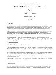
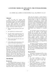
A MODEL TO SOLVE EN ROUTE AIR TRAFFIC FLOW MANAGEMENTThird, it could be easily adapted <strong>to</strong> cover cases with more than one alternative <strong>route</strong> a for flights i, i∈F a ,considering these <strong>route</strong>s as additional flights and adding the corresponding sums <strong>to</strong> the left side of theconstraints (3).4. PROPOSED SOLUTIONThe LP relaxation approach is used for solving the BIP <strong>model</strong> (1−4). LP relaxation of the BIP <strong>model</strong> is <strong>solve</strong>dusing a standard LP package. If the solution is integer, it is an optimal one and the value of the objectivefunction (1) repres<strong>en</strong>ts the minimum <strong>to</strong>tal delay cost. Otherwise, each flight i with value 1 for correspondingvariable x i,k is served with delay k. Th<strong>en</strong> all flights with non−integer values for some of the correspondingvariables are served by applying one of the heuristic approaches described in Tosic et. al. (1995).5. NUMERICAL EXAMPLEIn this section, results of one of the conducted experim<strong>en</strong>ts will be pres<strong>en</strong>ted in order <strong>to</strong> illustrate theapplication of the developed <strong>model</strong> and proposed method of solution. It is similar <strong>to</strong> the numerical exampleused in Tosic et. al. (1995) were we had N=4 ATC sec<strong>to</strong>rs (North=N, East=E, South=S, West=W) and T=8half−hour time periods with 162 flights in set F each int<strong>en</strong>ding <strong>to</strong> fly <strong>en</strong>−<strong>route</strong> through some of those foursec<strong>to</strong>rs. In this example we introduce two more ATC sec<strong>to</strong>rs, N' and E' (Figure 1) offering two alternativeroutings for the two most loaded <strong>air</strong> <strong>traffic</strong> <strong>flow</strong>s, namely NE <strong>flow</strong> with 45 flights and EN <strong>flow</strong> with 26flights.Those flights are "offered" the following alternative <strong>route</strong>s: for NE flights, the alternative <strong>route</strong> is N'E' and forEN flights the alternative <strong>route</strong> is E'N'. Remaining flights of other <strong>traffic</strong> <strong>flow</strong>s are not offered alternative<strong>route</strong>s. Therefore the initial <strong>to</strong>tal <strong>traffic</strong> load remains the same as in the example used in Tosic et. al. (1995),as well as sec<strong>to</strong>r capacities per period which were set equal <strong>to</strong> Q jt =18 flights (j=1,2,3,4, i.e. j=N,E,S,W andt=1,2,...,8). Sec<strong>to</strong>rs N' and E' have capacities Q 5t =Q 6t =9 (t=1,2,...,8) because of the load produced by flightsflying through those two sec<strong>to</strong>rs on their original <strong>route</strong> (flights not considered in this example), so those twocapacity values should be unders<strong>to</strong>od as remaining sec<strong>to</strong>r capacities.Alternative <strong>route</strong>s N'E' and E'N' are equal in l<strong>en</strong>gth and take 1/3 of a half−hour time period (10 minutes)longer <strong>to</strong> fly than their respective original <strong>route</strong>s NE and EN. It is assumed that all flights originally in NE andEN <strong>flow</strong>s will fly the same extra amount of time wh<strong>en</strong> flying on alternative <strong>route</strong>s for reasons of simplicity.For the same reason, we assume that the ratio of cost per unit time wh<strong>en</strong> the <strong>air</strong>craft is in the <strong>air</strong> and wh<strong>en</strong> it ison the ground equals 4 (Andrews 1993), and this value was used for all flights. We used the same coeffici<strong>en</strong>tsc i as in the previous example, Tosic et. al. (1995) where the function of <strong>air</strong>craft size giv<strong>en</strong> ranged from 0.1 for<strong>air</strong>craft up <strong>to</strong> 15 seats <strong>to</strong> 4.0 for <strong>air</strong>craft with 320 <strong>to</strong> 450 seats. We have therefore the following values forcoeffici<strong>en</strong>ts c i '(k) and c i " in objective function (1): c i '(k)=c i ⋅k and c i "=4⋅1/3⋅c i =4/3⋅c i . Maximum permittedground delay per flight i was set at k i * =4 half−hour time periods and was assumed equal for all flights. Th<strong>en</strong>,maximum permitted delay for flights i on alternative <strong>route</strong>s a was calculated as k a * =int(k i * − 1/3)=3 and wasalso assumed equal for all flights assigned <strong>to</strong> alternative <strong>route</strong>s.4
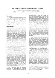
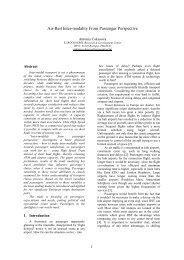
A MODEL TO SOLVE EN ROUTE AIR TRAFFIC FLOW MANAGEMENTFigure 1: Example <strong>flow</strong> patternsUsing the proposed method of solution, we obtained the following results: 148 flights were scheduled on timeflying their original <strong>route</strong>s, 5 flights had ground delays and were also assigned <strong>to</strong> their original <strong>route</strong>s with a<strong>to</strong>tal of 7 half−hour time periods of ground delay, while 9 flights were assigned <strong>to</strong> alternative <strong>route</strong>s withoutground delay.The results are shown in Figures 2 and 3, compared <strong>to</strong> the results of the case wh<strong>en</strong> only temporal solution wasallowed.5
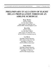
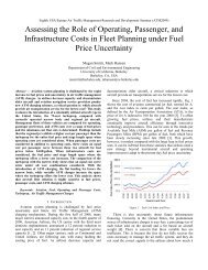
A MODEL TO SOLVE EN ROUTE AIR TRAFFIC FLOW MANAGEMENTFigure 2: Distribution of ground delay for flights assigned <strong>to</strong> original and alternative <strong>route</strong>sFigure 4 repres<strong>en</strong>ts the state of capacity loads through time periods after solving our example FMP (shadedfields in the table indicate that <strong>traffic</strong> load has reached the sec<strong>to</strong>r capacity per time period).This solution differs from the one obtained using only ground delays, as described in Tosic et. al. (1995)where we had 145 flights on schedule and 17 flights with differ<strong>en</strong>t l<strong>en</strong>gths of ground delay <strong>to</strong>taling 43half−hour time periods of delay.Figure 3: Per flight delay6
A MODEL TO SOLVE EN ROUTE AIR TRAFFIC FLOW MANAGEMENTGLO−CTPeriodSec<strong>to</strong>r 1 2 3 4 5 6 7 8 9N 10 18 18 18 18 18 18 18 < 9 + 8E 9 14 14 18 18 17 18 18 < 9 + 9S 11 17 14 10 16 13 11 12 < 9 + 0W 5 11 10 5 14 11 9 7 < 9 + 0GLO−ACTPeriodSec<strong>to</strong>r 1 2 3 4 5 6 7 8 9N 10 18 17 18 18 16 18 18 < 9 + 0E 9 14 13 17 18 17 18 17 < 9 + 1S 11 18 14 9 18 12 11 11 < 9 + 0W 5 12 9 6 14 10 9 7 < 9 + 0N’ 3 2 1 2 4E’ 2 2 1 4 5 1Figure 4: System load after solving the example problemThe value of objective function in a similar example described in Tosic et. al. (1995) was 31.6 which is muchhigher wh<strong>en</strong> compared with the value of 17.0 obtained with combined ground delay and alternative routing.6. DISCUSSION AND CONCLUSIONSThe <strong>model</strong> offers a spatial solution for FMP combined with a temporal one. G<strong>en</strong>erally speaking, this is a veryrealistic approach and should be available <strong>to</strong> the decision maker.It is obvious that the solution gained by offering alternative <strong>route</strong>s beside simple ground hold is quite differ<strong>en</strong>tfrom the above m<strong>en</strong>tioned solution obtained by Tosic et. al. (1995). Here both <strong>to</strong>tal cost and <strong>to</strong>tal grounddelay are less for flights on original <strong>route</strong>s. In this example, th<strong>en</strong> it can be concluded that, under abovedescribed assumptions, it is worth offering alternative <strong>route</strong>s for heavy load <strong>traffic</strong> <strong>flow</strong>s.REFERENCES1. V. Tosic and O. Babic, "Air Route Flow Managem<strong>en</strong>t − Problems and Research Efforts",Transportation Planning and Technology, Vol. 19, pp. 63−72 (1995).7
A MODEL TO SOLVE EN ROUTE AIR TRAFFIC FLOW MANAGEMENT2. V. Tosic, O. Babic, M. Cangalovic and Dj. Hohlacov, "Some Models and Algorithms for En RouteAir Traffic Flow Managem<strong>en</strong>t", Transportation Planning and Technology, Vol. 19, pp. 147−164(1995).3. John W. Andrews, "Impact of Weather Ev<strong>en</strong>t Uncertainty upon an Optimum Ground−HoldingStrategy", Air Traffic Control Quarterly, Vol. 1, No. 1, pp. 59−84 (1993).8